COST EVALUATION OF BUILDING
SPACE HEATING: DISTRICT HEATING
SYSTEM AND HEAT PUMPS
SAHIRA SULTAN
School of Business, Society and Engineering
Subject: Degree Project in Sustainable Energy Systems Level: Advanced
ECTS: 30 hp
Program: Master of Science in Energy Engineering Course code: ERA401
Supervisor: Maher Azaza Examiner: Anders Avelin Date: 10/12/2017
ABSTRACT
Climate change and energy efficiency has become a matter of concern in recent times; therefore, energy efficiency of buildings has drawn major attention. According to the European Commission, EU countries must improve energy efficiency of existing buildings by retrofitting and renovating the buildings. A case study of a renovated commercial building is considered in this degree project. A model of the building is developed in the IDA Indoor Climate and Energy (IDA ICE) software. The model is then augmented to include renovations in the building. Further, the model is simulated in IDA ICE before and after renovations to investigate the impact of renovations on energy consumption of the building for one year. The simulation results indicate peak demands of district heating that occur in the coldest days of the year. The peak demands of energy are expected to increase the district heating cost because they serve as a basis for new pricing model introduced by the energy providers. Hence, it is important from the customer point of view to reduce the peak loads for cost shavings. The project work also provides an insight into the alternative source of energy such as heat pumps to reduce the peak load demands of district heating.
Keywords: Energy efficiency, energy consumption, commercial buildings, IDA ICE, peak
SUMMARY
Climate change and energy efficiency has become a matter of concern in recent times; therefore, the concepts of energy efficiency and energy performance of buildings have drawn major attention. The buildings within European union (EU) hold a large share of its total energy consumption. According to Energy performance of buildings directive, EU countries must set minimum energy performance requirements for new buildings, for the major retrofitting and renovation of old and existing buildings. Moreover, EU countries have to draw up lists of national financial measures to improve the energy efficiency of the buildings. Building sector in Sweden is responsible to fulfill Minimum Energy Performance Requirement (MEPR), as per EU directives in Sweden (Boverket). For this purpose, new buildings are constructed according to the MEPR, while the old buildings are either renovated or retrofitted to meet the MEPR.
This work uses a case study of a renovated commercial building to investigate the energy consumption of the building before and after renovation. A building model is developed in simulation software IDA ICE and total energy consumption is calculated before and after renovation to study the impact of renovation on energy demand of the building. Renovation has reduced 41.225 MWh of total energy consumption of the building and hence saved district-heating costs.
The building model is simulated for one whole year and energy consumption behavior of the building is studied. It is found that there are some peak demands of district heating occurring in the coldest days of the year. The peak demands of energy are important to study from cost point of view because a prospective pricing model for district heating is based on peak demands of the building and is expected to increase the costs of district heating.
From customer point of view, it is necessary to reduce the peak demands of energy in order to keep the energy costs minimum. An alternative source of heat energy such as heat pump is investigated so that it can be used as a supplement to reduce the peak loads during peak demand duration. An air-to-air heat pump is modeled under certain weather conditions and satisfactory results for the performance of pump are collected. A variable air volume (VAV) system for handling the air is also investigated to study the energy consumption of the building.
Keywords: Energy efficiency, energy consumption, commercial buildings, IDA ICE, peak
TABLE OF CONTENTS
1 INTRODUCTION ... 1
1.1 Degree Project Goal... 1
1.2 Research Questions: ... 2
1.3 Delimitations ... 2
2 LITERATURE REVIEW ... 3
2.1 Energy Efficiency of Existing Buildings ... 3
2.1.1 Building Envelope ... 3
2.1.2 Water and Space Heating ... 3
2.1.3 Lighting and Appliances ... 3
2.2 Related Work ... 4
2.2.1 Energy Efficiency of Buildings ... 4
2.2.2 Cost Evaluation ... 4
2.2.3 Contribution to The Study ... 5
3 METHODOLOGY ... 6
3.1 Research Methodology ... 6
3.2 Technical Approach and Description of Building Model in IDA ICE ... 7
3.2.1 Building Description ... 7
3.2.2 IDA ICE Description ... 9
3.2.3 Building Envelope ... 9
3.2.4 Air Handling Units ... 12
3.2.5 Miscellaneous Parameters... 12
3.2.6 Model Description ... 13
3.2.7 Variable Air Volume (VAV) model... 15
3.3 Heat Pump Modeling ... 16
3.3.1 Selection Criteria ... 18
3.3.2 Assumptions ... 18
3.3.3 Equations ... 19
3.4 Pricing Model ... 19
3.4.2 Electricity ... 21
4 RESULTS ... 23
4.1 Old Building Model Results ... 23
4.1.1 Delivered Energy ... 23
4.1.2 Delivered Energy Overview ... 23
4.1.3 Monthly Purchased/Sold Energy ... 24
4.1.4 Operative and Mean Air Temperature in a Zone ... 25
4.1.5 Delivered Energy Simulations for one Year ... 25
4.1.6 District Heating Supply Behavior in February 2017 ... 26
4.1.7 District Heating Supply Behavior in a Week ... 27
4.2 Renovated Building Model Results ... 28
4.2.1 Delivered Energy ... 28
4.2.2 Delivered Energy Overview ... 28
4.2.3 Monthly Purchased/Sold Energy ... 29
4.2.4 Delivered Energy Simulations for a Year ... 30
4.2.5 District Heating Supply Behavior in February 2017 ... 30
4.2.6 District Heating Supply Behavior in a Week ... 31
4.3 Heat Pump Calculations ... 32
4.3.1 Peak Load Shaving ... 33
4.4 Variable Air Volume Results ... 34
4.4.1 Delivered Energy ... 34
4.4.2 Delivered Energy Overview ... 34
4.4.3 Monthly Purchased/Sold Energy ... 35
4.4.4 Delivered Energy Simulations for a Year ... 36
4.4.5 District Heating Supply Behavior in January 2017 ... 36
4.4.6 District Heating Supply Behavior in a Week ... 37
4.5 Pricing Models Analysis ... 38
4.5.1 Electricity ... 38
4.5.2 District Heating ... 38
5 DISCUSSION ... 39
5.2 Variable Air Volume (VAV) Model Results ... 40
5.3 Heat Pump Calculations and Results ... 40
5.4 Evaluation of the Pricing Models ... 41
6 CONCLUSIONS ... 42
7 PROPOSAL FOR FURTHER WORK ... 43
LIST OF FIGURES
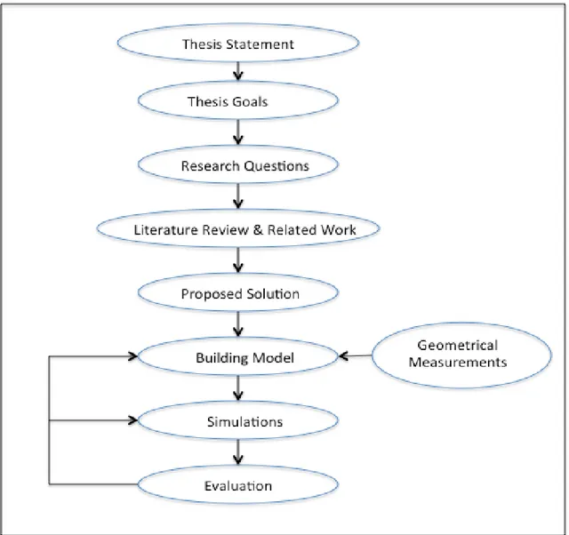
Figure 1: Research Methodology ... 6
Figure 2: Image of Ånghammargatan 5 (CASTELLUM) ... 7
Figure 3: Geometrical Representation of the Building (Self-drawn) ... 8
Figure 4: Side View of the Building (Self-drawn) ... 9
Figure 5: 2-Dimensional View of Zone Geometry in IDA ICE ...14
Figure 6: 3-Dimensional View of Building in IDA ICE ... 15
Figure 7: Schematic Diagram of Heat Pump (Self-drawn Image) ...16
Figure 8: logp-h diagram for refrigerant used in heat pump (sellf-drawn image) ... 17
Figure 9: New Pricing Model for District Heating by Mälarenergi (MälarEnergi) ... 21
Figure 10: Wholesale Electricity Prices in Sweden (Hirth) ... 22
Figure 11: Summary of Delivered Energy (Image from Energy Report given by IDA ICE) ... 23
Figure 12: Delivered Energy Overview (IDA ICE) ... 24
Figure 13: Graphical Representation of Purchased Energy on Monthly Basis ... 24
Figure 14: Graphical Representation of Air Temperature Within a Zone (IDA ICE) ... 25
Figure 15: Delivered Energy for Year 2017 (IDA ICE) ... 26
Figure 16: Delivered Energy Behavior in February 2017 (IDA ICE) ... 26
Figure 17: Delivered Energy Behavior during 1st Week of February (IDA ICE)... 27
Figure 18: Summary of Delivered Energy (IDA ICE) ... 28
Figure 19: Delivered Energy Overview of the Building (IDA ICE)... 29
Figure 20: Graphical Representation of Purchased Energy within Year 2017 (IDA ICE) ... 29
Figure 21: Energy Delivered by District Heating Throughout the Year 2017 (IDA ICE) ... 30
Figure 22: Delivered Energy Behavior in February 2017 (IDA ICE) ... 31
Figure 23: Delivered Energy Behavior during 1st Week of February 2017 (IDA ICE) ... 31
Figure 24: Peak Load Comparison of District Heating Demand With and Without Heat Pump ... 33
Figure 27: Graphical Representation of Monthly Purchased Energy (IDA ICE) ... 35
Figure 28: Delivered energy Simulations for year 2017... 36
Figure 29: District Heating Energy Behavior in January 2017 ... 37
Figure 30: District Heating Energy Behavior in Second week of January 2017 ... 37
LIST OF TABLES
Table 1: Summary of Building Envelope Systems and Materials ... 11
Table 2: Summary of Renovations done in Building Envelope Systems and Materials ... 12
Table 3: Summary of Miscellaneous Parameters used in the Building Model ... 12
Table 4: Height Adjustments for Building Model Calculations ... 13
Table 5: Summary of Fenestration Geometry used in Building Model ...14
Table 6: Heat Pump Calculations Results ... 32
ABBREVIATIONS
ABBREVIATION DESCRIPTION UNITS
∆ℎ𝑒𝑣𝑝 Enthalpy difference of Evaporator kJ/kg
∆ℎ𝑐𝑜𝑚𝑝 Enthalpy difference of Compressor kJ/kg
∆ℎ𝑐𝑜𝑛𝑑 Enthalpy difference of Condenser kJ/kg
𝑄̇𝑐𝑜𝑚𝑝 Power/Work of Compressor kW
𝑄̇𝑐𝑜𝑛𝑑 Power/Work of Condenser kW
𝑄̇𝑒𝑣𝑝 Power/Work of Evaporator kW
𝑚̇ Mass flow rate Kg/s
ℎ Enthalpy kJ/kg
𝐶𝑂𝑃 Co-efficient of Performance ----
MEPR Minimum Energy Performance Requirement ----
AHU Air handling units ----
CAV Constant air volume ----
HVAC Heating, ventilation and air-conditioning ----
VAV Variable air volume ----
DH District heating ----
ASHP Air source heating pump ----
1
INTRODUCTION
Heating of an enclosed area such as a room or building done with a heat source is known as space heating. Space heating is also termed as central heating when it comes within a large building. It is one of the most energy consuming services provided to the residential and commercial sector in a low temperature region. In Europe, most of the space heating for buildings is provided by a central heat distribution network system known as district heating system. The buildings within European union (EU) hold a large share of its total energy consumption. According to a report by the European Commission, energy consumed by the buildings amounts to 40% of the total energy consumption and 36% of the CO2 emissions in the EU. The report further mentions that currently, 35% of the EU buildings are 50 years old, which make them higher consumers of the energy. There are two main legislations in EU that govern the reduction of energy consumption in buildings: (1) 2010 Energy performance of buildings directive and (2) 2012 Energy efficiency directive (European Commission).
According to the 2010 Energy performance of buildings directive, EU countries must set minimum energy performance requirements for new buildings, for the major renovation of old buildings and for the replacement or retrofit of building elements (heating and cooling systems, roofs, walls, etc.). Moreover, EU countries have to draw up lists of national financial measures to improve the energy efficiency of buildings.
According to “Energy efficiency directive”, EU countries must make energy efficient renovations to at least 3% of buildings that are owned and occupied by central government and EU governments should only purchase buildings, which are highly energy efficient. Moreover, EU countries must draw-up long-term national building renovation strategies which can be included in their National Energy Efficiency Action Plans.
In Sweden, the residential and service domain consumes 40% of the total energy used in the country (Energy in Sweden 2015, 2015). This domain comprises of various consumers such as residential buildings, public administration infrastructures and commercial infrastructures including non-residential buildings and energy-consuming services such as water treatment and power production facilities.
Building sector in Sweden is responsible to fulfill Minimum Energy Performance Requirement (MEPR), as per EU directives in Sweden (Boverket). For this purpose, new buildings are constructed according to the MEPR, while the old buildings are either renovated or retrofitted to meet the MEPR.
1.1 Degree Project Goal
The main goal of this degree project is to investigate the efficacy of prospective price model of district heating system that provides space heating to a retrofitted building. For this purpose, we consider a use case of a commercial building owned by CASTELLUM, which is one of the largest real-estate companies in Sweden. The company provides commercial properties such as office spaces, warehouses and industrial buildings. The company is also responsible for reconstructing and renovating its properties. However, to maintain the sustainability, the
company focuses on the efficient use of energy and water services. It also aims at extending and reconstructing the properties according to high environmental standards. For this purpose, the company has renovated one of its buildings, “Ånghammargatan 3,4 and 5” to minimize the energy consumption of the building. The building is currently connected to district heating network. The renovation is done for the walls, ceilings, windows and land by inserting windows of better U-value and additional insulations, hence minimizing the energy costs. Current district heating pricing is season based, but new alternative pricing strategies are coming to the market soon that can affect the energy costs of the buildings owned by the company. In order to keep the energy costs minimum, it is required to investigate the high-energy peaks that can provide a basis for district heating prices calculations according to the expected pricing model of district heating. Moreover, an alternative source for the reduction of peak loads has to be investigated.
1.2 Research Questions:
The investigation conducted in this work aims at answering three Research Questions (RQs), which are formulated as follows.
RQ1: How does retrofitting affect energy consumption of the building and hence the energy costs according to the existing district heating prices?
RQ2: How does the prospective district heating pricing model affect the energy cost of the retrofitted building?
RQ3: Given the answer to RQ2, how do alternative sources of energy affect the cost of space heating for the retrofitted building?
1.3 Delimitations
The model of building developed to do main project work is limited to the building considered in this work. The model cannot be used for another building with different specifications. The performance of heat pump is evaluated for specific conditions. Electricity and district heating market analysis is limited to the area where the building is situated.
2
LITERATURE REVIEW
Literature review for the current work is divided in two sections. One is an overview of energy efficiency of existing buildings and other is related work section.
2.1 Energy Efficiency of Existing Buildings
Space heating also termed as central heating is provided to provide comfort to the occupants and users of a building. In a low temperature region such as Europe, district-heating network is the most common way of space heating delivered to the consumers. In Sweden, main consumers of space heating are residential and commercial sectors, which are responsible for about 40% of total energy use within the country. Therefore, improving the energy efficiency of residential and commercial buildings can lead towards a substantial reduction of energy use of country resulting in greenhouse gases emission reduction also.
Energy efficiency of buildings depends on various factors such as building design, building envelope, space heating and cooling, water heating, lighting and electrical appliances used in the building. New buildings offer more opportunities for application of efficient energy integration options while the old buildings can undergo renovation or retrofitting to achieve high-energy efficiency.
2.1.1 Building Envelope
Building envelope is an important factor responsible for the energy use of a building. It includes walls, insulation, foundation, basement slab, ceiling, roof and windows. An efficient building envelope is built when all its components work together to give higher energy efficiency of a building. Applying a good insulation or fitting the glass, doors and windows with a better U-value can improve the building envelope and hence the energy efficiency of existing buildings.
2.1.2 Water and Space Heating
Water and space heating of a building can be made energy efficient by improving the water fixtures, automated control, ventilation, and duct system. Higher energy efficiency of the building can be achieved by improving these utilities.
2.1.3 Lighting and Appliances
Efficient energy savings lighting system can be used to increase the energy efficiency of a building. The old appliances such as freezers, refrigerators, ovens or dishwashers can be replaced by energy-efficient alternatives.
2.2 Related Work
2.2.1 Energy Efficiency of Buildings
There is a large body of research done by the research community on energy consumption measures, reduction strategies and cost evaluation for residential and commercial buildings. For instance, (L. De Boeck, 2015) presented a literature review on the improvement of energy performance in residential buildings. E.H. Borgstein discussed a comprehensive review of the current methods that can be used to analyze, classify and evaluate the energy performance for non-domestic buildings (E.H. Borgstein, 2016).
Luc et al. investigated energy consumption and indoor climate of a newly built single-family house in Greenland. They observed 45 % reduction in the energy consumption used for space heating of the building, which is achieved by the introduction of heat recovery measures in the ventilation system (Katarzyna M. Luc, 2016). Thomsen et al. investigated the energy consumption of a residential building, located in Denmark, before and after a comprehensive retrofitting. They identified improvement in the thermal comfort and air quality of the building along with reduction in the energy consumption for space heating (Kirsten Engelund Thomsen, 2016).
Gourlis et al. conducted a case study of a historical industrial building to analyze building envelope refurbishment. They evaluated the improvement of energy efficiency by studying two retrofit scenarios and dynamic thermal simulations of the building model developed in Energy Plus simulation software (Georgios Gourlis, 2016).
Molin et al. evaluated the energy performance of a newly built residential area in Sweden. In their study, they found that the energy limits set by the forum for energy efficient buildings (FEBY) have been met by the improved design and heating control of the building (Andreas Molin, 2011).
Liu et al. evaluated energy consumption and indoor environment of a retrofitted multi-family building located in the city of Linköping, Sweden. They compared their results with a similar non-retrofitted building in the same area (Linn Liu, 2015).
2.2.2 Cost Evaluation
Mikulić et al. investigated the economic impact of energy saving retrofits used for residential and public buildings in Croatia and concluded that an individual investor finds the energy-efficient renovation investment costs are viable when the government supports the procedure (Davor Mikulić, 2016). Matic et al. calculated economic feasibility of energy refurbishment of a prefabricated house located in new Belgrade, Serbia (Dubravka Matic, 2015).
Friedman et al. analyzed cost benefit of energy retrofit of a residential building envelopes in Israel and concluded that insulating the roof or walls of a residential house are not economically feasible according to current electricity prices and building construction costs in Israel (Chanoch Friedman, 2014).
Stocker et al. investigated cost optimal renovation and energy performance of existing school buildings that are located in Alps and proposed optimum thickness of insulation and optimum U-value for windows (Emanuel Stocker, 2015).
Mangold et al. estimated the costs of renovations and energy retrofitting of multi-family dwellings for conducted energy retrofitting projects in Gothenburg, Sweden and proposed to
increase the pace of renovation but also introduced a risk of increasing societal inequality due to high rents of the renovated buildings (Mikael Mangold, 2016).
2.2.3 Contribution to The Study
In contrast to the above-mentioned works, this project work focuses on energy saving measurements of a commercial building, located in the city of Västerås, before and after renovations and retrofitting done on the building. Energy consumption behavior and pricing strategies affecting the energy costs of the building are studied in detail and results are presented.
This work also performs cost evaluation and energy savings comparison of the current district heating pricing model with the prospective district heating pricing strategy. In addition, alternative energy sources are investigated for the purpose of lowering energy price under the new district heating price model.
3
METHODOLOGY
Research methodology and Technical approach to do the project work is discussed here.
3.1 Research Methodology
The first step is to define the main project goal by studying the work statements given by the company and project coordinators. The main challenges and possible outcomes of this project work are identified and research questions are designed after defining the scope of this work. Literature review is done to search possible solutions for the task that leads towards building of a model for this specific case. Simulations are done and results are retrieved from the software used to build the model. The results are evaluated and presented to answer the RQ1. Using the results of the model identifies the answer of RQ2. The model needs be augmented with some additional sources to answer the RQ3.
3.2 Technical Approach and Description of Building Model in IDA ICE
3.2.1 Building Description
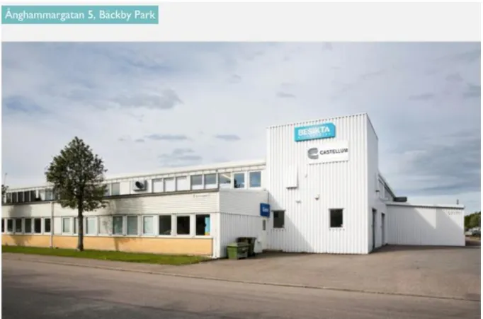
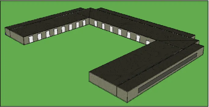
Ånghammargatan 3, 4 and 5 is a commercial building located at Bäckby Park, Västerås city and is owned by CASTELLUM. It is a U-shape building comprised of three houses namely E, F and G built in 1976. This building consists of warehouses, offices and workshops. It covers an approximate area of 4956 m2. To improve energy efficiency of the building, some
renovations are done recently for example windows having good U-value have been installed and the old insulations have been replaced with new and better ones. Actual building can be seen in Figure 2.
Figure 2: Image of Ånghammargatan 5 (Source: (CASTELLUM))
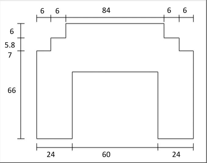
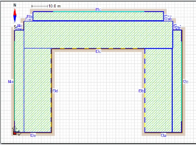
The building measurements and parameters are studied by the original blue prints regarding the construction of the building. A plenty of useful data and information is extracted by these blueprints provided by Västerås Stad. Building parameters of the building (length and width) are summarized in Figure 3 below.
Figure 3: Geometrical Representation of the Building (Self-drawn)
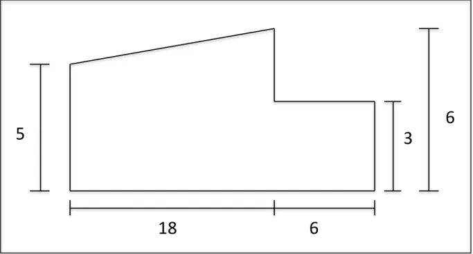
Height of the building is an important geometrical parameter of the building, because it is different for different parts of the building. Also height of building affects the energy needs of the building. Drawing the side view of the building shows the variations of the height of building. The side view of the building is shown in Figure 4 below.
84
6
6
6
6
60
24
24
6
5.8
7
66
Figure 4: Side View of the Building (Self-drawn)
3.2.2 IDA ICE Description
IDA Indoor climate and energy (ICE) is a dynamic simulation software that is used to study indoor climate of a building and calculate the energy consumption of the whole building. A building with specific geometry can be built in software that might reflect the real building geometry. The indoor space of building can be divided in a number of zones and climate and energy calculations can be done for individual zones or the entire building. The software requires several input parameters from the user. Some of these important parameters are weather and wind flow data for a specific location, power requirements of the building, energy requirements of the personnel, air handling units (AHU) inputs, controller settings, schedule settings and number of individuals using the building (EQUA, 2013). Geographic location is one of the important input parameters of the software because it is used to calculate proper solar radiation and other external climate factors that are required in the internal settings to translate different differential equations in order to calculate mathematical model of the building.
The software is able to calculate two mathematical models of the building. One is climate and the other one is energy model. Both models use the same input parameters of the building. However, in this study the focus is on energy model to investigate energy requirements of the building.
3.2.3 Building Envelope
An outer shell of elements that is used to maintain a heated or cooled environment within a solid structure is known as building envelope (Syed, 2012). Building envelope not only separates the indoor environment of a building from the effects of outer climate physically
5
3
6
but it also supports the load of the building and controls the flow of matter and energy in and out of the building.
Building envelope design is a very important part of the construction process of a building. It is comprised of following main components (National Institute of Building Sciences).
1) Below grade systems
Below grade systems provide an extended workspace for the building below grade level and it can be used as storages, offices, parking, HVAC/mechanical/electrical rooms or tunnels. Below grade systems have three main components; that are a foundation wall, slabs on grade and plaza decks. The system supports and controls the structural and environmental loadings (National Institute of Building Sciences).
2) Wall systems
The enclosure for a building is mainly built in the form of exterior walls system around the area, which provides a structural support for the building. The exterior wall systems not only separate the internal and external environments but they also provide a protected internal space and conditioned environment by controlling the flow of heat, air, moisture and bulk rain. Some common elements of wall systems are exterior cladding, air barrier system, insulating material and structural element.
3) Fenestration systems
Fenestration systems include glazing, windows, curtain walls and exterior doors. Main function of fenestration system is to allow daylight into the building with protection from the climate. Insulating Glass glazing made of glass is commonly used to improve energy efficiency and performance of commercial buildings.
4) Roofing systems
Roof is an important part of a building providing the isolation and protection of internal space and environment from the external climate impacts. Roof system consists of roof deck, air barrier, roof insulation and accessories. Steel or concrete roof decks are used for larger/higher buildings whereas plywood or oriented standard board (OSB) can be used for roof decks of smaller buildings.
The building “Ånghammargatan 3, 4 and 5“ considered for this work is studied and most of building envelope systems and materials used to construct the building are extracted from the blueprints provided by Västerås Stad. Some materials are however assumed due to unavailability of information.
Building envelope systems and materials used in the model for old building (before renovation) are summarized in table 1.
System Specifications Thickness (m) External Walls Gypsum 0.05 Light Insulation 0.3 Air 0.02 Chipboard 0.028 Internal Walls Gypsum 0.03 Light Insulation 0.045 Gypsum 0.03 Roof Gypsum 0.05 Cellplast 0.35 Light Insulation 0.2 Air 0.02 Chipboard 0.028 Internal Floors Chipboard 0.016 Light Insulation 0.04 Concrete 0.1 Light Insulation 0.1
Glazing 2 Pane Glazing, Clear, 4-12-4
Table 1: Summary of Building Envelope Systems and Materials
It is informed by the company that some renovations are done on the building such as insulations are replaced and windows are replaced with a low U-value glazing. However, much detail is not available. Therefore, renovated building model is developed mostly on assumptions. The idea is to replace glazing with low U-value as compared to the old building model and light insulation with heavy insulation, so that U-value of entire building can be minimized. All other parameters are kept same for the old building and renovated building models.
Summary of building envelope systems and material used for renovation of building are summarized in the table 2 below.
System Specifications Thickness (m)
External Walls
Gypsum 0.05
Heavy Insulation 0.3
Air 0.02
Chipboard 0.028
Glazing 3 Pane Glazing, Clear, 4-12-4-12-4
Table 2: Summary of Renovations done in Building Envelope Systems and Materials
3.2.4 Air Handling Units
Air handling unit is one of the main contributors of the energy consumption picture of any building. Type of air handling unit and input parameters of the system drastically change the amount of energy delivered to the building (YORK). Twenty to thirty years ago, commercial buildings in Sweden were installed with constant air volume (CAV) unit to maintain the heating, ventilation and conditioning of indoor environment (MARI-LIIS MARIPUU). Therefore, it is highly likely that “Ånghammargatan 3, 4 and 5“ are also installed with CAV unit.
Building model in IDA ICE, thus considers AHU to be installed with CAV unit. Supply and return air for CAV unit is kept at 1 L/(s.m2).
3.2.5 Miscellaneous Parameters
Building model in IDA ICE requires some parameters to be filled because these parameters affect the power and energy mapping of the building. These parameters are summarized below in table 3.
Parameters Specifications
Controller Set points Temperature 21 – 25 oC
Number of Occupants 100
Number of Equipment 65
Number of Lights 280
3.2.6 Model Description
Simulation software IDA ICE is used to simulate the model of building “Ånghammargatan 3, 4 and 5” in order to study energy requirements of the building during a year. Energy delivered to the building by district heating network is calculated for 12 months of the year.
3.2.6.1 Building Geometry
The geometry of the building is built in 3-dimensonal space provided by the software. Length and width of the building can be drawn in the model as it is shown in Figure no. 3. But height of the building is adjusted to get a flat roof of the building.
Height Adjustment
The model of the building is assumed to have a flat roof; therefore height adjustment of the building is necessary to be done to not affect the actual results too much. Actual volume of the building is calculated to be 24015.36 m3. To find an equivalent height for the model, hit
and trial method is used. Height of building is assumed and volume of building is calculated. Then relative error between the actual height and assumed height is calculated. The height giving the least relative error is taken to build the model. Assumed heights and relative error calculations are summarized in the table 4.
Assumed Height (m) Volume of Building (m) Relative Error (%)
5 24777.6 3.0763
4.9 24282.048 1.0982
4.85 24034.272 0.0786
4.8 23786.496 0.9529
4.5 222299.84 7.1434
Table 4: Height Adjustments for Building Model Calculations
Zone Geometry
Zone distribution is an important step of the model development in IDA ICE. The building is divided in six zones and each zone covers a part of the building. Zone distribution of the building can be seen in Figure 5.
Figure 5: 2-Dimensional View of Zone Geometry in IDA ICE (Self-Drawn)
Fenestration Geometry
Fenestration geometry of a building includes its windows, curtains, glazing and exterior doors. These important parts of the building are necessary to build in the model because length and height of a window affects the energy flow in and out of the building. Same is the case with exterior doors. However, some assumptions are made here. The number of windows for each zone is calculated and a big window of same parameters is put in the model. The geometrical parameters of windows and doors are summarized in the table below.
Zones 1 and 2 3
1st Floor 2nd Floor 1st Floor 2nd Floor
Windows Height (m) 1.1 1.1 1.1 1.1 Length (m) 0.9 0.9 0.9 0.9 No. 57 57 65 65 Total Height (m) 2.2 2.2 Total Length (m) 51.3 58.5 Doors Height (m) 4 Length (m) 2.8
IDA ICE provides three-dimensional (3D) view of the building where walls, roof and fenestration systems can be easily seen. 3D image of the building shows how the building under study looks like in Figure no. 6.
Figure 6: 3-Dimensional View of Building in IDA ICE (Self-Drawn)
3.2.7 Variable Air Volume (VAV) model
Heating, ventilation and air-conditioning (HVAC) system is designed and installed in a building to provide comfort to the occupants of the building. Comfort established in a space depends on combination of two parameters i.e. temperature and humidity. The comfort zone is the range of temperature and humidity conditions that must satisfy the people occupying the working space. Inside working environment needs outside fresh air to maintain healthy air for the occupants therefore, HVAC system conditions the supply air for acceptable humidity and temperature levels and also provide outside air for ventilation purposes. The combination of air supply and temperature parameters defines the types of HVAC system. These types are
• Constant Volume-Variable Temperature • Variable Volume-Constant Temperature • Variable Volume- Variable Temperature
Variable air volume (VAV) system differs from the constant air volume (CAV) system in a sense that it supplies a variable airflow at a constant temperature while CAV supplies a constant air volume to the building at variable temperatures. VAV systems are more energy efficient systems to maintain a comfortable temperature for an indoor environment as compared to CAV systems.
In Sweden, commercial buildings constructed in 80s and 90s were installed with constant air volume (CAV) unit to maintain the heating, ventilation and conditioning of indoor environment (MARI-LIIS MARIPUU). Therefore, the old building model and renovated building model were investigated by assuming CAV system installed in the building.
The building energy consumption pattern of district heating is investigated for VAV system also by using the option for the Air handling unit available in the software. The results are summarized in section 4.4.
3.3 Heat Pump Modeling
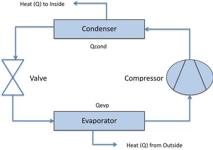
Heat pumps are energy efficient devices used for air-conditioning, refrigeration and space heating of both residential and commercial buildings (IEA-ETSAP, IRENA, 2013). They use a refrigerant to extract energy from a low-temperature heat source and deliver it to high temperature heat sink with the help of electricity. Refrigerant flows in a closed loop cycle that contains an evaporator, a compressor, a condenser and a pressure-reducing valve. An air-to-air heat pump is modeled to study the amount of heat energy delivered to the building during cold weather.
Figure 7: Schematic Diagram of Heat Pump (Self-drawn Image)
Condenser
Evaporator
Compressor
Valve
Heat (Q) to Inside
Heat (Q) from Outside
Qcond
Figure 7 shows a simple schematic diagram of a heat pump. The evaporator lies outside the building while the condenser inside the building. Refrigerant liquid flowing through the evaporator gets evaporated by the outside air and enters the suction side of the compressor. Compression of vapor increases the pressure and temperature of the vapor. The vapors then enter the condenser where condensation of vapors takes place by rejecting the heat energy to the inside of building. Allowing the condensate through the pressure-reducing valve then reduces its pressure. (IEA-ETSAP, IRENA, 2013)
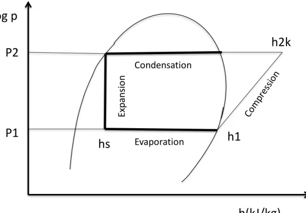
Logp-h diagram for the refrigerant is always a center of discussion when modeling a heat pump because heat pump performance greatly depends on the refrigerant properties. Figure 8 shows logp-h diagram for a heat pump where x-axis represents enthalpy of liquid in kJ/kg and y-axis represents log of pressure developed by the system.
Figure 8: logp-h diagram for refrigerant used in heat pump (sellf-drawn image)
Evaporation line shows an increase of enthalpy of liquid refrigerant at a constant pressure P1 from point hs to h1, when it flows through the evaporator. The evaporator in this case is
outside air that evaporates the liquid by adding energy into it. The liquid turns into vapor phase and the vapor enters the compression stage. A compressor increases the pressure of the vapor along with a slight increase in enthalpy of vapor where it reaches point h2k at a
pressure P2. The vapor then passes through a process of condensation in a condenser. The vapor gets condensed at a constant pressure P2 with a decrease in enthalpy from point h2k to hs. During the process of condensation, vapor rejects its energy to the heat sink, which in this
case is indoor environment of a building. The vapor then flows through the pressure-reduction valve where its pressure is reduced from point P2 to P1.
Log p
h(kJ/kg)
P2
P1
hs
h1
h2k
Evaporation
Condensation
Ex
pan
sio
n
3.3.1 Selection Criteria Condensation Temperature
Condensation temperature is an important factor of the refrigeration cycle. The refrigerant condensates at a temperature of 60oC that is helpful in creating a comfortable indoor
environment (Perko, 2011). The vapor entering the condenser rejects its heat to the indoor air, hence maintaining the air at a comfortable temperature.
Refrigerant
Refrigerant used in the heat pump is of great importance because its properties affect the operation and installation costs of the system. One important property of refrigerant is its condensation pressure at a given temperature. Some refrigerants have much higher pressure at a specific temperature as compared to others that may result in an inoperability of normal heat pumps components. Low pressure of refrigerant at a specific temperature requires an increase in its volume, hence increasing the investment costs. (De Kleijn Energy Consultants & Engineers)
In current work, a simple heat pump is considered, therefore, R600 n-butane is chosen as a refrigerant to simplify the requirements of heat pump components. Properties of R600 n-butane are used in the calculations carried out for the modeling purpose.
Condenser Capacity
Condenser capacity of a heat pump defines the amount of energy delivered to the high temperature heat sink. Heating efficiency of air source heating pumps (ASHP) significantly decreases below -3oC but efficient ASHPs can provide sufficient heating down to -17oC.
(Konrad, 2014)
J. Perko and V. Dugec have designed a heat pump for a building having an area of 180 m2 and
height of 2.8m and found that a heat pump of 11kW condenser capacity is enough to maintain a comfortable temperature within the internal environment. (Perko, 2011)
In this project work, a condenser capacity of 11 kW is selected and input power to the compressor is calculated. Coefficient of performance (COP) is calculated to evaluate the heating efficiency of the system under certain climate conditions.
3.3.2 Assumptions
To simplify the model and calculations, following assumptions are taken. • No pressure drop occurs in condenser.
• Condensation temperature remains constant at 60oC. • No sub cooling of liquid takes place.
• No enthalpy changes over the valve. • No superheating occurs in evaporator.
3.3.3 Equations
The equations used to model the heat pump system are summarized in this section.
∆ℎ𝑒𝑣𝑝 = ℎ1− ℎ𝑠 (1) ∆ℎ𝑐𝑜𝑚𝑝 = ℎ1𝑘− ℎ1 (2) ∆ℎ𝑐𝑜𝑛𝑑 = ℎ1𝑘− ℎ𝑠 (3) 𝑚̇ = 𝑄̇𝑐𝑜𝑛𝑑 ∆ℎ𝑐𝑜𝑛𝑑 ̇ (4) 𝑄̇𝑐𝑜𝑚𝑝 = 𝑚̇ ∗ ∆ℎ𝑐𝑜𝑚𝑝 (5) 𝑄̇𝑒𝑣𝑝= 𝑚̇ ∗ ∆ℎ𝑒𝑣𝑝 (6) 𝐶𝑂𝑃 = 𝑄̇𝑐𝑜𝑛𝑑 𝑄̇𝑐𝑜𝑚𝑝 (7)
Enthalpy (kJ/kg) of refrigerant R600 are extracted manually from the logp-h diagram in the software CoolPack. Works done in evaporator, compressor and condenser are calculated using equations 1, 2 and 3 in terms of kJ/kg. Heating capacity or condenser capacity is taken 11 kW in this case, so mass flow rate of refrigerant can be calculated by equation 4. Total work done by compressor and evaporator are calculated by equation 5 and 6 respectively. COP of compressor is the ratio of heating capacity to the electrical input to the compressor.
3.4 Pricing Model
The two public utilities i.e. space heating and electricity are delivered to the customers by energy generation companies on a cost paid by the customer. In Sweden, there are a number of power and heat generation production companies that offer a variety of pricing models to their customers in the country. These pricing models not only vary from company to company but also municipality to municipality. Therefore, price differences are very large within the country.
3.4.1 District Heating (DH)
In Sweden, space heating is mostly provided by district heating network, which covers more than 50% heat requirements of the country (Song, 2017). DH system is a centralized system of piping network used for the distribution of hot water to meet the energy demands of end-user. It is considered to be an efficient and cost-effective heating method that equally contributes to the mitigation of climate change.
District heating prices differ mostly geographically from one another. Several pricing models for DH are available given by a number of companies. The heat generation companies use combined heat and power plants (CHP) to provide DH to the consumers. The fuel mix used
in the CHP plants has become more diverse as low cost fuels such as biofuel, municipal waste and natural gas are used for heat generation. Therefore, the price of heat delivered is set accordingly. But when heat demand increases, the plants have to burn highly expensive fossil fuels or oils, which in result increases the cost of energy generation. Therefore, DH prices fluctuate according to the heat demand increase.
In district heating systems, the base load is covered with operating plants of low cost while the peak load is met by putting expensive plants into operation, thus affecting the profit of the company by increasing the production cost and maintenance cost of the plants. Another challenging factor for the production companies is decreasing demand of district heating due to the renovation and energy efficient measures taken to increase energy efficiency of buildings. Therefore, some companies have started to restructure their pricing models of DH to reduce their own risk level.
In this study, the building under consideration is located in the city of Västerås, Sweden; therefore, the pricing models affecting the heating prices of the building will be discussed here.
Pricing Model 2017
MälarEnergi is a local company providing heat and electricity to the city of Västerås, Sweden. The company is currently using a season price model for district heating. This model is based on different prices for different season of the year. There are three levels of the seasonal pricing model: 1) Summer, 2) Autumn/Spring and 3) Winter. The model reflects varied prices for these three levels. The price of DH is lowest in summer and highest in winter when the heat demand increases. (MälarEnergi)
The seasonal model offered by Mälarenergi consists of two components. One is variable price and the other is fixed price. Variable price component offers highest heating prices for the months January, February and December whereas lowest prices for the months of May to September for a year. Fixed price component offers fixed fee/subscription and connection cost/kW/year. (MälarEnergi)
Upcoming Model 2018
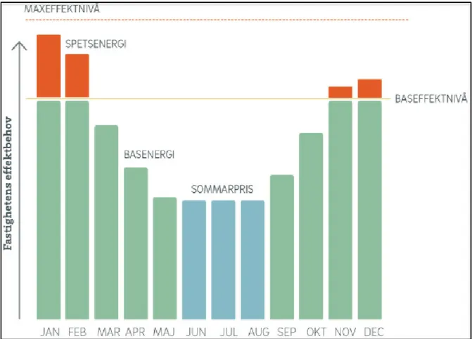
Mälarenergi is going to introduce a new pricing model for district heating energy in 2018, which is based on users real consumption data of energy. New prices will be effective from August 1, 2018. The main components of the model are base energy, tip energy and maximum power level. The heating price will be charged according to the spikes of energy consumption occur during maximum heat demand duration. (MälarEnergi)
Figure 9: New Pricing Model for District Heating by Mälarenergi (MälarEnergi)
The buildings “Ånghammargatan 3, 4 and 5” is a commercial building with high consumption of energy and produces high energy demand spikes during the coldest days of the year when heat demand goes vey high. These high peaks can be reduced by addition of some alternative source of energy so that district heating prices don’t shoot up in winters. One of these alternative sources of energy might be heat pump that can serve as an efficient source of energy to maintain the energy requirements of building in colder days. Their coefficient of performance (COP) remains stable usually between 3 and 5 from colder to warmer days, which means that a heat pump can deliver 3 to 5 kWh of heat for every kWh of electricity it consumes (Perko, 2011). Therefore, heat consumption pattern of the building can be actively managed during winters.
3.4.2 Electricity
Sweden produces electricity from several sources such as hydropower, biofuel, renewable technologies and fossil fuels. In 2014, the country has produced 555TWh of energy from all the available sources from which 143TWh is consumed by Industrial sector (Swedish Energy Agency, 2014). It means that industrial sector is major consumer of electricity. Electricity production has been stable for about last 10 years in the country despite an increase in the usage of electrical appliances (Swedish Energy Agency, 2014). The reason may be because of more energy efficient devices are coming to the market.
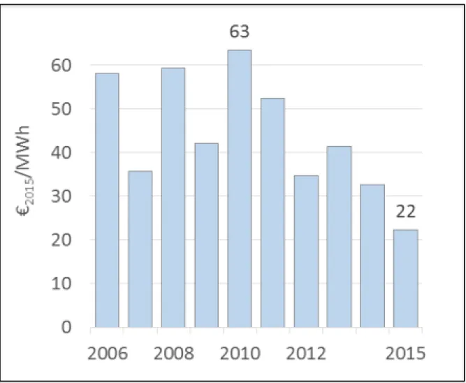
Wholesale electricity prices have been reduced to 65% in Sweden since 2010. Figure 10 shows electricity prices since 2006. (Hirth)
Figure 10: Wholesale Electricity Prices in Sweden (Hirth)
There are several factors that contributed to the electricity price drop which are decrease in energy demand, increase in power production of renewable technologies, decline in fossil fuel prices and increased supply from newly-commissioned coal-fired and natural gas-fired plants (Hirth). It means that the electricity prices in the country tend to remain same at least in near future.
Mälarenergi offers different contracts for electricity consumption to the consumers. Most of these contracts can be agreed up to even 5 years. It means that the consumer will not suffer price increase for a long term despite an increase in the electricity prices.
4
RESULTS
Two models for the building “Ånghammargatan 3, 4 and 5” are built in the simulation software “IDA ICE” and simulated to study energy consumption of the building. The results of simulations are presented in this section.
4.1 Old Building Model Results
A model of building is developed in software as it was first built in reality; therefore, the model is referred to be old building model. The parameters governing the model development are briefly described in section 3.2. The model is simulated as an energy model for duration from 1/1/2107 to 12/31/2017 and a brief energy report is extracted from the software. The results for delivered energy to the building are given below.
4.1.1 Delivered Energy
Delivered energy to the building is the total energy usage by District heating and cooling, lighting, HVAC and equipment installed in the building throughout the year. Total energy delivered for 12 months of the year 2017 is summarized in the table below (taken from energy report).
Figure 11: Summary of Delivered Energy (Image from Energy Report given by IDA ICE)
4.1.2 Delivered Energy Overview
Delivered energy overview can be studied in Figure no. 12 where total purchased energy for all the facilities and the peak demand for energy for these facilities are summarized.
Figure 12: Delivered Energy Overview (IDA ICE)
4.1.3 Monthly Purchased/Sold Energy
Figure no. 13 shows a graphical representation of purchased energy on a monthly basis for the whole year. The red bars represent the district heating delivered to the building for 12 months of year 2017. It can be seen that the district heating is higher for colder months and lowest for the hot season of the year.
4.1.4 Operative and Mean Air Temperature in a Zone
Operative air temperature and mean air temperature for a zone are summarized and presented by IDA ICE for duration of year 2017 as shown in the figure below.
Figure 14: Graphical Representation of Air Temperature Within a Zone (IDA ICE)
Mean air temperature is measured as an average temperature of a well-mixed room at a uniform rate. A simple thermometer can read the temperature for a well-mixed dry room. Operative temperature is measured at occupant’s location, therefore; it refers to the temperature experienced by the occupant in a room. Mean air temperature is lower than operative air temperature because it is recorded at a location having well mixed air while the operative temperature is mean of air temperature and solar radiation. It means that strong solar radiations can cause high peaks of temperature.
4.1.5 Delivered Energy Simulations for one Year
Figure 15 shows delivered energy behavior throughout the year 2017. The energy behavior shows an increased energy demand in the months of January, February, November and December. Whereas, delivered energy is very low in warmer seasons of the year.
Figure 15: Delivered Energy for Year 2017 (IDA ICE)
4.1.6 District Heating Supply Behavior in February 2017
Figure 16 shows the district heating demand during the month of February 2017. The simulation of model can be done for any desired duration. The energy demand seems to be the highest in February for the old building model as shown in Figure no. 11 also. Therefore, energy behavior for February is focused here.
4.1.7 District Heating Supply Behavior in a Week
As the highest energy demand occurs in the month of February, so energy behavior can be briefly investigated on a weekly basis. Energy simulations are summarized for 1st week of
February as shown in the figure below.
4.2 Renovated Building Model Results
The building “Ånghammargatan 3, 4 and 5” had gone through renovation of walls and windows in order to improve energy efficiency of the building and to minimize the leakages through the openings. Much detail is not available on the renovation process of the building; therefore, the model for renovated building is developed in such a way that overall U-value of building must be lower than the old building model so that reduction of energy demand due to renovations can be studied briefly.
The results from the renovated building model are presented in this section.
4.2.1 Delivered Energy
Energy delivered to the building is found by simulating the renovated building model as an energy model for duration of one year starting from 1/1/2017 to 12/31/2017. The energy delivered per month can be obtained from the energy report summarized by IDA ICE as shown in Figure no. 18.
Figure 18: Summary of Delivered Energy (IDA ICE)
Energy supplied for all the facilities such as lighting, equipment, HVAC and district heating and cooling for 12 months of the year are presented in the table form. It is worth noting that total district heating is lower as compared to the old building model. Hence, the renovation of the building plays an important role in the reduction of energy consumption of the building.
4.2.2 Delivered Energy Overview
Delivered energy overview can be found in Figure no. 19 where total purchased energy for all the facilities is summarized along with peak demand of energy for these facilities.
Figure 19: Delivered Energy Overview of the Building (IDA ICE)
4.2.3 Monthly Purchased/Sold Energy
A graphical representation of purchased energy on a monthly basis for the whole year can be established by running the simulations of the model. The red bars represent the district heating delivered to the building on a monthly basis.
4.2.4 Delivered Energy Simulations for a Year
Energy delivered to the building by all means and specifically by district heating is simulated over a year and summarized as graphical representation as shown in the figure below. The graph shows the higher energy demands in the months from November to February and lower demands for the hot duration of the year.
Figure 21: Energy Delivered by District Heating Throughout the Year 2017 (IDA ICE)
4.2.5 District Heating Supply Behavior in February 2017
Peak load of district heating demand occurs in the month of February, therefore district heating supply behavior is extracted for this month. The behavior is shown in Figure no. 22 where daily district heating demand is illustrated.
Figure 22: Delivered Energy Behavior in February 2017 (IDA ICE)
4.2.6 District Heating Supply Behavior in a Week
District heating demand can be closely studied by viewing the demand behavior on a daily basis for a week. Energy behavior for first week of February 2017 is shown in Figure 23, where the demand can be closely investigated.
4.3 Heat Pump Calculations
Air source heat pump (ASHP) can be a good source of energy because of easy installation and low investment and maintenance costs. An air source heat pump with a heating capacity of 11kW is modeled in this study. The heat pump can be used as a supplement source in the month of February in order to avoid peak load demand of district heating. Section 4.2.5 shows that peak load demand occurs in the month of February; therefore the calculations of heat pump are done by taking the climate conditions of February into consideration. February is one of the colder months of a year when temperature drops below 0oC in
Västerås.
To simplify the calculations, outdoor temperature is taken to be -5oC. The enthalpy (kJ/kg) of
refrigerant at point h1 is taken at -5oC and h2k is taken at 60oC. The calculations for work
done by evaporator, compressor and condenser are done in an excel file. The results for the heat pump calculations are summarized in the table below.
Parameter Value Units
ℎ1 575 kJ/kg ℎ2𝑘 690 kJ/kg ℎ𝑠 346.6 kJ/kg ∆ℎ𝑒𝑣𝑝 228.4 kJ/kg ∆ℎ𝑐𝑜𝑚𝑝 115 kJ/kg ∆ℎ𝑐𝑜𝑛𝑑 343.4 kJ/kg 𝑄̇𝑐𝑜𝑛𝑑 11 kW 𝑚̇ 0.0320 Kg/s 𝑄̇𝑐𝑜𝑚𝑝 3.6837 kW 𝑄̇𝑒𝑣𝑝 7.3162 kW 𝐶𝑂𝑃 2.986 ----
Table 6: Heat Pump Calculations Results
It is worth noting that COP of compressor is 2.986 for the heat pump system chosen at outdoor temperature of -5oC. ASHPs can efficiently work until outdoor temperature reaches
0oC and their coefficient of performance (COP) remains stable between 3 – 3.5. With a
decreasing temperature, COP also decreases but the reduction of performance becomes significant below -3oC. (Konrad, 2014)
Significant advancement is being done to improve performance of air source heat pumps and the technology is still improving. Some modern ASHP models can maintain their COP above 1 even at very low temperatures such as -25oC.
In current case, the COP is calculated to be below 3 at an outdoor temperature of -5oC, which
means that ASHP can have a significant contribution to achieve a comfortable indoor temperature.
4.3.1 Peak Load Shaving
As the heat pump is considered to be a supplement source to avoid the peak load of district heating during the month of February, a picture of peak load shaving is presented here. The district heating demand for the February on hourly basis is exported to the excel file and the demand reduction due to addition of heat pump capacity on hourly basis is calculated. Reduction of hourly energy consumption of renovated building is taken into consideration because of the fact that the building is already renovated. Two behaviors of district heating demand with and without heat pump can be seen in Figure no. 24 below.
Figure 24: Peak Load Comparison of District Heating Demand With and Without Heat Pump (Self-Drawn)
IDA ICE calculates the peak demand of district heating to be 161.02 kW for renovated building as shown in Figure no. 19. Due to addition of energy delivered by heat pump, peak load is reduced to 150.03 kW. 0 20 40 60 80 100 120 140 160 180 1 16 31 46 61 76 91 10 6 12 1 13 6 15 1 16 6 18 1 19 6 21 1 22 6 24 1 25 6 27 1 28 6
D
is
tri
ct
H
ae
ting
D
em
and
(kW
)
Hours
District Heating
Energy (kW)
Delivered energy
reduction with
heat pump
4.4 Variable Air Volume Results
The variable air volume model for the building is simulated in order to investigate the district heating energy demand of the building when a more efficient HVAC system works for the building. The results for the model having VAV type of air handling unit are summarized here.
4.4.1 Delivered Energy
Delivered energy report consists of district heating and cooling energies and energies used by lighting, HVAC and equipment installed in the building. The values measured for these parameters for whole year are presented in the tabular form. Total energy delivered for 12 months of the year 2017 is summarized in the table below (taken from energy report).
Figure 25: Summary of Delivered Energy (IDA ICE)
4.4.2 Delivered Energy Overview
Delivered energy overview for VAV model can be found in Figure no. 26 where total purchased energy for all the facilities is summarized along with peak demand of energy for these facilities.
Figure 26: Delivered Energy Overview of VAV Model (IDA ICE)
4.4.3 Monthly Purchased/Sold Energy
A graphical representation of purchased/sold energy on a monthly basis for the whole year can be established by running the simulations of the model. The red bars represent the district heating delivered to the building on a monthly basis.
4.4.4 Delivered Energy Simulations for a Year
Energy delivered to the building by district heating and district cooling is simulated over a year and summarized as graphical representation as shown in Figure no. 28 below. The graph shows the higher energy demands in the months from November to February and lower demands for the hot duration of the year.
Figure 28: Delivered energy Simulations for year 2017 (IDA ICE)
4.4.5 District Heating Supply Behavior in January 2017
The simulations of VAV model of the building show that peak load of district heating demand occurs in the month of January; therefore district heating supply behavior is extracted for this month. The behavior is shown in Figure no. 29 where daily district heating demand is illustrated.
Figure 29: District Heating Energy Behavior in January 2017 (IDA ICE)
4.4.6 District Heating Supply Behavior in a Week
District heating demand can be closely studied by viewing the demand behavior on a daily basis for a week. Energy behavior for second week of January 2017 is shown in Figure 30, where the demand can be closely investigated.
4.5 Pricing Models Analysis
Section 3.4 discusses the pricing model for electricity and district heating offered by the heat and power provider company working in Västerås that is known as Mälarenergi. Pricing trends for both sectors have also been discussed in the section in detail. The analysis for electricity and district heating pricing is discussed below.
4.5.1 Electricity
In the view of electricity market pricing trend, it can be clearly seen that there is minimum chance for an increment in the electricity prices in near future. The electricity prices are going down and if they don’t, more chances are that the prices remain stable. Moreover, the consumer can sign a contract for same prices up till 5 years, so the consumer is less likely going to suffer the increased prices.
4.5.2 District Heating
District heating pricing sector tends to be more volatile and major variations in the prices for DH might be expected in future. As mentioned earlier, Mälarenergi is going to introduce new pricing model for district heating based on the hourly consumption data of the user. It is highly likely to expect a significant increase in district heating costs suffered by the consumer during colder months of the year. Therefore, an alternative energy source to actively manage the hourly consumption pattern is strongly recommended.
5
DISCUSSION
This chapter includes a detailed discussion of building model, simulations, heat pump model calculations and pricing models. The chapter is divided into different sections as stated below.
5.1 Old and Renovated Building Models
A model of building “Ånghammargatan 3, 4 and 5” is developed in IDA ICE to study the energy needs of the building and model is simulated for a year to investigate the energy requirements behavior during twelve months of the year. The energy requirements from district heating (DH) are a matter of focus here because variations of energy requirements of the building greatly depends on district heating that is found to be high in colder months and lower in hot seasons of the year.
The base load of district heating for the colder months is comparatively constant but there are some peak demands of DH that occur during these months. The peak demands of DH are very important when studying energy requirements behavior of the building because they are going to affect the overall cost of district heating.
The old model of the building under study is developed with some actual information and some assumptions that are required to build the model. An effort is made to reflect the true picture of building envelope and thus the energy consumption requirements of the building. The model of building is built in IDA ICE as it was constructed in original and then some renovations are included to get a comparatively good U-value for the whole building. Energy model is simulated for both cases and the results are obtained. The results show that by renovating the building, energy requirements of the building get lowered; especially district heating demand of the building is reduced due to renovations.
The difference between total district heating demand for old building and renovated building models is calculated to be 41.225 MWh. The peak demand for heating is also reduced from 174,9 W to 161,2 W, i.e. 7.83% reduction in the peak demand of heating is achieved by the renovations. It means introduction of good renovation measures for a building can reduce the cost of district heating. This cost reduction will be more visible when new pricing model based on the peak demand will become operational.
The building is divided in six zones to simplify the development of model in the simulation software IDA ICE. Some assumptions are taken regarding the building geometry, building envelope materials and their specifications for the old building as well as the renovated building models. The HVAC system of the building is also assumed to be constant air volume (CAV) system. These assumptions might have affected the results of energy consumption of the building. A more realistic model of the building can give a more realistic picture of energy and cost savings due to the renovations done on the building.