Semi-Automated Formalization and
Verification of Automotive Requirements
using Simulink Design Verifier
ROHIT AGRAWAL
Master of Science Thesis Stockholm, Sweden September 15th 2015
Semi-Automated Formalization and
Verification of Automotive
Requirements using Simulink Design
Verifier
Rohit Agrawal
Master of Science Thesis MMK 2015:71 MES 012 KTH Industrial Engineering and Management
Machine Design SE-100 44 STOCKHOLM
Examensarbete MMK 2015:71 MES 012
Semi-Automated Formalization and Verification of Automotive Requirements using Simulink Design
Verifier Rohit Agrawal Godkänt 2015-09-15 Examinator De-Jiu Chen Handledare
Jonas Westman (Industrial) Lei Feng (Academic)
Uppdragsgivare
Scania KontaktpersonJonas Westman
Sammanfattning
Komplexiteten för de inbyggda system som utnyttjas inom fordonsindustrin är alltjämt ökande då behovet av alltmer avancerade lösningar kräver fler funktioner. Detta har vart till stor fördel vid införandet av Model Based Design i arbetsflödet för mjukvaruutvecklingen vilket gett medel för att hantera komplexitet vid olika faser i utvecklingen. Simulation based testing är vidsträckt använt inom fordonsindustrin för att identifiera designfel i modellerna, dock har formal verification i motsats till Simulation based testing en nedärvd fördel att kunna granska hela designen systematiskt och matematiskt bevisa att systemet uppfyller kraven.
De största hindren för att kunna utnyttja formal verification till fullo inom fordonsindustrin idag är brist på kunskap inom formella metoder samt systemkrav i naturlig textform. Specification
Patterns i begränsad grammatisk engelska har visat vissa lovande resultat inom kravspecifikation
genom att undvika den stora mångfalden i språkstrukturen i det naturliga språket. Simulink Design
Verifier (SLDV) är ett verifikationsverktyg integrerat i MATLAB/Simulink som minskar behovet
av en separat formell modell samt begränsningarna i Simulink’s kapacitet att modellera krav. Detta examensarbete undersöker olika utmaningar angående formal verification med Simulink
Design Verifier och Specification Patterns för möjligheten att göra processen semi-automatiserad. Fuel Level Display System, en fallstudie vid Scania är specifikt framtagen som ett reellt industriellt
exempel för att undersöka möjligheten att utnyttja Simulink Design Verifier för modell krav, dess effektivitet som verifikationsverktyg, användningsmöjligheter för Specification Patterns samt bristerna för kraven i naturlig text.
Undersökningen rekommenderar att formal verification ska genomföras av system-ingenjörer/utvecklare genom Specification Patterns och SLDV, förutsatt att komplext beteende är specificerad inom en proposition/icke-bokstavlig form av Pattern. Detta komplexa beteende kan modelleras med hjälp av Simulink och SLDV block. Verifikation av krav är möjligt genom modellstrukturen i SLDV. De begränsningar som tillkommer genom användning av SLDV för att modellera vissa aspekter av kraven kan åtgärdas genom lämpliga förändringar i systemmodellen, detta utförs av systemutvecklare.
Master of Science Thesis MMK 2015:71 MES 012
Semi-Automated Formalization and Verification of Automotive Requirements using Simulink Design Verifier
Rohit Agrawal Approved 2015-09-15 Examiner De-Jiu Chen Supervisor
Jonas Westman (Industrial) Lei Feng (Academic)
Commissioner
Scania Contact personJonas Westman
Abstract
The complexity of embedded software in the automotive domain is ever-increasing due to increase in the no. of features aimed at providing more advanced solutions. This has greatly favored the incorporation of Model Based Design workflow in the software development lifecycle to handle complexities in different development phases. Simulation based testing is widely used in automotive domain to identify design errors in models. However, formal verification as opposed to simulation based testing has an inherent advantage of traversing the entire design space systematically and proving mathematically that the system satisfies the requirements. Lack of knowledge in formal methods and system requirements in their present form in natural text, form the biggest hindrances in making formal verification a reality in the automotive domain. Specification Patterns through their constrained English grammar have shown some promise in requirements specification by avoiding the diverse language structure of the natural language. Simulink Design Verifier (SLDV), a verification tool integrated with MATLAB/Simulink alleviates the need of a separate formal model and leverages on Simulink’s capability to model requirements.
This thesis investigates various challenges with regard to formal verification with Simulink Design Verifier and Specification Patterns with possibilities of semi-automating the process. Fuel Level Display System, a case study from Scania is specifically dealt with as a real industry example, to investigate the expressivity of Simulink Design Verifier for modelling requirements, its efficiency as a verification tool, usability of Specification Patterns and insufficiencies of requirements in natural text.
The investigation recommends formal verification to be carried out by system engineers/developers with help of Specification Patterns and SLDV, provided that complex behavior is specified within a proposition/non-literal term of Pattern. This complex behavior can be modelled with Simulink and SLDV blocks. The modelling framework of patterns in SLDV can be used to verify the requirements. The limitations posed by SLDV in modelling some aspects of requirements can be dealt with by making suitable changes to system model by system developers.
FOREWORD
This master thesis is the final year project of the Master’s program, Embedded Systems at KTH Sweden and constitutes 30 credits. It was conducted at Scania in the RESA department and is part of the VeriSpec (Structured Specification and Automated Verification for Automotive Functional Safety) research project. VeriSpec runs jointly in collaboration between Scania, Volvo and MDH. First of all, I would like to express my deepest sense of gratitude to my industrial supervisor Jonas Westman for instilling critical thinking and logical reasoning in me and guiding me throughout the project.I would also like to thank my second industrial supervisor Guillermo Rodriguez, not only for giving me this thesis opportunity but also helping me with technical writing. Lei Feng, my academic supervisor for helping me give shape to this thesis from an academic standpoint. Anton Einarson for help with administrative matters.
Special thanks to my family, friends and all the personnel at the RESA department.
Rohit Agrawal Stockholm, October 2015
NOMENCLATURE
Abbreviations
BMC Bounded Model Checking
SLDV Simulink Design Verifier
FLDS Fuel Level Display System
COO Coordinator
SESAMM Scania Electrical System Architecture made for Modularization and
Maintenance
IEEE Institute of Electrical and Electronics Engineers
ISO International Organization for Standardization
IEC International Electrotechnical Commission
LTL Linear temporal logic
CTL Computation Tree Logic
QRE Quantified Regular Expression
GIL Graphical Interval Logic
MTL Metric Temporal Logic
TCTL Timed Computational Tree Logic
RTGIL Real-time Graphical Interval Logic
XOR Exclusive or
EMS Engine Management System
ICL Instrument Cluster
CAN Controller Area Network
RTDB Real Time Data Base
TABLE OF CONTENTS
FOREWORD
5
NOMENCLATURE
7
TABLE OF CONTENTS
8
1
LIST OF FIGURES
10
2
LIST OF TABLES
11
3
INTRODUCTION
12
3.1
Background
12
3.2
Problem Statement
13
3.3
Goals
14
3.4
Method and Approach
14
4
LITERATURE REVIEW
15
4.1
Requirements on a system model
15
4.2
Specification pattern system
18
4.2.1
Scope
19
4.2.2
Requirement Behavior
19
4.3
Simulink design verifier
22
4.3.1
Formalizing requirements in SLDV
23
4.3.2
Creation of verification Model
25
4.3.3
Verification of the system
26
5
IMPLEMENTATION
28
5.1
Case Study: Fuel Level Display System
28
5.1.1
Simulink System Model
30
5.2
Transformation of requirements to Simulink Objects
33
5.2.1
Assumptions
35
5.2.2
Resolving Compatibility
38
5.2.3
Verification subsystem
39
5.3
Transformation of Requirements to Patterns
47
5.4.1
Discussion on Modelling Framework
50
5.4.2
Modelling Framework: Alternative 1
52
5.4.3
Modelling Framework: Alternative 2
53
5.4.4
Implementation of Scope Subsystem:
54
5.4.5
Implementation of Pattern behavior
56
6
ANALYSIS/ RESULTS
57
6.1
Requirements
58
6.2
Simulink Design Verifier
57
6.3
Specification Patterns
58
6.3.1
Consolidated results of Patterning
59
6.3.2
Simulation results of Patterns
60
6.4
Comparison between two approaches of Requirements formalization
67
7
DISCUSSION AND CONCLUSIONS
69
8
RECOMMENDATIONS AND FUTURE WORK
71
9
REFERENCES
72
1 LIST OF FIGURES
Figure 1: Model based Design Workflow [4] ... 12
Figure 2: Simulation based Testing vs Formal Verification [9] ... 13
Figure 3: System Model and Sample Requirements ... 16
Figure 4: Pattern Scopes ... 19
Figure 5: Qualitative Patterns [14] ... 20
Figure 6: Structured English Grammar of Patterns ... 22
Figure 7: Formal Verification with Simulink Design Verifier ... 23
Figure 8: Proof Blocks ... 23
Figure 9: Implies Block ... 24
Figure 10: Illustration of SLDV Assumption, Proof and Implies ... 24
Figure 11: Temporal Blocks of SLDV ... 25
Figure 12: Instrumenting System Model directly ... 25
Figure 13: Illustration of Verification Subsystem ... 26
Figure 14: Compatibility Check with SLDV ... 26
Figure 15: FLDS System Architecture ... 28
Figure 16: Sequence of Operation in COO ... 29
Figure 17: System Model in Simulink ... 30
Figure 18: Input Subsystem ... 31
Figure 19: Evaluate parking Brake ... 32
Figure 20: Algorithm subsystem ... 32
Figure 21: Fuel Level Estimation Algorithm ... 33
Figure 22: Requirement as contract ... 34
Figure 23: Verification Environment ... 34
Figure 24: Assumtions on Signal Values, Verifiation Variables and Environment variables ... 36
Figure 25: Assumptions subsystem on Parameter Values ... 37
Figure 26: Assumptions subsystem on Signal Status ... 37
Figure 27: Assumptions subsystem on Parameter Status ... 38
Figure 28: Compatibility Issue with Original Block ... 38
Figure 29: Compatibility replaced block ... 39
Figure 30: AER201_5 Initial verification Model ... 39
Figure 31: Counter Example for AER201_5 Initial verification Model ... 40
Figure 32: System Implementation for Kalman Gain Selection ... 40
Figure 33: AER201_5 Updated Verification Model Subsystem ... 41
Figure 34: AER201_5 Updated verification Model Implementation ... 41
Figure 35: Equations Governing Requirement AER201_6 ... 42
Figure 36: AER201_6 verification Model Subsystem ... 42
Figure 37: AER201_6 verification Model Implementation ... 43
Figure 38: AER201_7 verification Model ... 44
Figure 39: AER201_8 verification Subsystem ... 45
Figure 40: AER201_8 verification Subsystem Implementation ... 45
Figure 41: State Diagram Delay Illustration ... 45
Figure 42: Overall Requirement verification ... 46
Figure 43: Simulink Representation of Logical Connectives ... 51
Figure 44: Modelling Framework Alternative 1 ... 52
Figure 45: Issue with first Alternative... 53
Figure 46: Modelling Framework Alternative 2 ... 53
Figure 47: SLDV Result when scope is never entered... 54
Figure 48: Scope subsystem ... 54
Figure 49: Global scope ... 55
Figure 51: Before R ... 55
Figure 52: QuntilR ... 55
Figure 53: Implementation of Pattern Behaviour ... 56
Figure 65: Comparison on Patterning Results with Prior Case Study ... 59
Figure 66: Pattern Frequency ... 60
Figure 67: Simulation of After Q Scope ... 61
Figure 68: Simulation of Before R Scope ... 62
Figure 69: Simulation of QuntilR Scope ... 63
Figure 70: Bounded Invariance Property Failed Simulation ... 64
Figure 71: Bounded Invariance Property Satisfied Simulation ... 64
Figure 72: Bounded Response Property Failed Simulation ... 65
Figure 73: Bounded Response Property Satisfied Simulation ... 65
Figure 74: Bounded Recurrence Property Failed Simulation ... 66
Figure 75: Bounded Recurrence Property Satisfied Simulation ... 66
Figure 76: Comparison between formalization Approaches ... 67
Figure 77: Thesis Project Conclusion ... 70
Figure 78: SESAMM Specifier ... 71
2 LIST OF TABLES
Table 1: Types of Requirements ... 17Table 2: Guidelines for Good Requirements ... 18
Table 3: System Configuration Parameters ... 29
Table 4: Consolidated Results from SLDV verification ... 47
Table 5: Consolidated Results of Patterning ... 59
3 INTRODUCTION
3.1 Background
Model Based design is now increasingly being used throughout the development process in areas like control systems, communication systems and signal processing domains [1]. Executable specifications of system models help us in refining algorithms by identifying design trade-offs early without dealing with actual hardware [2] [3]. MATLAB and Simulink from The Mathworks1 have emerged as de facto standard for this purpose. This has also increased the importance of effective verification of the models at a preliminary level to avoid costly design flaws later in the development cycle after code generation. For an overall success of a design, it is crucial that it meets all the requirements [2]. These requirements can describe qualitatively the tasks to be performed by the system, performance characteristics quantitatively, operational conditions of the system etc. One such performance requirement on the power window example from [2] is specified as, “The window has to start moving within 200 [ms] after the command is issued.” Within the model based design workflow, these requirements can be verified with the help of testing or formal verification at model level or code level shown in Figure 1 [4].
Figure 1: Model based Design Workflow [4]
The motivation behind the incorporation of formal verification is threefold, Firstly, ISO26262 is the new standard for functional safety in automotive vehicles. It is though not mandatory for the heavy vehicle industry but Scania is investigating methods for its adoption [5]. ISO26262 encourages the use formal verification to verify software architecture design. It also recommends that formal or semi-formal notations are used in software architecture design and software unit design [6]. Secondly, formal verification is more reliable as it proves mathematically if the system model satisfies the requirements [7]. Thirdly, it also gives great insight into system behavior while also ensuring system safety by considering all possible execution paths and taking care of those corner cases which might sometimes be omitted by only simulation based testing [8] [9]. Therefore, the aim of this master thesis is to explore methods to incorporate automated or semi-automated formal verification methods into model based design workflow of Scania.
In Scania, model verification has been mostly confined to simulation based testing up till now which does not always ensure all potential system behaviors. The use of formal verification techniques including automated specification and verification, is under investigation by Scania currently under the VeriSpec project [5]. This master thesis is part of the VeriSpec Project.
The fundamental difference between simulation based testing and formal verification is depicted in Figure 2 [9].
Figure 2: Simulation based Testing vs Formal Verification [9]
3.2 Problem Statement
The two basic requirements for any model checker are formal requirements and formal model. It is recommended in [5] that the system engineers/developers (who developed the system) perform verification but they are not trained in formal methods and this creates the biggest hurdle in the incorporation of formal verification in development workflow. The model checking tools generally need a separate formal model of the system. However in case of Simulink Design Verifier (SLDV) which is a verification or testing tool with MATLAB/Simulink, the system model acts as the formal model. This is the biggest motivation behind using SLDV as the verification tool. But the usability of SLDV for modelling and verifying requirements needs investigation. Moreover, the requirements are still specified in natural language at Scania and are faced with inconsistencies, redundancies etc. [5]. Natural Language has a diverse language structure which may lead to requirements being interpreted differently by different readers. Therefore, the usage of Specification Patterns [10] is under investigation in Scania for requirements specification to prevent ambiguities of natural text. The prior study done at Scania on Specification Patterns showed that at times these patterns are unable to capture the exact semantics of the requirements and hidden engineer’s intent. The patterns can be too difficult to understand as well. This thesis investigates about specification patterns, SLDV and general challenges with regard to formal verification with the help of following research questions:
What are the challenges faced in verification of requirements in natural text for Scania's Example?
How usable are Specification Patterns in capturing requirements semantics and engineer's intent?
How usable is Simulink Design Verifier as a tool in modelling different aspects of requirements and verifying them?
Is automated formal verification of Simulink Models realizable at Scania within the development tool chain?
3.3 Goals
The transformation of requirements to SLDV’s verification objectives is dealt with, in this master’s thesis with different approaches (with and without Patterns) aiming to look for possibilities of automation. SLDV’s expressivity for modelling requirements while capturing their semantics precisely and its efficiency as a verification tool are also discussed.
The two approaches towards formalizing requirements that the master’s thesis deals with: o Transforming requirements (for Scania’s case study) to Simulink/SLDV blocks
following the notion of contracts and commenting SLDV as a tool for modelling and verification based on the challenges faced.
o Creating a Modelling Framework of requirements to SLDV verification objectives with Patterns while making sure that the Patterns capture the exact semantics of requirements
Comparison of the two approaches with discussion and recommendation
Critical Discussion on requirements for the case study based on the challenges faced and comparison with standards
Explore possibilities of seamless integration of the above techniques in the development workflow at Scania
3.4 Method and Approach
The research methods in this thesis project are a combination of Qualitative and Quantitative methods, though leaning more towards qualitative aspects. They are applied both exhaustively and in combination to investigate on different tools, to illustrate improvements made by the thesis project and they also guide the approach for solving the problems and accomplishing the goals. The requirements for the case study at Scania for Fuel Level Display System are compared to the guidelines for good quality requirements and are critically viewed for ambiguities and insufficiencies. This guided the first step in the project to understand the system in order to understand the requirements with subsequent verification on Simulink Design Verifier. This helped to give a good critical view about requirements.
SLDV is commented upon qualitatively based on the challenges faced during modelling and verification of requirements.
With regard to Specification Patterns, prior patterning done on the same system was deeply studied and was again critically viewed for its results and shortcomings. The comparison of Patterning carried out in this thesis project with that of the prior study is shown quantitatively to emphasize on significant improvement. The modelling frameworks of patterns to SLDV are judged on qualitative categories after discussion with the pattern experts and system experts. Their simulation results are used to validate the modelling since the case study alone is insufficient to validate all the patterns.
4 LITERATURE REVIEW
4.1 Theory of model checking with SLDV
Model checking has greatly evolved over time. The initial implementations of Model checking tools made use of explicit representations of state transition graphs which limited their industrial application due to an exponential growth of states thereby leading to the state explosion problem. Later, these tools used symbolic model checking through Binary Decision Diagrams (BDDs) holding characteristic function of a set of states rather than individual states. However, these were also limited in use for designs with components smaller than a certain size. These developments paved way to a more recent model checking technique called the Bounded Model Checking (BMC) [11] which also forms the basis of the Prover plugin engine used by Simulink Design Verifier as the refutation technique.
BMC can be applied for verifying both safety and liveness properties involving mainly two steps. Firstly, converting the sequential behavior specified in the requirement over a finite interval to a propositional formula. Secondly, using the satisfiability procedure of the SAT solver to find an assignment that proves or disapproves the propositional formula with more emphasis on finding counterexamples that disapprove the correctness [11]. In principle, the underlying state transition system tries to realize a finite length of ‘k’ transitions to reach the desired state necessary for the Boolean formula’s satisfiability. If it does not possible, the length is increased to a larger value of ‘k’ and the search is continued. BMC has been successfully applied in SAT tools like PROVER, SATO and GRASP with faster traversal of the state space without dealing with exponential growth of states in comparison to BDD which usually requires much more memory. BMC with SAT is also found to be faster than BDDs at finding shallow errors and giving shorter counter examples. However, BDDs are better at proving absence of errors [12]. With k-induction also incorporated along with BMC, inductive completeness is achieved with the rule that if a property ‘x’ is satisfied or remains invariant in every state of each execution of length ‘k’, the successor states in future executions will also satisfy ‘x’ [13].
Simulink Design Verifer makes use of the following tools:
Prover plugin: for model checking, provided by Prover Technology
Polyspace: for static code analysis, provided by MathWorks
This thesis work evaluates only the model checking feature of SLDV provided by the Prover Technology which is a combination of Bounded Model Checking (BMC) and induction based on K-induction rule for satisfaction of the proof objectives using a SAT solver [14]. Prover plug-in models the properties as propositional logic formulas to identify whether the formulas are tautology i.e. they evaluate to true for all appropriate assignments by application of proof procedures [15].
The functionality offered by Prover plug-in in Simulink Design Verifier mainly concerns verifying design against requirements. These requirements are statements of behaviors that are either desired or undesired by the system. For a Simulink system model, the requirements are modelled in SLDV through one or more Proof objectives that define the relation between input and output of the system model with logical connectives (AND, OR, IMPLIES etc.), or comparisons (<, >, >= etc.) or MATLAB functions or Stateflow charts. Additionally, there are proof assumptions that help to constraint the input signals as specified by the requirement to cater to the problem of state explosion. SLDV provides model support for fixed-point and floating-point models. SLDV generates explicit states for all its possible values with respect to the constraints enforced by Proof assumptions. SLDV does not represent real-time symbolically but rather generates explicit states for all possible values based on the sampling time of the Simulink model.
4.2 Requirements on a system model
The system engineers specify requirements that shall be satisfied by a system model. In the absence of knowledge of formal methods, the system engineers generally write requirements in natural language. A requirement in natural text may look like:
When ParkingBrakeApplied has status “Error”, replacement value “Not Set” shall be used.
These informal requirements are needed to be translated as formal properties understandable to the model checker, in this case SLDV. Every functional/safety requirement has a verification objective associated with it which needs to hold for the requirement to be satisfied by the model. This verification objective is defined for a behavior of an output signal/interface or an internal signal of a system model with/without some constraints on the input signals.
The various possibilities have been illustrated in Figure 3 with the help of an abstract System and some sample requirements. Sample Req1 and Sample Req3 are on output signal and internal signal respectively, without any constraints on the inputs whereas Sample Req2 and Sample Req4 have some constraints on input signals.
Figure 3: System Model and Sample Requirements
The behavior to be verified in a requirement can be a simple one as defined in Sample Req1 (greater than 5) or a complex combination of several propositions involving even temporal properties. The same is the case with constraints over input signals.
The most widely known requirements document standard is IEEE/ANSI 830-1998 (IEEE, 1998) [16]. This was later replaced by ISO/IEC/IEEE 29148:2011. As per ISO/IEC/IEEE 29148:2011 [17], System requirements can be defined as,
“System requirements are all of the requirements at the system level that describe the functions which the system as a whole should fulfill to satisfy the stakeholder needs and requirements, and is expressed in an appropriate combination of textual statements, views, and non-functional requirements; the latter expressing the levels of safety, security, reliability, etc., that will be necessary.”
They play the following roles in system engineering [17]:
Form the basis of system architecture and design activities.
Form the basis of system integration and verification activities.
Act as reference for validation and stakeholder acceptance.
Provide a means of communication between the various technical staff that interact throughout the project.
System requirements can be broadly classified into the following categories as per [17] shown in Table 1.
Table 1: Types of Requirements
Functional Requirements
Describe qualitatively the system functions or tasks to be performed in operation.
Performance Requirements
Define quantitatively the extent, or how well, and under what conditions a function or task is to be performed (e.g. rates, velocities). These are quantitative requirements of system performance and are verifiable individually.
Usability Requirements
Define the quality of system use (e.g. measurable effectiveness, efficiency, and satisfaction criteria).
Interface Requirements
Define how the system is required to interact or to exchange material, energy, or information with external systems (external interface), or how system elements within the system, including human elements, interact with each other (internal interface).
Operational Requirements
Define the operational conditions or properties that are required for the system to operate or exist.
Modes and/or States
Requirements
Define the various operational modes of the system in use and events conducting to transitions of modes.
Adaptability Requirements
Define potential extension, growth, or scalability during the life of the system.
Physical Constraints
Define constraints on weight, volume, and dimension applicable to the system elements that compose the system.
Design Constraints
Define the limits on the options that are available to a designer of a solution by imposing immovable boundaries and limits.
Environmental Conditions
Define the environmental conditions to be encountered by the system in its different operational modes.
Logistical Requirements
Define the logistical conditions needed by the continuous utilization of the system.
Policies and Regulations
Define relevant and applicable organizational policies or regulatory requirements that could affect the operation or performance of the system.
Cost and Schedule Constraints
Define, for example, the cost of a single exemplar of the system, the expected delivery date of the first exemplar, etc.
Taking into account the role of system requirements above, there are certain guidelines mentioned that characterize a good requirement in Table 2.
Table 2: Guidelines for Good Requirements Characteristic Description
Necessary The requirement defines an essential capability, characteristic, constant, and/or quality factor. If it is removed or deleted, a deficiency will exist which cannot be fulfilled by other capabilities of the product or process.
Implementation Independent
The requirement, while addressing what is necessary and sufficient in the system, avoids placing unnecessary constraints on the architectural design. The objective is to be implementation-independent. The requirement states what is required, not how the requirement should be met.
Unambiguous The requirement is stated in such a way so that it can be interpreted in only one way. The requirement is stated simply and is easy to understand. Complete The stated requirement needs no further amplification because it is
measurable and sufficiently describes the capability and characteristics to meet the identified business, mission, and stakeholder needs.
Singular The requirement statement includes only one requirement with no use of conjunctions.
Achievable The requirement must be technically achievable within constraints and requires advances in technology within acceptable risk.
Verifiable The requirement has the means to prove that the system satisfies the specified requirement. Verifiability is enhanced when the requirement is measurable.
Conforming In many instances, there are applicable government, industry, and product standards, specifications, and interfaces with which compliance is required. The requirement may also need to conform to an organizational template for its sentence structure.
These guidelines are adhered to for a critical discussion on the requirements of the fuel level display system by commenting on their quality.
4.3 Specification pattern system
A specification pattern describes a commonly occurring requirement on a finite state system model in common formalisms like LTL, CTL and also Qualified Regular Expressions (QRE)/Constrained English Grammar [18]. It captures the essential behavior specified in the requirement and also has a scope within which the behavior shall necessarily hold [19]. The ease of understanding patterns by non-experts and their utility in formal specification of requirements lies in the fact that they are represented in both Constrained English Grammar and common formalisms. Moreover, their use is advocated to restrict the engineers from using diverse language structure of free text which leads to inconsistency and ambiguity. All the patterns specified by Dwyer et al. are available in the online repository [20] with their respective mapping to common formalisms like LTL, CTL, QRE, GIL etc. The following sections 4.3.1 and 4.3.2, describe the essential components to be taken into consideration while specifying a requirement through patterns. The notion of state/event denoted by P, Q, R, S etc. throughout the description of patterns implicitly stands for events or combination of events in event-based formalisms and state formulas in state-based formalisms [21].
4.3.1 Scope
In most cases, the scope is defined by a starting and/or ending state or event and is thus, only a portion of the entire execution lifetime of a system. The only exception to the above statement is the scope “Global” which stands valid throughout the system execution lifetime irrespective of occurrence of any state/event. [21] Illustrates different scopes with respect to the total extent of system execution. This has been described in various prior works done on the conception of Specification Patterns [19][21][22][23] and also their reassessment for formalizing requirements [10][24].
Figure 4: Pattern Scopes
There are five kinds of scopes [19]:
Global:
The scope stands valid/true for entire system execution
Before Q:
The scope stands valid for the part of execution up to the first occurrence of a given state/event
After Q:
The scope stands valid for the part of execution after the first occurrence of a given state/event and remains valid thereafter for rest of the system execution
Between Q and R:
The scope stands valid in any part of the execution from one given state/event to another given state/event with a necessary implication on the other state/event (denoted by R here) to hold after the first state/event (denoted by Q here)
After Q until R:
The scope is valid like “Between Q and R” and the validity continues for the rest of the execution even if the second state/event does not occur.
4.3.2 Requirement Behavior
This section illustrates different behaviors/properties exhibited by a requirement that are captured by a pattern.
4.3.2.1 Qualitative Patterns
The preliminary work done on patterns by Dwyer et. al. in [19][21] described only the qualitative aspects of requirements without catering to timing information and were thus called qualitative specification patterns by Konrad et. al in [22]. They were divided into three major groups in [19][21]: occurrence patterns, order patterns and compound patterns, also illustrated in Figure 5 below.
Figure 5: Qualitative Patterns [19]
Occurrence Patterns:
o Absence: A given state/event does not occur within a scope. o Existence: A given state/event must occur anytime within a scope.
o Bounded Existence: A given state/event must occur at most k times within a scope.
o Universality: A given state/event occurs throughout the scope.
Order Patterns:
o Precedence: A state/event P must always be preceded by a state/event Q within a scope.
o Response: A state/event P must always be followed by a state/event Q anytime within a scope.
Compound Patterns:
o Chain Precedence: A sequence of states/events P1, . . . , Pn must always be preceded
by a sequence of states/events Q1 , . . . , Qm.
o Chain Response: A sequence of states/events P1, . . . , Pn must always be followed
by a sequence of states/events Q1 , . . . , Qm.
o Boolean Combinations: These patterns outline how Boolean combinations of scopes and properties can be applied in different cases.
4.3.2.2 Real-time Specification Patterns:
Embedded systems are used in a variety of critical systems performing a no. of time-dependent functionalities. Therefore the verification of embedded system model shall involve rigorous verification of time compliance whenever specified in the requirements. Dwyer et al.’s patterns [19] due to their qualitative nature, cannot be used to specify real-time properties over system models. Konrad et al. complemented the existing repository of Dwyer’s patterns [20] with real-time specification patterns to capture the temporal aspects of requirements in [22]. Though, the notion of scope is applicable to real-time specification patterns in the same way as that of qualitative patterns. The real time specification requirements are further been divided into three categories duration, periodic, and real-time order:
Duration:
o Minimum Duration Pattern: Describes the minimum amount of time a state formula has to hold once it becomes true.
o Maximum Duration Pattern: Captures that a state formula always holds for less than a specified amount of time.
Periodic:
o Bounded Recurrence Pattern: Denotes the amount of time in which a state formula has to hold at least once.
Real-time order:
o Bounded Response Pattern: Restricts the maximum amount of time that passes after a state formula holds until another state formula becomes true. o Bounded Invariance Pattern: Specifies the minimum amount of time a state
formula must hold once another state formula is satisfied.
Real-time specification patterns are also mapped to real-time temporal logics like MTL, TCTL and RTGIL.
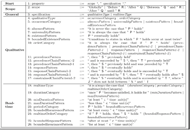
The Structured English Grammar representation of the qualitative and real-time patterns depicted in Figure 6 is developed by Konrad et al. [22].
“In the grammar, literal terminals are delimited by quotation marks (“ ”), non-literal terminals are given in a san serif font, and non-terminals are given in italics.” [22]
The biggest hindrance that has eluded the use of formal verification in automotive industry is the lack of knowledge in formal methods. The specification of requirements to patterns and thereby to common formalisms even by non-experts in formal methods solves the problem theoretically. An example of a requirement that specifies a proposition (P) to hold during the entire system execution can be represented by a Universality pattern with a global scope in the following manner: Constrained English Grammar: Globally, it is always the case that ‘P’ holds.
LTL: Globally, []P
The Constrained English Grammar restricts the engineer to make use of only specific English words which can be mapped into common formalisms unlike free text.
Figure 6: Structured English Grammar of Patterns
The Patterns were reassessed by many researchers with case studies done on industrial examples from the automotive domain [10] [24]. They discuss the applicability of the pattern system to express requirements written in natural language and comment about the expressivity and frequency of each pattern [10]. The work done by Filipovikj et al. in [10] was particularly relevant to this thesis as it was carried out on Scania’s example of Luel Level Display System. The implementation in this thesis report also compares its findings with [10].
The qualitative and real-time patterns were supplemented recently by Marco et al. in [23] by probabilistic patterns to express the probabilities of events. The probabilistic patterns need more reassessment for applicability in the automotive domain in the future. However, this thesis makes use of only qualitative and real-time specification proposed in [22]. For the following reasons. Firstly, no requirement in the Fuel Level Display System at Scania exhibited probabilistic events. Secondly, the preliminary process of automated formalization of requirements was explored with help of a simpler Pattern System.
4.4 Simulink Design Verifier
This section will elucidate some details of Simulink Design Verifier (SLDV) relevant for this thesis work. SLDV is a toolbox from MATLAB and Simulink. which uses formal methods to detect design errors like dead logic, integer overflow, division by zero and violations of design properties, assertions and functional and safety requirements [25]. Prover Plug-In® from Prover Technology is the underlying analysis engine behind SLDV which is based on Gunnar Stålmarck’s proof procedure for propositional logic [26]. In particular, SLDV employs Bounded Model Checking and K-induction features of Prover [27].
One of the key features of SLDV is verification of Design against Requirements. This feature is used throughout this thesis for formal verification of requirements. formal verification of a system model against requirements, with any model checker needs: i) formal model of the system and ii) formal requirement, as illustrated in Figure 7 [9]. In case of Simulink, the system model itself acts as the formal model for SLDV. This greatly strengthens the case of SLDV to be used as the model
checker for Simulink Models against other model checkers which need a formal model for verifying a system which is really difficult to make in the absence of knowledge of formal methods to system engineers.
Figure 7: Formal Verification with Simulink Design Verifier
4.4.1 Formalizing requirements in SLDV
SLDV allows usage of Simulink, MATLAB functions, Stateflow and SDLV library blocks for specifying the behavior to be verified. For specification of verification objectives and signal constraints, SLDV provides two blocks from its library [28] shown in Figure 8:
Figure 8: Proof Blocks • Proof Objective
Defines values of a signal to prove • Proof Assumption
Constrains the values of a signal during a proof
In addition to these blocks, SLDV also provides MATLAB and Stateflow functions for property proving in Simulink models and State flow chart.
Proof Functions:
• sldv.prove — Specifies a proof objective • sldv.assume — Specifies a proof assumption
Another block from the SLDV library that needs attention is the “Implies” block which is used widely for modelling basic requirements. Its functionality is analogous to the standard logical connective material implication shown in Figure 9 [29].
Figure 9: Implies Block
An illustration of the proof objective, proof assumption and implies block can be understood from Figure 10
Figure 10: Illustration of SLDV Assumption, Proof and Implies
In addition to the primitive blocks above for specifying basic properties, SLDV also offers temporal blocks for capturing the timing aspects in requirements. These can be used to accomplish the following behavior, if used individually illustrated in Figure 11:
Synchronize/delay the output with the Input
Extend a true signal for an infinite or finite duration
Test the presence of a true input within the true duration of another signal More complex behavior can be achieved with usage of temporal blocks in combination.
Figure 11: Temporal Blocks of SLDV
4.4.2 Creation of verification Model
The specification of the above proof blocks can be done on the system model in the following ways depending upon the complexity of the system model and requirements:
• Instrumenting the system model directly with Proof Assumptions and Proof Blocks for simple model and properties
Example [29]: The objective is to prove that the output from the XOR block always is true when one of the inputs are constrained to be false. Here the system itself is instrumented with Assumptions and Proofs in Figure 12:
Figure 12: Instrumenting System Model directly
For larger model
If the system has system-level properties that affect the behavior of the model. It is better to verify the properties without changing the model. The
verification of the properties now takes place in a separate model ‘verification model’ that contains a Model block to reference the original system model and also defines the properties on the design model interface using the same inputs and outputs or even internal signals. This approach is illustrated in Figure 13 [29] and followed during the implementation phase.
Figure 13: Illustration of Verification Subsystem
For a large model, properties of a subsystem in the model can be proved to review the analyses in smaller, manageable reports.
4.4.3 Verification of the system
SLDV can only analyze models that use a fixed-step discrete solver so appropriate settings are to be done in Configuration Parameters dialog box before starting the verification process. Moreover, all Simulink blocks are not compatible with SLDV so SLDV first checks for the compatibility of the system before analyzing it for property verification. The compatibility check can also be performed by the user manually and if compatible, the dialog box in Figure 14 is shown.
Figure 14: Compatibility Check with SLDV
In case the system model is incompatible with SLDV, the respective incompatible blocks in system model shall be made compatible with SLDV. Otherwise, SLDV performs Automatic Stubbing
wherein SLDV still analyzes the model by considering only interfaces of unsupported blocks and not their actual behavior so the block is allowed to take any value. This may lead to incomplete results.
The requirements can be verified in the property proving mode of SLDV by choosing appropriate option from the menu. SLDV shows the progress of verification and also displays that which objectives were proved, falsified or rendered incomplete results with different colors after verification:
Green: Objectives proved
Grey: Not part of verification
Red: Objectives disproved with counterexample and harness model for test cases which disprove the property. This helps in debugging the model to trace the error in the system model by simulating the model for the generated test cases.
Orange: Objectives disproved without counterexample or remained undecided. This may happen due to following reasons:
o A proof objective on a signal whose value the software cannot control, for example, a Constant block
o A proof objective that depends on nonlinear computation
o A proof objective that creates an arithmetic error, such as division by zero
o Automatic stubbing being enabled, and the analysis encountering an unsupported block whose operation it does not understand but that the analysis requires to generate the counterexample
o The analysis timing out
5 IMPLEMENTATION
5.1 Case Study: Fuel Level Display System
The case study used in thesis project is the Fuel Level Display System (FLDS) from Scania. This system was proposed by the project supervisors to be used because it is well documented and well understood by the engineers from the department within which this master’s thesis is carried out. This greatly facilitated the processes of system, requirements understanding and validation of results thereby making sure that more focus is laid on broader objectives than on trivialities. FLDS aims at calculating the fuel level of the tank continuously to make sure that the vehicle doesn’t run out of fuel. Fuel level is shown to the driver on the instrument cluster and a warning is generated if it falls below a pre-determined limit.
The functions of the FLDS can be divided into two broad categories:
1. Fuel level Estimation (AE201)
Estimates the current fuel level in the fuel tank. AE201 document (in appendix) details the requirements for this function.
2. Low fuel level warning (AE202)
Creates a warning if the fuel level. AE202 details the requirements for this function.
This master thesis project emphasizes only Fuel Level Estimation and its requirements specified in AE201. The FLDS comprises of different components and each component’s functionality is guided by the variant where the FLDS is equipped. The four major variants of the FLDS depending upon the vehicle and the fuel are:
1. Truck with fuel engine 2. Bus with fuel engine 3. Bus with gas engine 4. Truck with gas engine
These then have various sub-variants depending upon the parameter setting for sensor type, fuel tank type and fuel tank sizes. The different components of the FLDS are illustrated in Figure 15 comprising of different Electronic Control Unit (ECU) Systems namely Engine Management System (EMS), Coordinator (COO) and Instrument Cluster (ICL) [30]:
Figure 15: FLDS System Architecture
For simplicity, only one variant is taken into consideration i.e. truck with liquid fuel which is also the most relevant one in terms of implementation complexity. As earlier specified, within the above major variants there are also several sub-variants but again only one of them is considered based on the following parameters [31] to emphasize more on functional requirements than operational requirements Table 3:
Table 3: System Configuration Parameters
Input Parameters Truck with fuel engine Description
fuelLevelSensorParam 15 (Wema-general : short) controls the type of sensor and tank type
fuelTankSizeLeft 13 (450 liter volume: General) tank size on the left size fuelTankSizeRight 13 (450 liter volume: General) Tank size on the right side
fuelLevelTotalParam 10 (Total fuel level calculated by COO) controls if the total fuel estimation is done in CMS (truck) or received via CAN (bus)
In principle, with fuelLevelTotalParam = 10 the total fuel level is calculated by the COO. This is done with the help of a Kalman Filter which relies on the following as inputs:
Fuel level of the tank measured by a sensor
Current fuel consumption estimation provided by EMS
The estimated fuel volume is then sent to ICL over CAN. The ICL displays it to the driver with a warning if it goes below the pre-defined limit.
The sequence of fuel estimation in COO is depicted in Figure 16 while highlighting the part of its implementation done in Simulink called System Model.
Figure 16: Sequence of Operation in COO
A brief description of some variables used in the above figure enhances its understanding: parkingBrakeApplied: captures the application of parking brake to detect a refill of the fuel tank
fuelRate: fuel consumption estimation coming from EMS |FLS_|: Resistive sensor value [] for fuel level
|FLS_%|: Sensor value in percentage [%] for fuel level
|FLS_%_filt|: Sensor value in percent [%] for fuel level after low pass filter |FLS_vol|: Sensor value for fuel level in volume [m3]
Requirements on the above implementation are mentioned in AE201 document. Of which only the first fifteen requirements (AE201_1 to AE201_15) are applicable for the variant under consideration ‘truck with liquid fuel’. However AER201_1, AER201_2, AER201_3, AER201_10 and AER201_11 are defined for signals outside the Simulink system model so are not part of the verification process.
5.1.1 Simulink System Model
The system implementation of COO in Simulink caters to different variants and sub-variants. It makes use of a real time data base (RTDB) to interact with other components. The multiple instances of RTDB in the system model can be considered as user defined blocks in Simulink that store signals on both input and output sides. On the input side, RTDB mainly stores fuel consumption rate from EMS, fuel level sensor value and parking brake value. On the output side, RTDB stores fuel level calculated by COO and low fuel level indication which are eventually sent to ICL to indicate the fuel level and the low fuel level warning respectively. The RTDB is necessary for simulating the behavior of the COO for the specific values stored in it. However, in order to verify the system by covering the entire design space of inputs, the RTDB instantiations were replaced by generic input ports. More details about the verification process are made available in the next section after a brief explanation of the system model in Simulink shown in Figure 17.
Figure 17: System Model in Simulink
The entire system model is divided into four sub-systems mainly, Inputs, Algorithm, Route Output and Outputs. However, only the inputs and algorithm subsystems are relevant for the particular variant studied in this master thesis. A complete explanation of the above model is omitted due to space limitation and also to adhere to Scania’s privacy policy.
5.1.1.1 Inputs subsystem:
This subsystems models all the inputs including the ones mentioned above. The inputs to the system are signal values, parameters for configuration and their individual statuses:
Signal Values: fuelRate_Val_F32, fuelLevelSensor_Val_F32, oldFuelVolume_Val_F32, fuelLevelCatchSensor_Val_F32, pBrakeAppliedHigh_Val_B and fuelLevelTot_Val_F32
Signal Status: fuelRate_SS_U08, fuelLevelSensor_SS_U08, oldFuelVolume_SS_U08, fuelLevelCatchSensor_SS_U08, pBrakeAppliedHigh_SS_U08, fuelLevelTot_SS_U08
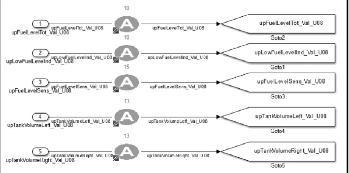
Parameter Values: upFuelLevelTot_Val_U08, upLowFuelLevelInd_Val_U08,
upFuelLevelSens_Val_U08, upTankVolumeLeft_Val_U08,
upTankVolumeRight_Val_U08
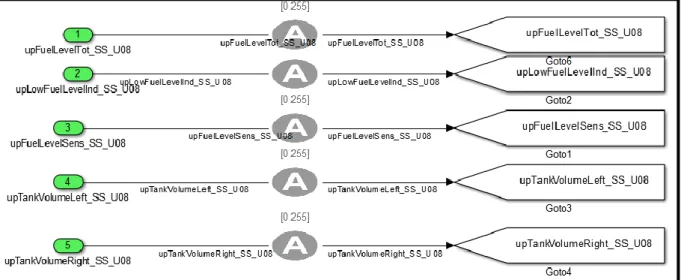
Parameter Status: upFuelLevelTot_SS_U08, upLowFuelLevelInd_SS_U08, upFuelLevelSens_SS_U08, upTankVolumeLeft_SS_U08, upTankVolumeRight_SS_U08 All the above inputs have their own ranges specified in AE201. The status values help in identifying whether the signal and parameters values are to be used in the algorithm. If the status is faulty, they are replaced with 0 or the last correct value within the input subsystem. The replacement blocks are shown in Figure 18.
Figure 18: Input Subsystem
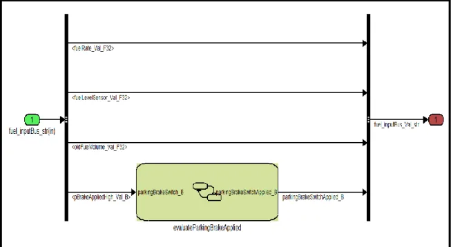
fuel_inputBus_Val_str above refers to a bus signal comprising of signals and their individual status whereas fuel_params_inputBus_SS_str refers to a bus signal comprising of parameters and their status. Another subsyetem visible in the above figure is the InputFilters subsystem which consists of the following subsystem to evaluate the application of the parking brake for 0.5 s with the help of a state diagram in Figure 19.
Figure 19: Evaluate parking Brake
5.1.1.2 Algorithm subsystem:
The algorithm subsystem consists of two subsystems depicted in Figure 20:
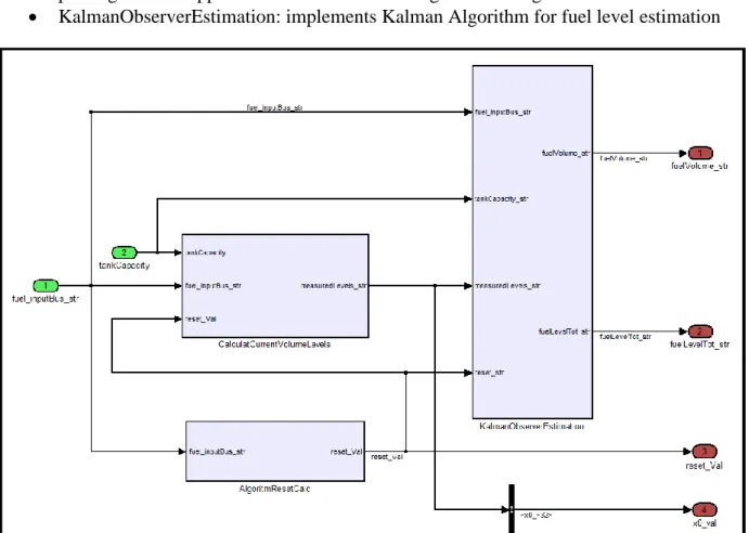
The lower subsystem is not considered since it implements the low fuel level warning function whereas only fuel estimation is catered to in this thesis which is implemented in the other subsystem. Sub block fuel level estimation algorithm in Figure 21 contains three sub blocks named CalculateCurrentVolumeLevels, AlgorithmResetCalc and KalmanObserverEstimation present in Figure 21.
CalculateCurrentVolumeLevels: calcuates fuel levels based on tank Parameters
AlgorithmResetCalc: prevents use of Kalman Algoritm when a refuel is detected after parking brake is applied for more than 5 s through a state diagram.
KalmanObserverEstimation: implements Kalman Algorithm for fuel level estimation
Figure 21: Fuel Level Estimation Algorithm
5.2 Transformation of requirements to Simulink Objects
The system architecture of the FLD as also illustrated in [30] is divided into various items namely COO, EMS and ICL as per their functionality at a vehicle level according to the recommendation of ISO26262. The safety and functional requirements in [30] are based on their overall functionality or operation. However, in this master thesis project, the requirements are mostly implementation specific with respect to the set of operations taking place in COO in Figure 16. There is one overall requirement on COO to check the accuracy of the fuel estimation. The Allocation Element Requirement document (AER201) defines a set of requirements which acts as a reference for our satisfaction criteria using SLDV. The requirements mentioned in AER201 are either functional requirements or operational requirements.
The approach followed towards verification of the Fuel Level Display System using SLDV required deep knowledge of the system to understand the requirements and map signals from requirements to system model. The theory behind the verification is based on the notion of contracts as illustrated in [30]. In [30], Westman et al. structured safety and functional requirements on a system with well-defined system boundary. The requirements to be verified on a system are “responsibilities between an environment and a system that are split into a guarantee
which models desired properties of a system, under the influence of an assumption, modeling expected properties of an environment.” The notion of contracts can be understood from Figure 22 where the requirement is represented as a contract of assumption (A) and guarantee (G):
Figure 22: Requirement as contract
The verification environment illustrated in Figure 23 is used for verifying the fuel level display system and more specifically the item COO. The approach followed is generic and can be applied to any verification activity for Simulink models.
Figure 23: Verification Environment
The different subsystem blocks that can be seen in the Figure 23 which also decide the nomenclature of the signals used throughout the verification process:
Input subsystem: models the input signals to the item (now called system) COO. These input signals are consistent to the input signals of the original system model are thus represented by their original signal names, ‘signalName’.
Environment Subsystem: models external virtual signals to the system to facilitate the verification of the overall functional requirement.
Overall functional requirement: The estimated fuel volume shall be within ‘x’ % of the actual fuel volume, given that the fuel sensor is within the actual fuel volume in ‘y’ %.
Assumption Subsystem: this block defines general constraints on the inputs signals and environment signals as defined by the requirement document AE201. These constraints are important for the verification to work effectively without traversing into those input values for which the system is not defined.
System model: reference to the original system model
Verification subsystem: Models additional assumptions and guarantees for each requirement separately as specified in the document AE201. The assumptions here are again on the input and the environment signals whereas the guarantees are on system output and internal signals. The verification subsystem also models some verification signals that are modelled as per the requirements and are used to verify whether the system signals are behaving in accordance with these verification signals.
One major distinction from [30] that is evident from the verification environment above is the separation of input and environment subsystems. Fundamentally, they both can be bundled together as ‘Environment’ according to the notion of contracts in [30] but are modelled separately in this thesis to keep consistency of usage of inputs in verification environment with the original system model.
Signal Nomenclature:
M_signalName: All signals starting with M_ are internal to the system model and are used
for satisfying proof objectives.
Eg: M_KalmanGain, M_parkingBrakeSwitchApplied_B, M_fuelLevelTot_Val_F32 etc.
V_signalName: All signals starting with V_ are verification signals Eg: V_levelWhenDetectionStarts_F32
signalName: These are virtual signals that are input to the system model. Eg: pBrakeAppliedHigh_SS_U08, fuelLevelSensor_Val_F32 etc.
E_signalName: All signals starting with E_ are environment signals created specifically to verify the overall system requirement. Eg: E_actFuelVol[inLit], E_actFuelVolinpercent
5.2.1 Assumptions
The assumptions are modelled for the input signals, parameters, their status and the environment signals. The assumptions here are general assumptions on signal ranges as per the document AE201. The dependencies between signals is also modelled within the Assumptions block shown in Figure 24. The assumption library block from SLDV illustrated earlier in Figure 8 can be seen throughout the modelling of assumptions in the following figures.
Figure 24: Assumtions on Signal Values, Verifiation Variables and Environment variables
The general assumptions are based on the signal ranges as per AE201. However, of particular interest are the modelling of dependencies. For example, the signals like fuelRate_Val_F32 (for fuel consumption) and E_actFuelVolinpercent (for actual fuel volume in %) are not independent to each other since fuel rate is the rate of consumption of actual fuel. Therefore their dependency is to be with the help of assumption blocks. A total of three such dependencies are modelled here:
fuelLevelSensor_Val_F32 with direct relation to actfuelLevelinPercent
V_actFuelVol[inLit] in relation to V_actFuelVolinpercent
fuelRate_Val_F32 in relation to V_actFuelVol[inLit]
Moreover the verification signal V_levelWhenDetectionStarts_F32 is modelled for verification of the requirement to check against the value in the model.
Apart from the above assumptions, there are assumptions on the signal status, parameters and their status depicted in the following figures:
Figure 25: Assumptions subsystem on Parameter Values
Assumptions subsystem on Signal Status:
Assumptions subsystem on Parameter Status:
Figure 27: Assumptions subsystem on Parameter Status
5.2.2 Resolving Compatibility
As earlier specified in the SLDV literature, all Simulink and MATLAB function blocks are not compatible with SLDV. They are to be replaced with compatible blocks with SLDV and then the verification process is carried out otherwise, these incompatible blocks are stubbed out during verification leading to unreliable results. Although, it is attempted to retain consistency with system model but some changes were made to cater to the compatibility issue. One such change is highlighted in the following figure.
Figure 28: Compatibility Issue with Original Block
The original system model made use of the user defined s-block Check Status FLAWLESS_B to check the status of the incoming signal and if found faulty, the signal value was replaced with the Replacement_val. However, this user defined s-block was found incompatible with SLDV. There were many instantiations of this block to check the status of other signals and parameters.
Figure 29: Compatibility replaced block
Therefore, the user defined s-block was replaced with the Check Status block as shown in Figure 29. The values ‘240’ and ‘256’ were used after studying the system documentation since the range 240-256 of the signal status was adjudged by the system as permissible or non-faulty. However, this activity of making changes may induce errors into the system model by the verification engineer and make the whole verification process useless.
The system architecture of the FLD as also illustrated in [30] is divided into various items namely COO, EMS and ICL as per their functionality at a vehicle level as per the recommendation from ISO26262.
5.2.3 Verification subsystem
This section illustrates the requirement modelling with additional assumptions for the requirement to hold. A detailed view of all the requirements is omitted here due to space limitation and only the important ones are illustrated. AER201_1, AER201_2 and AER201_3 are not within the scope of the Simulink implementation of system model.
AER201_5:
According to AER201_5, the estimation of the fuel level shall be carried out with a Kalman Algorithm using a Kalman gain of K=2.786*10-5.
The requirement imposes a guarantee on an internal model signal M_KalmanGain to be the specified value without mentioning any additional assumptions. So an initial verification mode for this requirement looked like in the following figure.
However, this led to the falsification of the proof objective with the counter example illustrated in Figure 31. After viewing the counter example in conjunction with the actual implementation of the system model in Figure 32, it was found that the selection of the Kalman Gain was dependent on fuel rate status (fuelRate_SS_U08) and wrongTankParameterSetting_B which is in turn dependent on inputs upTankVolumeRight_SS_U08 and upTankVolumeLeft_SS_U08. This was not mentioned in the requirement and could be found out only from the implementation.
Figure 31: Counter Example for AER201_5 Initial verification Model
Usage of only general assumptions allowed the above signals to take value 0 which made the proof objective to be falsified. As a result, the verification model was transformed as depicted in the following figures Figure 33 and Figure 34 by adding additional assumptions on the required signals.
Figure 33: AER201_5 Updated Verification Model Subsystem
Figure 34: AER201_5 Updated verification Model Implementation
The statuses were assumed to be within the ‘correct limits’ and then property could be verified. This is just one example where assumptions on signal status are not specified, many other requirements also face similar issues.
One may comment the utility of such verification process in which the requirement model is based on the system implementation and not on the requirement alone. This is true but with given requirements, system knowledge is required. However, this result can be used to comment on the quality of the requirement that it doesn’t specify all necessary information.
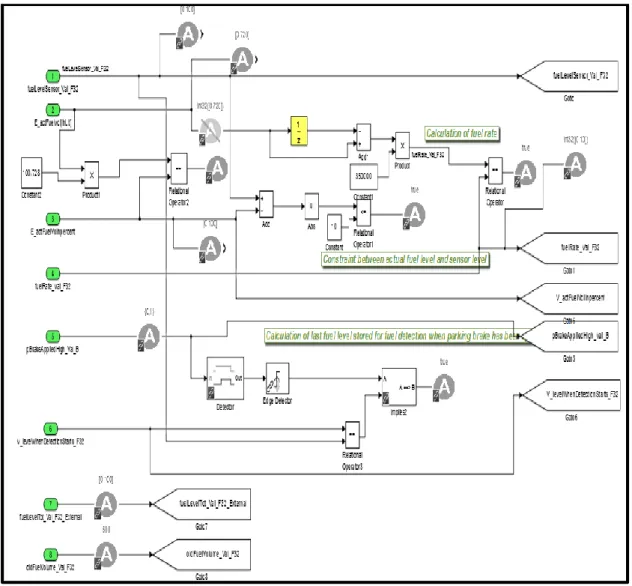
AER201_6:
This example illustrates the modelling of a more complex requirement:
Upon startup of the ECU an initial value, xstart, must be set. If the state saved from last
state shall be set to |FLS_vol|. Else the start-up state shall be set to the state saved from last shutdown.
Figure 35: Equations Governing Requirement AER201_6
Where:
usensor = Measured fuel level, |FLS_vol| [m3]
ufuelRate = Fuel consumption, fuelRate [m3/s]
𝑥̂ = Estimated fuel level [m3]
𝑥̂old = Estimated fuel level at last shutdown [m3]
Xstart = Initial state of fuel level estimation [m3]
Xtot = Measurable volume [m3]
Ts = Sample time [s]
y = Total fuel level, totalFuelLevel [%] K = Feedback gain [-]
F = Function converting m3 to corresponding %
The signals mentioned in the requirement are first mapped to the model signals:
xstart, Start up state: M_x0_f32
State saved from last shutdown: oldFuelVolume_Val_F32
|FLS_vol[in%]|: fuelLevelSensor_Val_F32 This is divided into 2 sub-requirements:
1. P6_1: If the state saved from last shutdown and FLS_vol differ by more than 10% or FLS_vol is above 90%, the start-up state is set to FLS_vol.
2. P6_2: Else the start up state is set to the state saved from last shutdown.
![Figure 1: Model based Design Workflow [4]](https://thumb-eu.123doks.com/thumbv2/5dokorg/4952670.136208/16.892.188.728.479.777/figure-model-based-design-workflow.webp)
![Figure 2: Simulation based Testing vs Formal Verification [9]](https://thumb-eu.123doks.com/thumbv2/5dokorg/4952670.136208/17.892.108.816.149.472/figure-simulation-based-testing-vs-formal-verification.webp)