Micro-Network Processor
A Processor Architecture for Implementing NoC Routers
Julia Martín Rovira
Francisco Manuel Fructuoso Melero
MASTER THESIS
2007
Micro-Network Processor
A Processor Architecture for Implementing NoC Routers
Julia Martín Rovira
Francisco Manuel Fructuoso Melero
Detta examensarbete är utfört vid Tekniska Högskolan i Jönköping inom ämnesområdet elektroteknik. Arbetet är ett led i teknologie
magisterutbildningen med inriktning inbyggda elektronik- och datorsystem.
Författarna svarar själva för framförda åsikter, slutsatser och resultat. Handledare: Shashi Kumar, Rickard Holsmark
Examinator: Shashi Kumar
Omfattning: 20 poäng (D-nivå)
Datum: August 22nd, 2007
Abstract
Abstract
Routers are probably the most important component of a NoC, as the performance of the whole network is driven by the routers’ performance. Cost for the whole network in terms of area will also be minimised if the router design is kept small. A new application specific processor architecture for implementing NoC routers is proposed in this master thesis, which will be called µNP (Micro-Network Processor). The aim is to offer a solution in which there is a trade-off between the high performance of routers implemented in hardware and the high level of flexibility that could be achieved by loading a software that routed packets into a GPP. Therefore, a study including the design of a hardware based router and a GPP based router has been conducted. In this project the first version of the µNP has been designed and a complete instruction set, along with some sample programs, is also proposed. The results show that, in the best case for all implementation options, µNP was 7.5 times slower than the hardware based router. It has also behaved more than 100 times faster than the GPP based router, keeping almost the same degree of flexibility for routing purposes within NoC.
Sammanfattning
Routern är en av de viktigaste komponenterna i ett “Network on Chip” (NoC), på grund av att nätverkets prestanda är direkt beroende av routerns prestanda. Kostnaden för utnyttjad area minskar också om routerns storlek minimeras. I denna rapport föreslås en applikationsspecifik processorarkitektur, kallad µNP (Micro-Network Processor), som router i ett NoC. Målet med µNP är att erbjuda en lösning som ger bra balans mellan hårdvarans prestanda och mjukvarans flexibilitet. Som stöd för arbetet med µNP, innehåller rapporten konstruktion av en hårdvarubaserad router samt en mjukvaruimplementerad router i en processor. I projektet presenteras första versionen av en µNP, med komplett uppsättning instruktioner samt exempel på program. Resultaten visar att µNP är 7,5 gånger långsammare jämfört med den hårdvaruimplementerade routern. Å andra sidan är µNP över 100 gånger snabbare än routern implementerad i mjukvara, med samma grad av flexibilitet för de uppgifter som en router kan behöva i ett NoC.
Acknowledgements
Acknowledgements
We would like to thank Professor Shashi Kumar for trusting in us and convincing us to extend our studies at Jönköping University for a second year, giving us the opportunity to take part in such a challenging project. We appreciate all the interesting discussions we have had with him and the insight in the world of research that he has given us through this project. We are also grateful for his patience and enthusiasm for the project.
Especial thanks to Rickard Holsmark for his supervision and support and for all the help he has provided us throughout the development of this Master Thesis. We would also like to thank Alf Johansson, head of the Master Program in Embedded Systems. He has been extremely helpful during all our education at Jönköping University, always caring for providing the students the highest standard teaching and helping us even after his working day.
We would like to acknowledge the excellent treat we have received from all the teachers within the Master Program in Embedded Systems. It has been very easy in all cases to have further discussions after the lectures and to get help during the laboratory projects.
We cannot forget to mention here our gratitude to all the members of the International Office at Jönköping School of Engineering. We got all the support from them when managing our acceptance the first year and then helping us with all the arrangements for prolonging our studies. They have always made us feel welcomed at the University.
And last, we would like to warmly thank our families for all their support and comprehension not only these years while in Jönköping, but through all our lives, being confident of our capabilities and making possible our international experience.
Key words
System on Chip (SoC) Network on Chip (NoC) Network
Router
Packet Switching Wormhole Switching Network Processor
Application Specific Processor Multithreaded Processor Performance Evaluation
Contents
Contents
1
Introduction ... 1
1.1 BACKGROUND... 1 1.2 PURPOSE/OBJECTIVES... 2 1.2.1 Latency... 3 1.2.2 Cost ... 4 1.2.3 Flexibility ... 5 1.3 LIMITATIONS... 5 1.4 THESIS OUTLINE... 62
Theoretical Background ... 8
2.1 NETWORK-ON-CHIP ARCHITECTURE... 8
2.2 NOCROUTERS... 9
2.2.1 Main Switching techniques... 9
2.2.2 Routing Algorithms... 11
2.2.3 Design Options for a NoC Router... 11
2.3 NETWORK PROCESSORS... 12 2.4 MULTITHREADED PROCESSORS... 14 2.4.1 Blocked Multithreading... 15 2.4.2 Interleaved Multithreading ... 15 2.5 VLIWPROCESSORS... 15
3
Hardware Router ... 17
3.1 SPECIFICATIONS:QNOCPROJECT... 17 3.2 DESIGN... 20 3.2.1 Architecture ... 20 3.2.2 Handshaking Protocol ... 25 3.2.3 Packet Format ... 263.3 HARDWARE ROUTER TESTING... 28
4
Router using a GPP Core ... 29
4.1 GPPCHOICE:LEON VS MICROBLAZE... 29
4.2 ROUTER DESIGN USING MICROBLAZE PROCESSOR... 31
4.3 SOFTWARE ROUTER TESTING... 35
5
µNP: Design of an ASP ... 36
5.1 ARCHITECTURAL OPTIONS:VLIW VS.MULTITHREADED... 36
5.2 µNPARCHITECTURE... 37
5.2.1 Multithreaded Processor with 6 threads... 37
5.3 PROCESSOR DATA PATH... 38
5.3.1 Register File... 38
5.3.2 Output Structure ... 40
5.3.3 Pseudo-random number generator ... 41
5.3.4 Status Registers ... 42
5.3.5 Input structure... 42
5.3.6 Special purpose registers... 43
6.1 ADDRESSING MODES AND INSTRUCTION OPERANDS... 46
6.2 INSTRUCTION SET... 47
6.2.1 Arithmetic and Logic Instructions ... 47
6.2.2 Load and Store Instructions ... 50
6.2.3 Branch Instructions ... 51
6.2.4 Routing Instructions ... 52
6.2.5 Thread Activation Instructions ... 53
6.3 SCHEDULER AND CONTROL SIGNALS... 54
6.4 EXAMPLE PROGRAMS FOR µNP... 57
7
Evaluation and Comparison... 62
7.1 PERFORMANCE... 62
7.1.1 Evaluation Methodology... 62
7.1.2 Results: Hardware Router ... 72
7.1.3 Results: GPP based Router... 76
7.1.4 Estimates for µNP ... 77 7.1.5 Comparison of results... 78 7.2 FLEXIBILITY... 80
8
Conclusions... 82
8.1 CONCLUSIONS’SUMMARY... 82 8.2 FUTURE WORK... 83 8.2.1 Architectural Improvements... 83 8.2.2 µNP Evaluation ... 84 8.2.3 Development Tools ... 849
References ... 85
10
Appendix... 87
10.1 INSTRUCTIONS IN ALPHABETICAL ORDER... 88
List of Figures
List of Figures
FIGURE1.1: LATENCY GRAPH ... 3
FIGURE1.2: COST VS. PERFORMANCE GRAPH ... 4
FIGURE1.3: FLEXIBILITY VS. PERFORMANCE GRAPH ... 5
FIGURE 2.1: 4X4 MESH TOPOLOGY FOR NOC... 8
FIGURE 2.2: ARCHITECTURE OF POWERNP. TAKEN FROM [7] ... 13
FIGURE 2.3: MULTIPLE FUNCTIONAL UNITS SUPPORT VLIW. ... 16
FIGURE 3.1: QNOC ROUTER ARCHITECTURE, TAKEN FROM [11] ... 18
FIGURE 3.2: HARDWARE ROUTER ARCHITECTURE MODIFIED FROM [11]... 18
FIGURE 3.3: BLOCK DIAGRAM OF THE INPUT COMPONENT... 21
FIGURE 3.4: BLOCK DIAGRAM OF THE OUTPUT COMPONENT. ... 23
FIGURE 3.5: HARDWARE ROUTER INTERFACE ... 23
FIGURE 3.6: INTERCONNECTION BETWEEN INPUT AND OUTPUT COMPONENTS... 24
FIGURE 3.7: PROTOCOL BETWEEN AN OUTPUT OF ROUTER A AND AN INPUT OF ROUTER B... 25
FIGURE 3.8: FLIT FORMAT... 26
FIGURE 4.2: BLOCK DIAGRAM OF MICROBLAZE. TAKEN FROM [13]... 30
FIGURE 4.3: BLOCK DIAGRAM OF THE SYSTEM SIMULATED. MODIFIED FROM [13] ... 32
FIGURE 4.4: NEW FLIT FORMAT REQUIRED FOR MICROBLAZE... 32
FIGURE 4.5: DESCRIPTION OF THE MAIN PARTS OF THE SOFTWARE FOR THE INPUTS... 34
FIGURE 4.6: DESCRIPTION OF THE MAIN PARTS OF THE SOFTWARE FOR THE OUTPUTS. ... 35
FIGURE 5.1: BLOCK DIAGRAM OF MULTIPLE PC BASED ARCHITECTURE. ... 38
FIGURE 5.2: REGISTER FILE DIAGRAM... 39
FIGURE 5.3: BLOCK DIAGRAM OF THE OUTPUT STRUCTURE. ... 40
FIGURE 5.4: PSEUDO-RANDOM NUMBER GENERATOR... 42
FIGURE 5.5: BLOCK DIAGRAM OF THE INPUT PORTS STRUCTURE. ... 43
FIGURE 6.1: HARDWIRED SCHEDULER. ... 55
FIGURE 6.2: BLOCK DIAGRAM OF THREAD SCHEDULER... 57
FIGURE 6.3: CODE FOR µNP IMPLEMENTING A COMPLETE PROGRAM WITH XY ROUTING... 59
FIGURE 6.4: MODIFIED CODE FOR µNP TO IMPLEMENT ODD-EVEN ALGORITHM ... 61
List of Figures
FIGURE 7.3: INCOMING PACKETS FROM (A)EAST; (B)NORTH; (C)WEST; (D) SOUTH... 66
FIGURE 7.4: BEST CASE FOR A PACKET BEING SENT (NO CONGESTION)69
FIGURE 7.5: COMMUNICATION AND DELAY IN BEST CASE (1) AND
WITH CONGESTION (2) ... 70
FIGURE 7.6: DELAY AND EXPECTED COMMUNICATION (1) REAL
SITUATION (2) ... 71
FIGURE 7.7: DELAY AND COMMUNICATION AT A SLOWER RATE THAN CAN BE HANDLED ... 71
FIGURE 7.8: GRAPHICAL RESULTS FOR HARDWARE ROUTER UNDER THE FIRST AND SECOND TEST APPROXIMATIONS ... 74
FIGURE 7.9: GRAPHICAL RESULTS FOR HARDWARE ROUTER UNDER THE SECOND TEST APPROXIMATION AND THE REAL VALUE. ... 75
FIGURE 7.10: GRAPHICAL RESULTS FOR THE GPP BASED ROUTER FOR THE REAL PACKET INJECTION RATE. ... 76
FIGURE 7.11: (A) HARDWARE ROUTER LATENCY PLOT (B) GPP
BASED ROUTER LATENCY PLOT ... 79 FIGURE 8.1: LATENCY PLOTS FOR HARDWARE AND GPP BASED NOC
List of Tables
TABLE 1.1: µNP DESIRED CHARACTERISTICS ... 2
TABLE 3.1: HARDWARE ROUTER CHARACTERISTICS ... 19
TABLE 3.2: XY ROUTING RESULTS. ... 22
TABLE 3.3: BIT CODES FOR FLIT TYPES ... 26
TABLE 3.4: BIT CODES FOR DIFFERENT ORIGINS... 27
TABLE 5.1: LIST OF SPECIAL REGISTERS, THEIR SIZE AND PURPOSE ... 45
TABLE 6.1: ABBREVIATION LIST FOR INSTRUCTIONS’ SYNTAX ... 46
TABLE 6.2: SYNTAX FOR SUBTYPE A INSTRUCTIONS ... 47
TABLE 6.3: LIST OF SUBTYPE A INSTRUCTIONS... 48
TABLE 6.4: LIST OF SUBTYPE B INSTRUCTIONS... 48
TABLE 6.5: SYNTAX FOR SUBTYPE B INSTRUCTIONS ... 49
TABLE 6.6: SYNTAX FOR SUBTYPE C INSTRUCTIONS... 49
TABLE 6.7: LIST OF SUBTYPE C INSTRUCTIONS... 49
TABLE 6.8: LIST OF LOAD AND STORE INSTRUCTIONS ... 50
TABLE 6.9: SYNTAX FOR LOAD AND STORE INSTRUCTIONS... 50
List of Tables
TABLE 6.11: SYNTAX FOR FULL REGISTER BRANCH INSTRUCTIONS... 52
TABLE 6.12: SYNTAX FOR THE BITWISE BRANCH INSTRUCTION ... 52
TABLE 6.13: LIST OF BRANCH INSTRUCTIONS ... 52
TABLE 6.14: LIST OF LOAD AND STORE INSTRUCTIONS ... 53
TABLE 6.15: SYNTAX FOR LOAD AND STORE INSTRUCTIONS ... 53
TABLE 6.16: LIST OF LOAD AND STORE INSTRUCTIONS ... 54
TABLE 6.17: SYNTAX FOR LOAD AND STORE INSTRUCTIONS ... 54
TABLE 6.18: HARDWIRED CONTROL TABLE FOR µNP... 56
TABLE 7.1: RESULTS FOR HARDWARE ROUTER UNDER TEST CASE 1... 72
TABLE 7.2: RESULTS FOR HARDWARE ROUTER UNDER TEST CASE 2... 73
TABLE 7.3: COMPARISON BETWEEN REAL AND INTENDED INJECTION RATES. ... 75
TABLE 7.4: PERFORMANCE RESULTS FOR THE GPP BASED ROUTER ... 77
List of Abbreviations
µNP: Micro-Network Processor
ASIC: Application Specific Integrated Circuit ASIP: Application Specific Instruction Processor ASP: Application Specific Processor
BDY: Body Packet
CRT: Current Routing Table CSIP: Currently Service Input Port DSP: Digital Signal Processor EDK: Embedded Development Kit EP: End Packet
FP: Full Packet
GPP: General Purpose Processor HW_R: Hardware Router
ILP: Instruction Level Parallelism IP: Intellectual Property
ISA: Instruction Set Architecture LFSR: Linear Feedback Shift Register NBS: Next Buffer State
NoC: Network on Chip NP: Network Processor PC: Program Counter QoS: Quality of Service
RISC: Reduced Instruction Set Computer RNI: Resource Network Interface
SoC: System on Chip SW_R: Software Router TLP: Thread Level Parallelism VCT: Virtual Cut Through
VLIW: Very Large Instruction Word VLSI: Very Large Scale Integration
Introduction
1 Introduction
1.1 Background
Network-on-Chip (NoC) is a relatively new research field within System-on-Chip (SoC). Before NoC was considered, Intellectual Property (IP) cores were connected among each other through buses. This option is costly when many IP cores want to be interconnected and becomes very complex. Dedicated architectures and on-chip designs cannot support current development requirements and time-to market, that is why reusable components and scalable solutions are of great importance, [1]. Therefore, taking some ideas from computer networks, for the NoC approach, IP cores were connected to a network of routers to allow the exchange of information between them. Such platform (NoC) architecture and design methodology is proposed in [1].
The router is considered to be the most important component in any network. Therefore, it can also be stated that a router is the most important part of a NoC. A router’s job is to help deliver information (packets) from one IP core to another within the NoC. Routers are therefore interconnected with other routers and with one or many resources within the network. In the case of mesh topologies, the most widely used for NoC, the number of routers is equal to the number of IP cores.
Routers are the bottleneck of a NoC and as networks tend to be homogeneous (all routers in the network will most likely have the same design), if the performance of a router design is optimized, then the whole network’s performance will be increased.
As have been discussed, NoC borrowed some ideas from computer networks, so it seems appropriate to do the same now to try to improve NoC’s performance. Network Processors (NP) are specific purpose processors used for implementing routers in computer networks and can therefore become an inspiration for an on-chip router design. Such router design is the goal of this Master Thesis, and will be called Micro-Network Processor (µNP).
µNP will be designed as an ASP (Application Specific Processor) as high performance and small area is expected for the design. If a GPP (General Purpose Processor was used, the degree of flexibility achieved could be very high but the latency when routing and the area of the processor would be much larger than required for this application, as will be discussed further in this chapter.
1.2 Purpose/Objectives
The main goal of this project is the following:
• To design the architecture of a specific purpose processor to be the
router of a NoC.
Nowadays, the most common implementations of routers in any interconnection network are done fully in hardware or by using a General Purpose Processor (GPP). For NoC, hardware designs have mostly been used, and the option of using a GPP has not been common so far. The aim of this thesis will be to design an Application Specific Processor (ASP) that can replace both hardware and GPP based routers offering more advantages.
The design of such a processor requires some initial parameters to be decided upon. Therefore, the most important characteristics of the design so that it can replace previous designs will be established. They are summarized in table 1.1.
µNP Characteristics Characteristics Characteristics Characteristics
Simplicity Small in area Little packet latency Routing algorithm flexibility
Protocol flexibility
Table 1.1: µNP Desired characteristics
Those characteristics will be divided into three main groups: Cost, Latency and Flexibility.
In the following subsections a comparison between the three main groups of router implementations will be discussed. In all of them SW_R (Software Router) refers to the GPP and data related to it is represented in red, µNP refers to the ASP to be designed in this Master Thesis and data related to it is represented in blue. HW_R (Hardware Router) refers to a router implemented in hardware and data related to it is represented in green.
Introduction
1.2.1 Latency
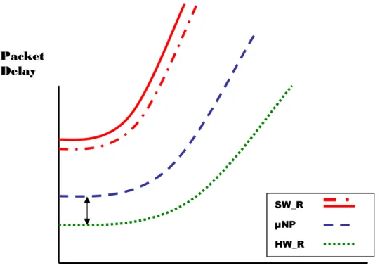
Latency of packets should be small. It is important for the performance of network that the performance of a single router is also as high as possible. This performance will be high when the time that a packet requires to go from its origin to the destination is minimal. This time will be called the delay of a packet or latency. The representation of the expected packet delay vs. the packet injection rate at which the packets are being generated in the network or latency plot is shown in figure1.1.
It can be seen that the lowest latency and, therefore, the highest performance is expected from a router fully implemented in hardware. This is due to the fact that the hardware design can be optimized for sending packets and these routers can process a packet in a few clock cycles.
The objective of this Master Thesis is that µNP’s latency can be kept as close to the one of a hardware router as possible, which is shown by the black arrow in figure1.1. It is also expected that µNP’s performance will be higher than the one of a GPP as the ASP will provide with an instruction set that will speed up the routing software.
Figure 1.1: Latency graph Packet
Delay
Packet Injection Rate
SW_R µNP HW_R
In figure1.1, two different red lines can be seen for a software router. The explanation is simple; depending of the software used for routing the packets, different levels of performance can be achieved. Given the fact that the continuous line represents a routing program written in C, it can be assumed that if the program is translated into Assembly language then the performance could be improved and then it would be represented by the dotted line.
1.2.2 Cost
The µNP should be simple and small in area, which means that its cost needs to be as low as possible. To illustrate this property, figure1.2 is presented.
In the graph shown in figure1.2, it can be easily seen that a router implemented fully in hardware will present minimum cost as the hardware is optimize to just route packets, the area used is minimal.
It can also be appreciated that we have assumed that a GPP will have less cost than the ASP to be designed. This is due to the fact that such GPP would probably have gone through a thorough development process that may have last several years and produced several versions. µNP, in this first version will probably not achieve such optimization. However, GPPs provide their users with quite a lot of memory, which is not needed for a NoC router, which will contribute to a smaller cost of µNP.
Figure 1.2: Cost vs. Performance graph Cost SW_R µNP HW_R Performance µNP+M SW_R+M
Introduction
1.2.3 Flexibility
Both in a software router and in µNP, different communication protocols and routing algorithms can be loaded as software. This provides great flexibility for these types of routers, whether a hardware router will just be able to serve the purpose for which it was designed, and if some change is to be made a new router needs to replace the old one. The graph showing the flexibility vs. the performance for the three types of routers is in figure 3.
In figure1.3, the software router presents even more flexibility than µNP. As µNP is an Application Specific Processor, it will be designed for serving to the purpose of routing packets, while a GPP has not a single application and therefore is more likely to support a wide variety of programs for different uses.
Figure 1.3: Flexibility vs. Performance graph
1.3 Limitations
In this Master Thesis two different phases of the project have been developed. In the first phase a study of a possible design of both a hardware based router and a software coded in a processor to route packets has been conducted. The aim of doing such study before actually developing the core of this project was to gain a better understanding of different implementation options for NoC routers as well as to obtain some data that may help to evaluate the design carried out in the
Flexibility
SW_R
µNP
HW_R
The second part of this Master Thesis, and the real goal, was to create from scratch a specific purpose processor that could perform as a router for NoC. In this part just a conceptual design and the schematics for the processor will be provided, as the development of a software model for the proposal and possible hardware implementation are not part of the scope of this Master Thesis.
It also needs to be taken into account that in this first version of the µNP the main concern was to get a simple design and to find a suitable architecture that could be used for routing purposes with the highest performance possible. Therefore, there will be room for improvements in the design and future versions of the processor may be developed including such improvements.
Unfortunately it has not been possible to collect the necessary data for developing an evaluation in terms of cost. This will be proposed as a future work.
1.4 Thesis outline
After this introduction, the main theoretical concepts required to understand the contents of the thesis are described in chapter 2.
In this Master Thesis there are three main parts. In the first part the study and design of a hardware router was conducted. The information related to that part can be found in chapter 3, where the specifications of the design and the design itself is discussed, as well as thee general validation process followed.
In the second part of this Master Thesis the study and design of a software router were carried out. In chapter 4 the work conducted for this second part is explained. A discussion of which General Purpose Processor was used, a description of the code written to route the packets and the verification process for the design are included.
The third part is the core of this report and corresponds to the design of the µNP. In chapter 5 the design decisions and the final architecture are described and chapter 6 is dedicated to discuss the instruction set of our ASP proposal, several subsections are used to group the instructions, and to describe the control signals and provide with some examples of code for the new architecture as a way of verifying the design.
The evaluation methodology which was followed throughout the project and its application to the three designs is explained in chapter 7. In the same chapter, the results of the evaluation are presented as well as the comparison of the obtained results is established. Conclusions are drawn in chapter 8 together with a discussion about future work related to this Master Thesis and chapters 9 and 10 contain the reference list and the appendix list respectively.
2 Theoretical Background
2.1 Network-on-chip Architecture
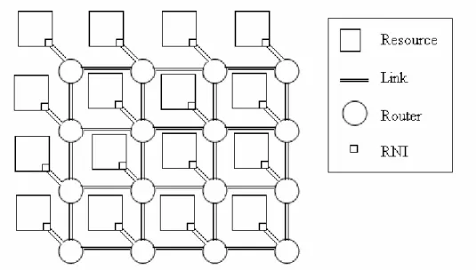
As it is explained in [2] placing an on-chip interconnection network, instead of a design specific wiring, facilitates modular design. This is due to its structured design. Modularity contributes to using high-performance circuits in order to reduce the latency and therefore to increase the bandwidth within the network. All the NoC architectures present mainly the same components, which are the resources (or network clients), with their network interface (RNI), the routers and the links.
Figure 2.1 presents a NoC architecture that has a 4x4 mesh topology as the routers are placed in a square. Mesh topology is the most commonly used for NoC and that is going to be assumed in this Master Thesis. This topology allows making the routing decisions functions simple and identical for all the routers within the network, as stated in [3].
Figure 2.1: 4x4 mesh topology for NoC
The resources of the network may vary depending of the design from a wide range of IP cores. Such cores can be, for example, memories, DSPs (Digital Signal Processor) or other kinds of processors, controllers, programmable logic blocks…etc.
Theoretical Background
Resources are linked to a router through a RNI (Resource Network Interface). The mission of the RNI is to facilitate the correct communication between a resource and the router connected to it. Even though the network may share a single clock, it is very likely that the resources will have a different timing, they are usually slower, and then it is also required that the router’s communication protocol is followed by the resources. Thanks to the RNI, the resources are seeing as another router sending packets by the router connected to them, favouring the router’s homogeneous behaviour and simple design.
The routers are small and simple components within the chip, as most of the space is preferably dedicated to IP cores. The routers for NoC are further discussed in the next section.
2.2 NoC Routers
In NoC designs, the most important parts of the network that interconnects all the IP blocks are the routers. These routers have the duty of sending the packets between the different IP blocks in the NoC. In order to make this task, they have to route the information, in form of packets, according to some routing algorithm. There are two main routing techniques which are static and adaptive (also known as dynamic). In the static routing, the paths from one point in the network to another are fixed, and usually only one path is allowed, being all the packets sent through this path. There is no possibility of another path for the packets. Using this technique there is not any chance for deadlocks, unless errors occur in the routers, but the adaptability of the network to different situations such as traffic status is non-existent.
With the adaptive routing, the paths followed for the packets from one point of the network to another can change dynamically throughout the time, according to some parameters, as for example the traffic situation in the network. This technique is more complex and dangerous since, if it is not implemented carefully, it can lead for example to deadlock situations.
The routers being the most important part of the network, the design of those is a key factor affecting the performance of the network and this design is very much influenced by the switching technique that is to be supported [4].
2.2.1 Main Switching techniques
• circuit switching • packet switching
• virtual cut-through (VCT) switching • wormhole switching.
In circuit switching the path from the source to the destination is reserved before the transmission of data is started. This is done with the help of a header flit, which contains the destination of the data, which is sent through the network until the destination is reached, and all the links where this flit has passed through are reserved for the transmission of the rest of the message.
In packet switching, also known as store-and-forward, all the packet is sent at the same time and buffered in the intermediate nodes of the path until the packet reaches the destination. The first few bits contain the information regarding the destination and possibly other fields for control and routing issues. This way, only one link between routers (channel) currently dealing with the packet is busy at a time, due to a particular message in the whole network.
While in packet switching the message cannot be forwarded until the whole packet has been received, with virtual-cut-through techniques the packet can be split into many parts called flits.
The first flit usually contains the information needed for the routing of the message and when it arrives to a node, it can be sent to the next node without having to wait for the next flit to arrive. The path that this flit is passing through is reserved for the next flits of the message in a way such that they do not have to wait for routing decisions, following the path that has been reserved by the first flit, also known as header flit.
A particularity of this technique is the size of the buffer, that as in packet switching, it is able to store all the flits belonging to the same message, in such a way that if the header flit encounters a stall in its way to the destination, all the message can be stored in the same node.
In wormhole switching the message is also split into flits and these flits are also pipelined through the network until the destination, but the main difference with VCT is the size of the buffers in the nodes. Using this technique, the buffers do not have capacity to store all the flits of the message, instead they are very small in size, allowing only a few flits being stored in the same node.
If the header flit encounters a stall in the path, all the others flits remain in the same place where they were until the header flit can proceed. This way, all the path is blocked for other messages that want to use some channel that is busy by the first message.
Theoretical Background
other hand, a disadvantage of wormhole switching is the probability of deadlock. With this algorithm there is a risk that a packet encounters a situation in which some outputs are blocked and pending on inputs which are also block in a manner that is not possible to be solved without taking measures such as packet or flit drop.
2.2.2 Routing Algorithms
In this section we are going to explain the two different routing algorithms that have been used during this master thesis. The first one is a static routing algorithm known as “XY” where the packets are routed depending on the relative position of the destination and where they are. This way, the first dimension to be routed is the X dimension, so if the destination is in another column of the network supposing a mesh topology, the packet would be routed through along the file where it is in that moment. If the X dimension is already reached, the packet would be routed in the Y dimension, otherwise it means that the packet has reached its destination and therefore it is sent to the local resource.
The second one is a dynamic routing algorithm known as “Odd-even”[5]. This algorithm is intended to route packets in a non-deterministic fashion but preventing it from deadlock situations. The main idea is that some turns are prohibited in this model, ensuring that the packet can not enter in such situations. A possible implementation of that algorithm that we have used in the development of this work, is not to allow packets coming from North or South inputs to be routed through the West output if the router is placed in a odd column, and not to allow packets coming from East input to be routed through the North and South outputs.
Following this rules, it is impossible, as discussed in [5], that situations of deadlock can arise.
2.2.3 Design Options for a NoC Router
Regarding the design of NoC routers there are two main options, depending on the complexity and purpose of these.
The first option is a router designed completely in hardware. These routers are very small and provide a high performance due to the fact that the hardware has been specifically designed for this purpose. The main drawback is the high cost of development and the small degree of freedom that these routers provide, since if some parameter of the design has to be changed the router itself has to be removed and a new one has to be designed.
programmed using software, typically a processor that can be from very generic purpose to very specific. If the processor is very specific it is known as Application Specific Processor, and the performance can be very high but the degree of freedom can be a little bit more reduced than with a general application processor. The main advantages of this type of router are the flexibility and the cost, since the same design can be used for many different routing and switching techniques and the time and cost of development of new software is much lower.
Up to now, the possibilities of using a specific purpose processor to act as a NoC router have not been widely explored. This will be the purpose of this Master Thesis.
2.3 Network Processors
Network Processors (NP) are chips which can be programmed using software as general microprocessors. The difference is that these chips are optimized for some applications related with the networks and essentially the packet processing tasks [7]. Usually, this is done with a software programmable device and some special circuitry that achieve a high performance in packet processing.
The main advantages of these architectures are the flexibility, which is quite similar to a General Purpose Processor (GPP) but limited to the normal functions and requirements of network processing tasks, and the time to market and cost, which are lower than other solutions as for example Application Specific Integrated Circuit (ASIC).
ASIC solutions, as mentioned before in section 2.2, have a lack of flexibility and a big time to market, since implementing a new functionality means to change the complete product, to design the new ASIC which is very costly, to implement it and to place it. Due to these facts, it is not surprising that Network Processors replace ASIC solutions in new network equipment, but ASIC still has some advantages over NP, especially the performance. ASIC solutions can achieve a very high performance in terms of latency and throughput. This is a key factor in new and future networks where speeds of hundred of Gbps are to be achieved.
Other options used by the industry for network equipment have been GPP and FPGA based solutions. GPP allow great flexibility as any function can be implemented by software, but the main drawback is the poor performance that is achieved, since the instructions and the architecture are not intended for the specific issues of network applications.
FPGA solutions also have very good flexibility properties, since the design can be changed, but the time to market is bigger, because the design of new hardware with today’s level of abstraction is costly and the performance is still far from what can be expected with ASIC.
Theoretical Background
NP can have different architectures, as many as vendors. Many of them use Application Specific Instruction Processor (ASIP) with some other components as co-processors and small hardwired designs for very specific tasks and a GPP in order to manage the whole system. This design can change, depending on the vendor, from many co-processors and one ASIP to several ASIP and many hardwired components.
In figure 2.2 the main components of the IBM’s network processor PowerNP can be observed. It consists of the Embedded Processor Complex (EPC), special processing hardware and peripheral interfaces. The EPC is made of 16 programmable protocol processors and a PowerPC processor together with many different hardware accelerator units. More details about this Network Processor can be found in [6]. Details of some other commercial products can be found in [7].
Figure 2.2: Architecture of PowerNP. Taken from [7]
Regarding the applications of NP, there are some domains where NPs have already shown benefits, [8]:
• Content switching and load balancing. When the load on the server side is very
• Traffic differentiation. In order to achieve some QoS (Quality of Service),
differentiation of traffic is a key factor allowing the classification of current traffic.
• Network security. NP can encrypt and act as a firewall. Due to its flexibility is
very appropriate for these tasks, as this is an ever evolving domain.
• Terminal mobility. As all the protocols are likely to change and evolve during
the next years and continue to increase in complexity, NP is a perfect solution enabling short time to market products compliant with the new protocols.
• Active networks. In active networks, the packets are not merely forwarded, but
they can change the behaviour of the router depending on their data. This can only be done with programmable devices, and NP are the most appropriate for that.
2.4 Multithreaded Processors
A possible solution for hiding latency could be to implement multithreading supported by hardware [9]. It consists of several threads of execution that are independently invoked. Each thread has a state associated to it, composed at least by processor registers and program counter, but which can also include all the information which is relevant from a thread and that is not shared by other threads.
Every time the execution changes from one thread to another, the state of the current thread, also called context, needs to be saved and the context of the new thread needs to be restored. This process is known as context switching.
Context switching is costly in terms of execution time, especially in hardware-supported shared address space and even more in the case of systems where a single processor is used. This is why hardware support is required instead of storing the context in memory by means of software [9].
The effect of context switching in the processor utilization time can be observed in equation 1, where Busy is the time threads spends executing, Switching is the time spent in changing the context from one thread to another and Idle is the time when no thread was in execution in the processor. It can be deducted, that in order to obtain full utilization of the processor, no idle time and negligible switching time will be required.
Idle Switching Busy Busy n Utilizatio + + = (1)
There are two main techniques to implement multithreading according to [9], i.e. blocked multithreading and interleaved multithreading.
Theoretical Background
2.4.1 Blocked Multithreading
Usually there are several hardware register files and program counters that are assigned to those threads that are active, currently being executed, at the moment. Therefore, the number of active threads is limited by the available copies of hardware resources.
The threads that are neither executing nor blocked, but that are eligible to be executed as soon as hardware resources become available are called ready threads. This type of multithreading is based on switching the context from an active thread to a ready thread once the current thread in execution is blocked due to the occurrence of a long latency event. An active thread will be then executing while no such long latency event takes place, which can be due to a cache miss or an instruction requiring several clock cycles to be executed.
2.4.2 Interleaved Multithreading
This approach tries to reduce the processing time consumption caused by context switching overhead by actually removing it completely, given the fact that there are enough concurrent threads to completely hide the latency.
Each clock cycle, a new thread is executed from the pool of ready threads with a hardware context (ready and active). If a thread incurs in a long latency event, the thread is removed from the ready pool (active but not ready) and is not considered ready until the long latency event has been completed.
2.5 VLIW Processors
Simple scalar processors are those processors that execute one instruction at a time. In order to increase the performance of such processors, it is possible to exploit the parallelism present in some parts of the code, known as Instruction Level Parallelism (ILP).
VLIW (Very Large Instruction Word) processors are those which present a specific architecture so that one of their instructions is composed by several smaller instructions. Such instructions are known as MultiOp or multi- operations [10]. MultiOps can combine logical, arithmetical and control operations according to the available hardware resources.
VLIW processors present several functional units that make possible the parallel execution of multiple operations. MultiOp instruction words are therefore typically composed by one operation per functional unit present in the processor, as shown in figure 2.3.
Figure 2.3: Multiple functional units support VLIW.
VLIW approach is quite complex, especially in terms of finding the parallelism. It is the duty of the compiler to analyse the program to be executed and to schedule operations to obtain the maximum performance from the available hardware resources, in order to achieve the highest utilization feasible and to keep the program integrity.
As there are some instructions that are dependent from previous instructions, it is very important that the compiler is able to detect such dependencies to make sure that the result obtained is the desired one. Therefore, there will be some occasions in which some of the operation fields within the instruction word may be left blank.
Instruction word
Adder Comp Mult Adder
Hardware Router
3 Hardware Router
In this chapter, the study and design of the hardware router is described. The obtained results will be used to compare the router with the other router designs developed through the Master Thesis.
The router architecture described in the QNoC project [11], will be mostly reused, as well as the concepts applied on it. A simplification has been made as the aim of this chapter of the Master Thesis is to acquire some experience in router implementation and design in order to develop a better solution for the µNP. Developing a new router architecture is a very time consuming process and was out of the scope of this thesis.
The implementation of the hardware router based on the QNoC will be done in VHDL. The results from simulation will be used for establishing a comparison with the results that will be obtained when testing the µNP (Micro-network processor).
3.1 Specifications: QNoC Project
The QNoC project stands for “QoS architecture and design process for NoC”. Within this project, a customized architecture for NoC was designed in order to solve the problems of VLSI SoC and therefore minimizing cost in terms of area and power but still maintaining an adequate QoS [11]. The specification of the hardware router that has been developed as part of this thesis is based on the QNoC router architecture shown in figure 3.1.
There are four different services defined in QNoC.
• Signalling • Real-Time • Read/Write • Block Transfer
It can be observed that different virtual channels have been created depending on the type of information received, which are called services.
Figure 3.1: QNoC router architecture, taken from [11] Our proposal for a hardware router design is shown below in figure 3.1.
Figure 3.2: Hardware router architecture modified from [11]
Hardware Router
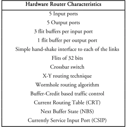
Table 3.1 summarises the list of main characteristics of the implementation of the hardware router.
Hardware Router Characteristics Hardware Router Characteristics Hardware Router Characteristics Hardware Router Characteristics
5 Input ports 5 Output ports 3 flit buffers per input port
1 flit buffer per output port
Simple hand-shake interface to each of the links Flits of 32 bits
Crossbar switch X-Y routing technique Wormhole routing algorithm Buffer-Credit based traffic control
Current Routing Table (CRT) Next Buffer State (NBS) Currently Service Input Port (CSIP) Table 3.1: Hardware Router Characteristics
The motivation of the different design decisions taken, in order to simplify and reuse the QNoC architecture, is discussed in the following paragraphs.
A 5-input 5-output router was chosen so that the router can be used in a 2D Mesh topology. The Resource Network Interface (RNI) is considered to be of the same type as an interface of any other router in the network. Credit based hand-shake interface will be considered sufficient for establishing the communication between routers.
We have considered that 32 bit flits is a common length for a flit. With this type of flits, the size of the input and output buffers and by using wormhole routing technique we aim to keep the size of the router small.
The credit based control will be used in order to know when the flits can be sent from the output of one router to the input of another router or to a resource. For this, CRT, NBS and CSIP will be used.
The CRT is used so that the number of the output port for the corresponding flit is stored until the whole packet has been sent. This is done in order to route the packet just once and then send all the flits of that packet trough the same route.
In NBS the number of available flit slots in the input buffer of the next router is stored. The value of the NBS is decremented when a flit is sent. When a flit is sent by a router it will send a buffer-credit signal to its neighbours so that the value of their NBS can be decremented.
In CSIP the current state of the output round-robin scheduling is stored. The number stored in CSIP is incremented when the transmission of a packet is finished or if there is nothing to transmit in an input.
3.2 Design
3.2.1 Architecture
The design of the hardware router has been done using VHDL as hardware definition language.
We have chosen an architecture in which we divide the router into two main components: input and output. Due to the fact that the proposed router will present five inputs and five outputs, the final router will be result of assembling five inputs with five outputs, using the facilities of VHDL to create a hierarchy of components and interconnect them. The whole system will be fed by a single clock signal.
The reason why we can independently design one input and one output and then just replicate and assemble the components, is the fact that VHLD provides process concurrency. Each component in VHDL is formed of one or several processes. Such processes execute concurrently every clock cycle. Therefore, a hardware router will be able to independently manage all its inputs and outputs at the same time without loosing performance in terms of time.
In the following subsections the model of an input component and an output component will be described.
3.2.1.1 Input Component
The input component will perform the following functionality:
• Acknowledge handshaking protocol from neighbouring routers
intending to send a packet to the router.
• Inform neighbouring routers of capability of receiving flits (credit to
Hardware Router
• Manage the input buffer
• Analyse the header of the packet to determine coordinates of the
targeted destination.
• Apply XY routing algorithm
• Define a destination for the flit in terms of output to be used.
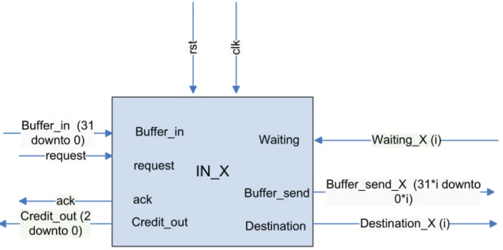
In figure 3.3 the signals which are on the left hand side of the input component build the interface with the previous router or resource. Signals which are on the right hand side belong to the interface with the output component of the same router. Signals “request”, “ack” and “Credit_out” perform the communication protocol based in a handshaking protocol, which is explained in section 3.2.2. Through the signal “Buffer_in” the flits are sent from the previous router or resource to the input component of the next router.
IN_X ack c lk Buffer_in (31 downto 0) request
Buffer_send_X (31*i downto 0*i) Waiting_X (i) Destination_X (i) Credit_out (2 downto 0) rs t Buffer_in request Credit_out Waiting Buffer_send Destination ack
Figure 3.3: Block diagram of the input component.
This component has an input buffer where the flits coming from “Buffer_in” are stored waiting for being routed and sent to the next node in the network. This buffer has capacity for three flits of 32 bits. When the flit is received, the next destination and thus the appropriate output, is found applying the XY routing algorithm, and the signal “Destination_X” contains the number of the output that has to be in charge of sending the flit, as can be seen in table 3.2. This signal is sent to the output and the output has to acknowledge sending back a positive answer through the signal “Waiting”. The input component waits until this positive answer to send the flit through the signal “Buffer_send”. How the output component determines when it is ready to receive a new flit from an input will be explained in section 3.2.1.2.
Decission Signal Destination Destination
x<My_x 00010 West x>My_x 00100 East y<My_y 01000 South y>My_y 10000 North else (x=My_x & y=My_y) 00001 Resource
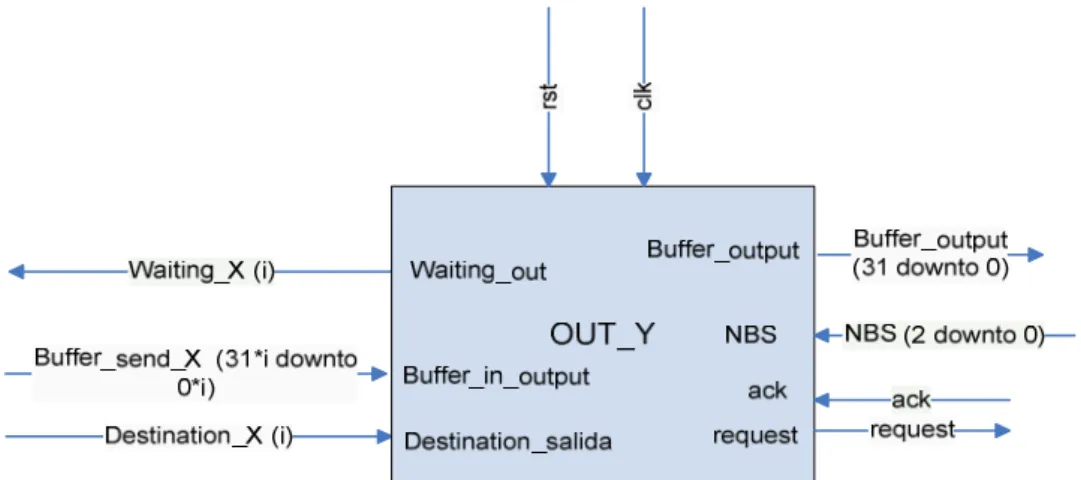
Table 2.2: XY routing results. 3.2.1.2 Output Component
The output component will perform the following functionality:
• Check if neighbouring routers have credit.
• Request handshaking protocol to those neighbouring routers to
which it intends to send a packet.
• Send flits.
• In case of congestion store flits in the output buffer. • Manage the output buffer
• Implement a round-robin policy to select which of the inputs
attempting to use the output will be serviced.
• Lock it services to a certain output when the first flit of a packet
arrives and until the whole packet is sent (wormhole).
• Send a waiting signal to an input sending a packet if no more flits
can be outputted.
In figure 3.4 the signals which are on the left hand side of the output component build the interface with the input components, and signals which are on the right hand side are part of the interface with the next router or resource. As explained in the previous chapter, the signal “Waiting_X” sends an acknowledge whenever the input can send flits to the output, taking into consideration that this destination has to be previously requested by the input through the signal “Destination_X”. If the output is already locked by some other input, there will be no acknowledge from this output and the input will have to wait until the output is unlocked and according to the priority policy there is no other input with higher priority waiting for the same output.
Hardware Router
Figure 3.4: Block diagram of the output component.
Regarding the signals of the right hand side, they perform the handshaking protocol with the next node of the network. “Request” and “ack” perform the handshaking protocol and “NBS” receives the credits from the next router, depending on the space left in the buffer.
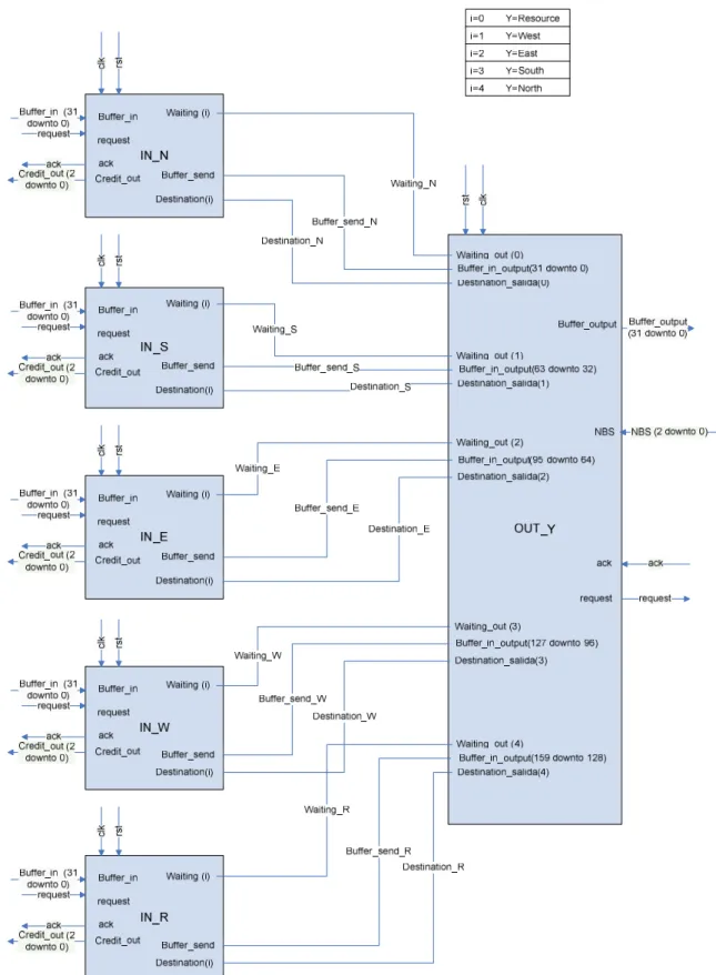
3.2.1.3 Assembled Hardware Router
As it has been mentioned before, the complete router is the result of linking five input components with five output components. In figure 3.5, the router interface towards neighbouring routers is shown.
Hardware Router
The way in which inputs are connected to outputs is described in figure 3.6. In this figure the connection is done with just one output, as the connections are analogous for all the different output components. The box in the upper right corner shows the pairs of (i , Y) values that are possible, being i the bit number of some of the signals and Y the output component placement in the router.
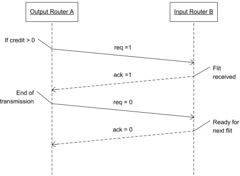
3.2.2 Handshaking Protocol
The protocol that will be used to ensure flit reception for the HW Router is very simple. It just consists of starting a handshaking protocol but just when the output of the sending router knows that the receiving router will have space in its buffer for the flit to be sent. This can be done by checking that the credit signal which is sent by the receiving input is larger than zero.
Once the protocol has started, as it is also shown in figure 3.7, the request signal will be set to one by the output, which will wait for the acknowledgement signal is set to one prior to removing the flit to be sent, which will be done along with setting the request signal to zero. When the input detects that the request signal has been set to zero it will set the acknowledgement signal also to zero and will wait for the next request signal to be sent.
Output Router A Input Router B
req =1 ack =1 req = 0 ack = 0 If credit > 0 End of transmission Flit received Ready for next flit
The handshaking protocol, though very simple, is a time consuming section of the hardware router. It contributes to ensuring that no packet loss is produced in the network as packet drop is not required. Packets are not sent if the receiving router is not ready to receive them and are outputted until the receiving router acknowledges the reception. This feature is not very important in situations where all routers and resources in the network are completely synchronous, but in most of the situations the resources will not be synchronous with their neighbouring router.
3.2.3 Packet Format
The format that the information will take in the NoC has been defined. Each packet containing data will be divided into 10 flits, but there will also be one-flit packets for control purposes.
A flit will be formed by 32 bits with the format shown in figure 3.8.
Time of flit generation origin nr y x T
31 13 12 10 9 6 5 4 3 2 1 0
Figure 3.8: flit format
The header of the flit contains the most relevant data for routing purposes. It comprises bits 0 to 5 and is composed of the following elements:
• Flit type (0 to 1)
There are four different types of flits each of them coded with two bits, table 3.3 presents a summary of such codification. If no packet is being received the flit to be processed would be idle. Control packets consisting of a single flit are called Full Packets (FP). A packet containing more than one flit will start by a Body Flit (BDY) and will present such flits until the last flit of the packet, which will be signalled as End of Packet (EP).
Bit code Type (T) 00 IDLE 01 EP 10 BDY 11 FP
Hardware Router
It is assumed that the hardware router will be part of a NoC with a mesh topology. As four bits have been reserved for the routers’ address, a 4x4 mesh can be considered. The position (x=00, y=00) has been assigned to the bottom left router. The payload of the flit comprises bits 6 to 31. These bits have been assigned different contents for testing purposes. Such contents are:
• Flit number (6 to 9)
In order to verify that all generated flits were received, the flit sequence was numbered. Number 0 was assigned to FP and 10 flits packets were numbered from 1 to 10.
• Origin (10 to 12)
Due to the fact that XY routing is going to be used when testing the router, and as we know the position of the router to be tested and the destination of the packet, the origin of the packets will prove the correctness of the router.
There are five possible origins, the same as inputs. They are coded as shown in table 3.4.
Bit code Origin 000 Resource 001 North 010 South 011 East 100 West
Table 3.4: bit codes for different origins
• Time of flit generation (13 to 31)
In order to be able to estimate the delay of the flit from source to destination (from input to output in our case) it is important to keep track of when the flit was generated. Then it is just required to check at what time the flit was received.
3.3 Hardware Router Testing
In order to test the proper functionality of the design we used Modelsim as a hardware simulator platform. In the first phases of the testing, the stimulus was done by hand in order to see that all the signals within the different components were performing in a good manner and that the overall functionality of each component was right.
When all the components were tested, the system was built and again it was tested with stimulus using Modelsim in order to see if the whole system functionality was achieved or if in the process or merging different components some functionality was lost.
Since producing the stimulus by hand was quite slow and error prone, when some kind of confidence in the system was reached, we used the same test configuration that was used to measure the performance. This configuration is explained in chapter 7. At this point, the performance was not measured, but the correct functionality of the system was checked.
The evaluation of the hardware router performance and a comparison with the other implementation options considered in this Master Thesis are provided in chapter 7.
Router using a GPP
4 Router using a GPP Core
General Purpose Processors (GPP) are an intermediate solution for routers’ implementations. They can not achieve as high performance as ASIC, or Network Processor but to a lesser extent, can do, but the degree of flexibility is even higher than what we can expect from NP. This fact makes GPP very attractive due to the short time to market and the long life of the products, as their functionality can be changed by replacing the software.
One of the goals of this Master Thesis is to explore the different possibilities for router’s implementations. Therefore, a GPP as the main component of a router for a NoC is studied, implemented and tested in order to know the performance that this kind of solutions can achieve.
4.1 GPP Choice: Leon vs Microblaze
The first step is to study the different possibilities of microprocessors available, in order to build the system. When this study was conducted, two major options came up due to the fact that they are configurable, synthesizable and more important, they can be tested using a hardware simulator. These two options were Leon2 processor and Microblaze. There are other possibilities regarding GPPs that could also fit into these requirements, but in this study we restricted the scope to these two processors was a key factor.
Leon2 is a 32-bit RISC processor with architecture compliant with SPARC V8 [12]. It keeps a Harvard style and it is designed for embedded applications. It has many different resources on chip as 16 bits I/O ports, two UARTS, MAC and PCI interface. A complete block diagram can be seen in figure 4.1. Leon-2 VHDL code is available for free under a LGPL license in the website of Gaisler Research [www.gaisler.com].
On the other hand, Microblaze is a 32-bit RISC processor with its own ISA (Instruction Set Architecture) specially designed for Microblaze [13]. The design is optimised for its implementation in Xilinx FPGAs. A complete block diagram can be seen in figure 4.2. Microblaze is distributed with the Xilinx Embedded Development Kit (EDK) which is a netlist of many parameters, but the VHDL code is not available for free as in the case of Leon-2.
Figure 4.1: Block diagram of Leon-2. Taken from [12]
Router using a GPP
I/O ports are a very important processor component for this project, and with Leon-2 processor 16 bits are always available and 32 bits are only possible if the memory bus is configured for 8 or 16-bit operation [12]. This is a main drawback for the project as 5 I/O ports are needed with as many bits as possible and 16 is not a big amount.
In Microblaze, I/O ports are 64 bits width [13], which is a key factor for the design, since it allows 32 bits for output and 32 bits for input, which is the same interface we used for the hardware router design. This was a strong point in the decision of taking Microblaze instead of Leon-2.
Another important factor was the fact that the EDK environment that is provided by Xilinx along with Microblaze, has a very powerful and easy to use graphical interface for modelling the system. This allows a complete system design in a few steps and all drivers needed for all the different parts of the system were automatically generated in C language for the concrete system’s specifications. This advantage was crucial since the time of development using Microblaze was clearly smaller than with Leon-2, where all the code would have to be generated almost from scratch.
Due to these advantages regarding I/O features and development environment the GPP chosen for the simulation of a router system was Microblaze.
4.2 Router Design using Microblaze processor
The system was developed using the Xilinx EDK 6.2 tool. Here, the hardware is instantiated using IP blocks that can be connected through signals and buses. The tool provides a wizard in order to create the system specifying the requirements through setting some parameters in a few steps. This wizard is included in the Xilinx Platform Studio, which is the graphical interface on top of the EDK. In this wizard, it is possible to specify if it is to be used a Microblaze processor or a PowerPC processor, which is also available under the same EDK. Besides that, it is possible to specify the FPGA in which the system is going to be deployed, if needed, the clock frequency, the size and type of memory, cache and different I/O devices.
In figure 4.3 it can be seen the configuration of the system being used, with five bidirectional 64-bit General Purpose I/O ports (GPIO). Each port is composed by 32 input bits and 32 output bits.
Figure 4.3: Block diagram of the system simulated. Modified from [13] All five ports are accessed through the OPB bus and are mapped directly into memory, in such a way that the only thing that it is needed to write or read these ports is the address in memory where they are mapped. This address is given by the XPS and all the drivers in order to manage at a higher level of abstraction these ports are automatically generated as C functions by the tool.
Having five I/O ports allows us to maintain almost the same interface as in the case of the hardware router seen in the previous chapter. This is very important for evaluation and simulation purposes, being the time of development shorter, as the evaluation tool was already built with only some minor changes to be done, and more fair the comparison between the two systems.
Due to the fact that in the case of the hardware router the signals related to the handshaking protocol were not part of the 32 bits of the flits, the packet format needs to be modified in this case as only 32 bits ports are available. The new packet format can be seen in figure 4.4. In this new format the following bits are included:
• The request bit (r) • The acknowledge bit (a)
• The credit bit (c), which indicates if there is any free space in the
input buffer or not.
r a c Time of flit generation nr y x T 3 1 3 0 2 9 28 10 9 6 5 4 3 2 1 0
Router using a GPP
As the time required for the Microblaze to send a packet is much larger than the time required by the hardware router, the time of flit generation has been converted to clock cycles and is not expressed in nanoseconds, as in the case of the hardware design.
The software of the system was developed in C. The other alternatives were assembly language or C++. C was chosen due to its short time of development, level of abstraction and better execution time. With assembly language even though the execution time is faster and the size of code is smaller the time of development would be much higher, due to the fact that the assembly code of the Microblaze and all the instructions would have to be learnt.
Using C++, the time of development most likely would be shorter but the size of the code would be bigger and the execution time would be worse and therefore the performance. Taking into account all these factors, C language seems to be the best option for the purposes of this project.
In order to compile the software written in C, a modified version of GCC is used and a script can make all the models for the simulation. Some other libraries of the hardware are also needed to compile in order to run the hardware simulation. As the aim is to achieve the best performance possible in terms of latency and throughput, the program is written without any function, so that it is not needed to call different functions and to spend time passing parameters and saving the state.
The general architecture of the program is as follows: it is divided in ten parts, one for each input and one for each output, following the idea of distributed intelligence of the hardware router.
For each input, the main tasks that have to be performed are the handshaking with the previous router or resource, the management of the input buffer and allocation of the incoming flits, routing algorithm and request for free output. Since all these tasks, only for one input, may last for about some tens or even hundreds of clock cycles the latency would be very high in case of many inputs receiving incoming flits.
In order to avoid large delays in serving the inputs, all the required tasks mentioned above are interleaved among all the inputs, in such a manner that the handshaking of the first input is followed by the code of the handshaking of the second input and so on until the fifth. The same strategy is followed with the rest of the tasks.
In figure 4.5 there is a description of the main parts of the software. The level of abstraction is quite high in order to make it clear for the reader.
Description of the main parts of the software for the inputs.
Figure 4.5: Description of the main parts of the software for the inputs.
Regarding the outputs, as the tasks to be done are smaller, in terms of lines of code, and can be done much faster it is not needed to split the code and therefore all the code that controls the same output is together and followed by the code of the next output until the fifth one is finished. The description of the code that was developed for handling all the different outputs is shown in figure 4.6.
//the same code for the different inputs is performed if (new incoming flit){
do handshaking(); }
//==================================(repeated five times) If (new flit) {
If(buffer full){
Can not allocate the new flit; Credit=0;
}else{
Allocate new flit;
Change the buffer pointer; }
}
//==================================(repeated five times) If(flit in first position buffer){
If(header flit){
Find destination;
Request output according to destination; Manage buffer; } else{ Send to output; Manage buffer; } }
![Figure 2.2: Architecture of PowerNP. Taken from [7]](https://thumb-eu.123doks.com/thumbv2/5dokorg/5555587.144944/29.892.140.729.430.874/figure-architecture-powernp-taken.webp)

![Figure 3.1: QNoC router architecture, taken from [11]](https://thumb-eu.123doks.com/thumbv2/5dokorg/5555587.144944/34.892.241.657.107.589/figure-qnoc-router-architecture-taken-from.webp)