DESCRIPTION OF FRICTION TEST VEHICLE NO. 5 OF THE
NATIONAL SWEDISH ROAD AND TRAFFIC RESEARCH INSTITUTE
by
O. Nordström and E. Ohlsson
DESCRIPTION OF FRICTION TEST VEHICLE NO. 5 OF THE
NATIONAL SWEDISH ROAD AND TRAFFIC RESEARCH INSTITUTE
by
O. Nordström and E. Ohlsson
D E S C R I P T I O N O F F R I C T I O N TEST V E H I C L E N O . 5 O F T H E N A T I O N A L S W E D I S H R O A D A N D T R A F F I C R E S E A R C H I N S T I T U T E
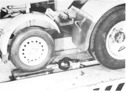
F ig 1 . F r ic tio n test v e h i c l e N o 5 , p h o t o g ra p h ic v i e w from test wheel sid e
The frictio n test v e h i c l e N o 5 of the N a t i o n a l S w e d ish Road and Traffic Research Institute was d e v e lo p e d by the Institute and cam e into use in 1960. H o w e v e r , s in c e then several m o d ific a t io n s h a v e been c a rrie d out on the equ ip m e n t.
B ro a d ly s p e a k in g the m e asuring d e v ic e consists o f a test wheel mounted on a lorry. The test wheel is c o n n e c t e d to the d r i v in g w he e ls of the lorry by means of transmission units. A s the lorry moves forw a rds, the test wheel is forced to operate at a reduced p e rip h e r ic a l speed and thus d e v e lo p s a braking fo rc e , w h ic h is measured.
The relative speed reduction is called slip. The friction force between the wheel and the road is connected to the slip of the wheel. As a rule a maximum friction force is obtained at a slip of 15 to 20 per cent.
One of the transmission units mentioned above is a variable V-belt transmission which makes it possible to change continously the gear ratio between the test wheel and the driving wheels of the lorry, corresponding to a test wheel slip range from 0 to 50 per cent. Thus, with this device it is possible to measure the friction force at any percentage slip within the range and to easily determine the percentage slip at which the maximum friction force occurs.
The principle described has basically two distinct advantages. Firstly, test wheel slip is not influenced by test vehicle speed and secondly, owing to the feed back effect, only a fraction of the braking force must be supplied by the engine of the test vehicle. However, if wished the test wheel may also be locked completely and in this case the total braking force must be supplied by the engine.
Detailed descriptions of the mechanical and electrical measuring equipment of the test vehicle as well as of the calibration of the measuring system are given in what follows.
Description of Mechanical Equipment of the Test Vehicle (Fig 1, fig 2 and fig 3) The friction measuring device is mounted on a Volvo L 430 lorry, which has a 120 hp petrol engine. Total weight of the lorry is 7.500 kg. Maximum speed during measure ment is about 80 km/h.
The mechanical equipment of the test vehicle consists of the following six main groups:
1) test wheel with suspension device,
2) transmission devices,
3) brake (for locked wheel only),
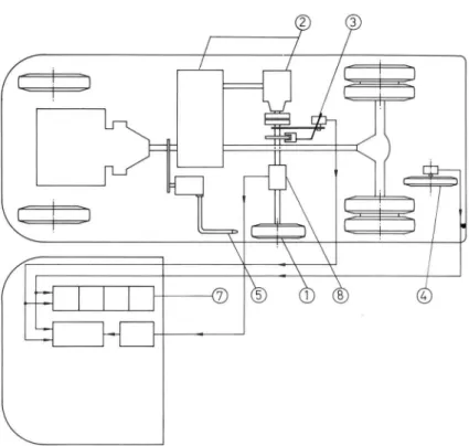
Fig 2.' Friqtion test vehicle No 5, diagrammatic arrangement of the equipment.
Fig 3. Friction test vehicle No 5, perspective drawing.
Legend to fig 2 and fig 3: 1=test wheel, 2=transmission units, 3=disc brake, 4=datum wheel, 5=water nozzle, 6=control system actuators, 7=instrument panels, 8=torque transducer
5) watering system,
6) control system.
The main groups are described at some length below.
1) Test Wheel_,_etc.
The test wheel is carried by a trailing link and is located beside the frame, between the front axle and the rear axle of the lorry. According to occasional demands it can be equipped with test tyres on 14 and 15 " rims and tyre section widths from 5,90 to 7,5 0".
Separate weights used for loading the test wheel are fitted on a lever parallel to and above the trailing link. The load is transmitted to the test wheel by a coil-spring between the weight lever and the test wheel trailing link. The spring movement is damped by a hydraulic shock absorber. By varying the number of weights wheel load can be changed from 120 kp to 500 kp.
Near the test wheel, a vibration absorber is attached to the trailing link. This is a dynamic vibration absorber, which consists of a spring-suspended piston in a cylinder. The natural frequency of the piston combined with the spring is equal to the natural frequency of the test wheel. Thus, the vibrations of the wheel are damped.
AM movable joints in the wheel suspension unit, - except the ends of the hydraulic shock absorber - are fitted with ball bearings in order to diminish the influence of wheel load hysteresis.
2) T|^nsmission_
The test wheel is connected to the driving wheels of the lorry be means of a number of transmission units. One of them is a variable V-belt transmission,which makes it possible to change continuously the gear ratio between the test v/heei and the driving wheels. The slip of the test wheel can be varied from 0 to 50 per cent.
The engine power necessary for driving the test vehicle is reduced by connecting the test wheel to the driving wheels instead of braking it with a conventional brake equipment - in which brake power is converted into heat. Consequently, a constant speed is also easily maintained in braking at high speeds on high friction surfaces.
3) Brake_
A Dunlop disc brake with double calipers is fitted in the shafting of the test wheel. This brake makes it possible to lock the test wheel. When the disc brake is to be used, the test wheel is disconnected from the driving wheels by a multiple disc clutch.
4) Datum_Wh^eel_,_etc_
In order to get accurate measurements of the vehicle speed and of the slip of the test wheel, the lorry is equipped with a datum wheel located behind the rear axle. The datum wheel is carried by a trailing link and is pressed down by a spring against the road. As the datum wheel has to overcome only small resistances, it may be considered to roll practically without slip.
5) Watering System
During friction measurements, the road in front of the test wheel is watered by a watering 3
system in the test vehicle. This system includes a water tank of 1,7 m capacity, a water pump, and a nozzle. The pump is driven by a power take-off in the transmission of the test wheel. The water film on the road has a mean thickness of about 0.3 mm and is relatively independent of vehicle speed.
6) Control System
Some of the movable parts of the test vehicle are operated by means of a hydraulic control system. Pressure oil for this system is obtained from a pump driven by the engine of the lorry. A number of control valves in the cab distribute the pressure oil to hydraulic cylinders. Thus, the test wheel and the datum wheel can be raised and lowered, the variable transmission can be adjusted, and the disc dutch in the transmission of the test wheel as well as the water pump can be engaged or disengaged.
V T I. R a p p o rt 2
POWER SUPPLY EQUIPMENT
BATTERY 12 VDC CONVERTER - ALTER NATOR 220 VAC RECTIFIER EN G IN E ► SHAFT
BRAKE PROGRAMMER EQUIPMENT
PULSES FROM DATUM WHEEL
AUTOMATIC BRAKE PROGRAMMER
MAGNET VALVE
PRESSURE OIL
MEASURING AND RECORDING EQUIPMENT
z
o - n _ Cl —r O: 3G = FLOW METER TRANSDUCER T = TACHOMETER GENERATOR DATUM WHEEL SLIP INDICATOR 100 PILOT LAMPS 7)>,...7\ K = LIMIT SWITCH MAX UP UP K K K K MIN VARIABLE TRANSMISSION DOWN TEST WHEEL DOWN FREE SLIP DATUM WHEEL CLUTCH
~T)
Q
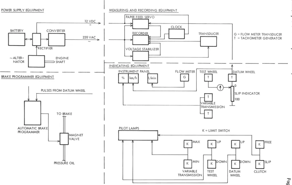
(Q <DFig 4. Blockdiagram of electrical instrumentation.
O & O hi si oh , E: D e sc rip tio n o f
Description of Electrical Equipment of the Test Vehicle (Fig 2, fig 3 and fig 4)
The electrical equipment of the test vehicle consists of the following five main groups:
1) power supply equipment,
2) measuring equipment,
3) recording instruments,
4) indicating instruments,
5) brake programmer equipment.
A description of the main groups and of the units entering into these groups is given in what follows.
1) Power _S_u££j_y_§3,4[pm L
The electrical equipment of the test vehicle requires for its operation both a voltage of 12 V .Ö .C . and a voltage of 220 V . A . C . , 50 Hz.
A three-phase alternator driven by the engine of the lorry is used to supply current. The alternator has a power output of 1 kW. The A .C . voltage is rectified by a selenium rectifier, and the rectified voltage is fed to a voltage regulator. From this regulator a voltage of
12 V . D . C . is delivered to the electrical equipment.
The alternating voltage necessary for a part of the electrical equipment is obtained from a static transistor converter, which has a power output of 100 V A . The converter is equipped with manual frequency control. An adjustable transformer is used to obtain correct voltage.
2) Measu rjngLj^SujgmerrS"
The friction force between the test wheel and the road is converted to an electrical quantity by a transducer in the shafting of the test wheel. This transducer is a Westland Aircraft Ltd torque transducer, type 2, mark 4. The transducer has a normal measuring range of 0-140 kpm, but it can be overloaded up to 280 kpm. Max total error due to linearity and hyste resis - 0 , 1 2 % F .S.D .
The transducer utilises a network of bonded foil strain gauges as the torsion sensing element. The gauges are cemented to a high tensile torsion shaft.
The gauges are connected in a full bridge circuit in such a way that an electrical bridge unbalance is created by torsional strain. The arrangement is such that the shaft strains due to bending, thrust and temperature are self-cancelling and do not contribute to the electrical output. Connection between the stator and the gauges on the shaft is effected by a system of slip rings. The measuring bridge is fed by a stabilized voltage of 18 V . D . C .
3) Recordng_!mtruments
The signal from the transducer is carried to a single channel Mosley potentiometric recorder H 56-680 M . Paper feed of this recorder is modified to be governed by test vehicle speed, so the length of the record strip is directly proportional to the distance travelled. The datum wheel is equipped with a tachometer generator and the voltage from this generator is used as a reference in a servo system governing paper feed. The gear ratio between the servo-motor and the paper feed drum can be varied in 8 steps. The recorder has 10
measuring ranges from 6 m V to 120 V and includes also a channel for time pulses.
The equipment also includes an optinal recorder, Control Instrument potentiometric recorder, 1000, to facilitate recording of special signals as test wheel revolutions, datum wheel
revolutions, event markings etc. A Mosley xy-recorder 135A/Vt may be connected when coefficient of friction as a function of slip is to be studied.
^
iHS:LcajjngJ ns trur^entsThe test wheel and - as mentioned previously - the datum wheel are equipped with tachometer generators. The voltage output of these generators is carried to a potentiometric bridge by means of which the quotient between the two voltages and thus the slip of the test wheel is represented. Calibration of the bridge is carried out with the test wheel rolling freely. The voltage of the tachometer generator of the datum wheel is also carried to a moving coil instrument, which shows the driving speed in km/h.
Each of the two shafts of the variable transmission is also equipped with a tachometer generator. The voltages of these generators are carried to another crossed coil instrument graduated in per cent from ”25 to +25.
A flow meter transducer is mounted in the pipe of the watering nozzle. The voltage of this transducer is carried to an instrument graduated from 0 to 100 l/min. This instrument indicates the magnitude of the water flow.
A number of Iimit-switches are mounted at the different movable, mechanical parts.
These switches actuate some pilot lamps, which show the positions of the above-mentioned parts to the operator.
5) Brake Programmer Equipment
The test wheel can be locked manually as well as by the aid of an automatic brake programmer. This programmer facilitates the work of the operator, and also improves the reproducibility of repeated tests at the same place. The distance over which the test
wheel is locked (10 to 120 m at intervals of 10 m) and the distance between two consecutive lockings (10 to 20 m at intervals of 10 m) as well as the number of lockings are present on the brake programmer. A set of breaker points on the datum wheel governs the programmer, which transmits a voltage of 12 V .D .C . to a three-way magnet valve, and the oil supply to the braking system is regulated by this valve.
Calibration of the Test Vehicle and Determination of the Wheel Load
The friction measuring equipment of the test vehicle is calibrated by two somewhat different methods:
1) calibration in the laboratory,
2) calibration in the field.
Both these methods give the correlation between the tangential force acting on the test wheel and the reading of the chart paper.
Fig 5. Test vehicle No 5. Calibration in the Laboratory.
Fig 6. Test vehicle No 5. Calibration in the field.
Fig 7. Test vehicle No 5. Determination of load on the test wheel.
1) Ca_[ibration_ in the_Laboratory (Fig 5)
The calibration equipment consists of a horisontally arranged, movable platform. The test vehicle is placed on this platform and is locked to it. The test wheel rests on a separate small platform supported by steel-balls. The smaii piatform with its ball bearing rests on a precision weighing-machine and is horizontally anchored to the frame of the equipment by a circular spring dynamometer and a long link. By means of a jack the movable piatform and thus the test vehicle are pushed. This movement rises a friction force acting on the test wheel. The friction force is directly transmitted to and measured by the spring dynamometer. The dynamometer reading divided by the reading of the weighing-machine is then to be co-ordinated with the simultaneous test vehicle record. By increasing the force from the jack by suitable steps a complete set of calibration data is obtained.
2) Calibration in the Field (Fig 6)
The test wheel is dismounted, and a lever (I) is mounted on the wheel hub. A dynamo meter device (2, 3, 4 and 5) is hooked up to the free end of the lever. A torque about the wheel axis is applied by tightening the screw (4). This torque affects the torque transducer. The magnitude of the torque is known when the length of the lever and the force acting on the dynamometer are known. Just as in the case of the calibration in the laboratory, a correlation is obtained here between the torque about the axis of the test wheel and the reading on the chart paper by changing the torque step by step at the same time as the reading of the recorder is registered. When the rolling radius has been measured the torque is converted into tangential force.
3) De^ennin_alJon_q_f Load_on_ theJ est_Whee| (Fig 7)
A lever (1) is mounted on the trailing link (2) of the test wheel. The same dynamometer device as that used for calibration in the field is hooked up to the free end of the lever. By tightening the screw (3), the trailing link is adjusted to the same position as in friction measurements. The load on the dynamometer is read off, and is converted into load on the test wheel.