Problems regarding the design and
execution of free form concrete structures
according to Eurocodes
Bachelor Thesis in the Erasmus Programme
MURRAY. J AND TWYMAN. W
Department of Civil and Environmental Engineering
Structural Engineering
CHALMERS UNIVERSITY OF TECHNOLOGY Göteborg, Sweden 2013
BACHELOR’S THESIS 2013:56
Problems regarding the design and execution of free
form concrete structures according to Eurocodes
Bachelor Thesis in the Erasmus Programme MURRAY. J AND TWYMAN. W
Department of Civil and Environmental Engineering
Structural Engineering
CHALMERS UNIVERSITY OF TECHNOLOGY Göteborg, Sweden 2013
Problems regarding the design and execution of free form concrete structures according to Eurocodes
Bachelor Thesis in the Erasmus Programme
MURRAY. J AND TWYMAN. W
© MURRAY. J AND TWYMAN. W 2013
Examensarbete / Institutionen för bygg- och miljöteknik, Chalmers tekniska högskola2013:05
Department of Civil and Environmental Engineering Structural Engineering
Chalmers University of Technology SE-412 96 Göteborg
Sweden
Telephone: + 46 (0)31-772 1000
Cover:
Cover picture available from: http://www.theconstructionindex.co.uk/news/view/top-10-uk-concrete-contractors--results-and-analysis
Problems regarding the design and execution of free form concrete structures according to Eurocodes.
Bacheler Thesis in the Erasmus Programme MURRAY. J & TWYMAN. W
Department of Civil and Environmental Engineering Structural Engineering
Chalmers University of Technology
ABSTRACT
This paper presents findings related to the research into the design of free form concrete structures. The primary goal of the research is to create suitable design codes for new types of reinforcement, self-compacting concrete and formwork. Research papers focusing on these areas have been collated and analysed, resulting in some interesting findings which may be of use to the academic researchers. It was found that the current codes for steel reinforced concrete structures do not aid design with fibre reinforcement, so suggestions have been discovered as to how a new or adapted set of codes can be developed. The findings from the study of self-compacting concrete have shown that the application of existing codes for regular concrete related to the behaviour of self-compacting concrete. The formwork area of research considered factors such as lateral pressure in the design of geometrically complex formworks and possible solutions have been discovered.
1
Contents
1 CONTENTS III 1. INTRODUCTION 2 1.1 Objectives 2 1.2 Goals 2 1.3 Scientific Approach 22 MAJOR CONCEPTS FOR CONSTRUCTION OF FREE FORM CONCRETE
STRUCTURES 4 2.1 Fibre reinforcement 4 2.2 Self-compacting concrete 5 2.3 Formwork 6 2.4 Existing Findings 7 2.4.1 Reinforcement 8 2.4.2 Self-Compacting Concrete 8 2.4.3 Formwork 9
3 LITERATURE STUDY FINDINGS 11
3.1 Reinforcement 11
3.1.1 Crack Width 11
3.1.2 Failure mechanism and safety factors 12
3.1.2 Bending Moments 15
3.1.3 High Performance and choice of fibres 16
3.1.4 Modelling 18
3.1.5 Use with Self-Compacting concrete 19
3.1.6 Ductility 22
3.2 Self-compacting concrete 23
3.2.1 Aggregate characteristics effect on rheology 24 3.2.2 Relating aggregate findings to rheological behaviour of SCC 25 3.2.3 Thixotropy and an alternative method for determining SCC properties
27
3.2.4 Applicability of current concrete codes for SCC mixes 28
3.3 Formwork 30
3.3.1 Formwork pressure 30
3.3.2 Lateral pressure in geometrically complex formworks 31
3.3.3 Implementation of Complex Formworks 33
4 CONCLUSIONS AND RECOMMENDATIONS 37
4.1 Reinforcement 37
4.2 Self-compacting concrete 38
Preface
This research project has been carried out by two Erasmus students on exchange in the Department of Civil and Environmental Engineering. The project was sourced by the group working on the Tailorcrete research project, with Rasmus Rempling acting as the project supervisor.
The opportunity to research state-of-the-art structural concepts has expanded the authors’ knowledge of the wider aspects of concrete use and the versatility of its application. Prior to undertaking this project, the experience of the authors was limited to an education of concrete use in a more orthodox form. Thus, this project has broadened the authors’ appreciation for the scope of different technologies that exist within the field of concrete.
The nature of performing a desk study leaves one limited to the findings of previous research. As such new and innovative findings are difficult to uncover as no experimentation or calculations are possible on the part of the author. The authors have however been able to collate an extremely large number of articles which arguably provide a better education of the topic than performing a more specific experimental study.
The authors would like to thank Rasmus Rempling for his continued assistance and support during the execution of this task.
Göteborg May 2013
1. Introduction
This research project will address the need for standards and codes to be updated so as to provide a method to design free form concrete structures. The research has three main constituent parts: reinforcement, self-compacting concrete and formwork.
1.1
Objectives
A literature review will be carried out in order to investigate where potential changes could be made to the Eurocodes to enable the successful design and construction of free form concrete structures.
An overall aim of the study is to identify obstacles and hindrances in the Eurocodes that may disrupt the design of reinforcement, formwork and self-compacting concrete. The aim of the literature study is therefore to review previous publications to identify where applications to amend the Eurocodes have been made and the subsequent success of these applications. The financial consideration must also be assessed as the structural feasibility is not so much in doubt as the cost when production is on a large-scale.
1.2
Goals
- To source, collate and analyse past publications related to amendments of the Eurocodes.
- Formulating a literature study conclusion relating the findings that may be applicable to further academic research.
- Suggesting modifications to the Eurocodes based on the literature study to enable the design of free form concrete structures.
1.3
Scientific Approach
The literature study was carried out by sourcing relevant publications regarding amendments to the Eurocodes and information on complex structures. The articles were first compiled in a tablature format, with a summary made and key points listed. Once a sufficient number of articles had been collected and reviewed, the information was grouped into sub-topics and written in an ordered manner in section 3. Once the review was complete, the information was analysed to pick out the most prominent recommendations, which were added to the conclusion in section 4.
The research was conducted by sourcing past publications in order to cross-reference existing information with ongoing research. As such the research was limited to the database of articles that were made available. Each of the three research areas differed in terms of the quantity of information that had been found. In particular, research into fibre reinforcement provided an extensive number of articles into the technology. However, formwork and to a lesser extent self-compacting concrete, was quite limited with regards to relevant information for free form concrete structures. For instance the research into new formwork technologies was limited to only publications from the research group Tailorcrete, as no further external research could be found. On the other hand, the sheer quantity of information on fibre
reinforcement required carefully consideration to achieve a sufficiently broad range of tasks without sacrificing the quality of the research.
2
Major concepts for construction of free form
concrete structures
The work on standardising codes in the project is divided into three major areas: fibre reinforcement, formwork and self-compacting concrete. An overview of each of these areas is provided to explain why they are so important in meeting the needs of the project.
2.1
Fibre reinforcement
The use of fibre reinforced concrete (FRC) has increased hugely in recent times due to the realisation of its high potential and effectiveness in modern structural design (Walvaren, 2009). One of the primary reasons FRC has come to the fore is the great need to structurally upgrade deteriorated and substandard infrastructure. Railways and bridges are being subjected to increasingly heavy loading with the need to transport larger amounts of freight and passengers, though frequently they have been largely unchanged for over fifty years and have been constructed with outdated and substandard materials. FRC, often in only small quantities, can be used to strengthen such infrastructure, removing the need to demolish and re-build (Halliwell, 2004).
FRC technology is also allowing for increasingly complex concrete structures to be designed. In structures that have a high degree of structural redundancy and high stress distribution capacity, it can mechanically beneficial and cost-effective to use FRC as a direct substitute or in addition to traditional steel reinforcement (Di Prisco et al, 2009).
Fibre reinforcement is not intended to be viewed as an alternative to steel reinforcement, but as either a complementary reinforcing element or a replacement when ordinary steel is not deemed effective enough (Beddar, 2004). When used for strengthening, fibre reinforcement consists of fibrous reinforcement held in a polymer matrix to form plates, rods or tubes. The fibres are generally carbon, aramid or glass, which are added in different quantities depending on the physical properties required from the concrete. The fibres are resistant to fatigue and creep and are also durable, having good fire resistance (Halliwell, 2004).
FRC can be used to provide structures with enhanced post-cracking tensile residual strength, or toughness, due to the ability of the fibres to bridge the crack surfaces (Di Prisco, 2009). There are many advantages to using fibre reinforced plates rather than traditional steel plates when revamping a concrete structure. Their low weight allows easier handling and application, whilst also reducing the additional dead load added to the structure. The material also has a higher tensile strength and is non-corroding, so requires less maintenance. The success of fibre reinforced plates greatly depends on the quality of the bond between them and the structure itself (Halliwell, 2004).
FRP reinforced concrete has a much lower stiffness and higher strength than traditional steel reinforcement, which is why it is such a desirable composite material to be used as reinforcement. When a balanced section is considered for FRP reinforced concrete, as shown in Figure 1, it is easier to visualise its differing material characteristics, as the neutral axis is far closer to the compressive end than a balanced section for steel reinforcement would be. Thus more of the concrete section is subjected to tensile stresses and there is a greater strain gradient in the compressive
zone, so larger deflections and less shear strength are expected for shear reinforcement. (Pilakoutas et al, 2012).
Figure. 1: FRP reinforced concrete balanced section (Pilakoutas et al, 2012) Though the benefits of using fibre reinforcement in concrete are now well known, there is still uncertainty regarding how design codes should be adapted to allow for it to be used most effectively and on a wider scale. Much design is carried out using modifications of existing steel reinforced concrete (SRC) codes for FRC structures, mainly using the limit state design approach. The use of steel reinforcement codes when designing for fibre reinforced structures has resulted in overly conservative design safety factors or reduced structural reliability (Pilakoutas et al, 2002). As such, it has become clear that the design codes for fibre reinforcement need to be re-assessed.
2.2
Self-compacting concrete
Concrete is the most extensively consumed man-made product in the world. The use of concrete is now double the total of steel, wood, plastic and aluminium combined (Cement Trust, 2011). As such, constant research and development is undertaken in order to refine the mix of its constituents to achieve the optimum characteristics for a specific purpose, most commonly concerning durability, environmental and economic issues.
The appeal of concrete is clear. The raw materials required are well spread across the world, the cost of the raw materials is low and the properties of hardened concrete lend itself well to large-scale applications. The key decision concerning the certain mix of a concrete is the level of workability in the un-hardened state against the strength and durability in the hardened state. The development of additives, plasticisers and super-plasticisers has helped to avert the negative effect on durability and strength that increasing the water content has (Bob et al, 2010). In addition the process of casting is labour-intensive as compacting is required through the use of a vibrating poker. In the 1980’s, the development of a new type of concrete, named self-compacting concrete, began that would go a long way to solve these problems that had previously been inherent in concrete production (Bob et al, 2010).
Concrete relies on being fully compacted. Insufficient compaction dramatically reduces the mechanical properties of such a structure (Sood et al, 2009). Self-compacting concrete behaves in such a way that eliminates the need for a skilful compacting workforce, thus reducing the variability in the ultimate strength of a concrete structure. It differs to regular concrete due to the systematic optimisation of the constituents and the subsequent composition of these. The result is a concrete that flows to a uniform level, filling all voids within a formwork solely under the influence of gravity, neglecting the need for external compaction methods. The typical constituent mix required to achieve this can be seen in Figure 2 seen below (Bob et al, 2010):
Figure. 2: Typical constituents of SCC compared to ordinary, vibrated concrete Typical filler materials used are limestone powder, quartzite powder and recycling industrial waste. The significant differences between the two mixes arise from the higher proportion of ultra-fine materials and chemical admixtures used in self-compacting concrete. Typical ways in which self-compacting concrete is tested is through slump-flow, L-box and V-funnel tests. These have now been implemented into recommendations and manual written in the past decade showing that self-compacting concrete is deemed a positive forward step in the development of concrete structures (Bob et al, 2010).
2.3
Formwork
Formwork plays a key role in the construction of cast in-situ concrete structures. The design of formwork is often as crucial as the design of the structure itself due to the considerable loss of time and finance in correcting a mistake during construction. Therefore the determination of lateral pressures on the formwork is critical to the design.
The necessary lateral formwork pressure depends on the following five parameters: the density of the concrete, the formwork dimensions, the pouring rate of the concrete, the temperature and the type of binder (Perrot et al, 2009).
The concrete must be poured at a quick enough rate to ensure the entire cast structure builds up a lateral pressure against the formwork. If the concrete is not cast quickly enough then it can build up an internal structure and has the ability to
withstand the vertical forces exerted by the concrete being cast above it without increasing the lateral stress on the formwork (Perrot et al, 2009). The lateral pressure exerted on the formwork can be seen in the Figure 3 below.
Figure. 3: Formwork pressure profile, Kim et al, (2011)
The lateral pressure up to d1 increases linearly correlated to the head at that
point. The rate of increase of lateral pressure then decreases up until d2 as the cast
concrete begins to stiffen due to thixotropy. The depth d2 represents the point whereby
lateral stress is at a maximum. The effect of hardening then begins to reduce the lateral pressure exerted onto the formwork. The formwork design should therefore correspond to σmax (Kim et al, 2011).
Concrete behaves as a fluid with a yield stress during casting. This is dictated by the density, the pouring rate, the temperature and the type of binder of the concrete. The yield stress is the minimum stress required for flow to occur, in this case most commonly exhibited by gravity. Yield stress, associated with viscosity, is the primary factor in dictating whether the concrete will fill the formwork shape.
Gravity produces a pressure gradient within a fluid concrete structure. If this pressure gradient exceeds the inherent yield strength then the concrete will level out. The viscosity will dictate the rate at which it does level out. By testing a concrete sample for yield stress we can predict if it will fill the required formwork. This testing is most appropriate on site as concrete samples are often known to experience an increase in yield stress during transportation to site, thus decreasing workability (Roussel, 2009).
In relation to self-compacting concrete, formwork specifications are required to alter. The properties of self-compacting concrete are worked to improve the passing abilities of concrete without segregation. This increased workability increases the lateral pressure exerted onto the formwork. The safety and cost of the formwork when using self-compacting concrete therefore become an issue. The subsequent design procedure is founded on hydrostatic pressure which although safe is uneconomical and excessively conservative (Kim et al).
2.4
Existing Findings
Much work has already been carried out by the research group TailorCrete in meeting the requirements to design free form concrete structures. This information is outlined so as to provide a platform from which further research will be carried out.
2.4.1 Reinforcement
The main reinforcement work was carried out by Chalmers University of Technology, with thorough analysis of possible reinforcement solutions being carried out. The main focus of the work has been to find the pros and cons for creating complex shapes using automated processes for the suggested reinforcement solutions. The findings concluded that traditional reinforcement should not be excluded and that combining it with other reinforcement materials, such as glass fibres, polymer fibres and textile reinforcement are realistic solutions (TailorCrete, 2011).
Linear finite element analysis was used to analyse two example free from structures, a reinforcement cage with complicated geometry and reinforcement for a double curved wall. The analysis was compared to the FIB Model Code 2010 to see how well the code predicted the performance of the structures when steel fibres were used in the concrete. It was found that the codes underestimate the capacity of the structure and this becomes increasingly significant as more fibres are added to the model (TailorCrete, 2011).
The main areas which need to be addressed before fibre reinforcement can be used as an effective material in designing structures are outlined:
Recommendations for design process with finite element analysis are lacking for structures with fibres and fibre/traditional combinations.
Shells with fibre reinforced concrete are sparsely covered with regard to verification of safety and serviceability.
Structural concrete members such as continuous beams of fibre reinforced concrete need to satisfy ductility requirements. However, there is no method proposed.
The methods for calculating the deflection of fibre reinforced concrete structures need some clarifications.
The material response of high and ultra-high strength concrete is not covered in the recommendations for fibre and fibre/traditional reinforcement (TailorCrete, 2011).
2.4.2 Self-Compacting Concrete
The Danish Technological Institute has been responsible for research into self-compacting concrete (SCC). Their work focuses on the effect of material properties, casting techniques and boundary conditions on the quality when SCC is used, so as to determine whether it can be used in more complex structures than currently possible (TailorCrete, 2011).
There are three main topics which have been highlighted as the most crucial in developing codes for SCC usage:
Specifications for theological properties: Rheology is considered the most appropriate way of classifying types of SCC, but different types of reinforcement within the concrete mean that different limitations need to be set due to increased risk of blocking and demands for filling ability.
Maximum aggregate size: Complex free form concrete structures may potentially effect the maximum aggregate size possible in SCC, so guidelines must be created for this.
Pumpable fibre SCC: Using fibre reinforced SCC affects the ability of the concrete to be pumped, as the fibres themselves affect the rheology of the concrete. Therefore guidelines must be created to relate pump diameter, pump length, fibre type and rheology (TailorCrete, 2011).
Their work will be focused on testing of up to 750 litres of SCC with different rheological properties. The aim is to find a suitable model to predict the rheological performance of the SCC based on mix composition (TailorCrete, 2011).
2.4.3 Formwork
The Danish Technological Institute is also responsible for formwork. Their main focus has been to select and modify formwork materials that can be processed using automated or semi-automated systems and robot technology, providing new design possibilities for free form concrete structures. There is also research into finding suitable release agents and coatings that will allow such formwork to be reusable (TailorCrete, 2011).
There are three main formwork types that are being investigated: Milled formwork, Moulding formwork and Triangular formwork. For each of these formwork types, there are four main considerations:
Geometric conditions: The allowable geometric production limits for structural elements challenge the precision of formwork created.
Surfaces: There are specifications for the resulting appearance of both visible and non-visible concrete, which need to be met by the formwork used.
Formwork pressure: Using SCC may lead to very high pressures being put on the formwork, thus deformation of the formwork may be more prominent.
Choice of material and system: New formwork types can be used currently when encased by traditional formwork which bares the load. New formwork types must be incorporated into the standards and codes to be used alone (TailorCrete, 2011).
Work carried out so far on wax formwork has revealed that, though it is a waste-free method of creating non-repetitive concrete structures, it is a labour intensive process (TailorCrete, 2011).
Milled formwork creates parts coated with a flexible and reusable rubber skin, making it possible to reuse the formwork without waste. The work on milled formwork incorporates the load distribution layer, which is a stacking system developed in TailorCrete. The rubber skin helps achieve a smooth surface, better release between the concrete and formwork and allowing the formwork to be reused (TailorCrete, 2011).
The three formwork types investigated have been compared against different curvatures of surface being designed, with all three being more cost effective than the reference system used in comparison. It has been found that multi-edge formwork is the most cost-effective when low and medium curvatures are used. Wax formwork is found to use less energy in structures with low and high curvatures. Milled formwork
is found to be the most usable, thus is the best to use in structures with low, medium and high curvatures and surface detailing. It is found that all three formwork systems provide good surface quality and that the edges and joints provide good results (TailorCrete, 2011).
3
Literature Study findings
Findings from the review of research papers focusing on the three constituent parts of the research are presented: reinforcement, self-compacting concrete and formwork. Relevant diagrams and equations have been included in the text.
3.1
Reinforcement
The focus of much current research on reinforcement is in the use of different types of fibre-reinforced concrete. There are currently no Eurocodes that deal with designing with fibre-reinforcement, only recommended guidelines which have yet to be verified as correct and safe ways to design with the material. This section of the report will focus on the key areas outlined in section 2.4.1, as well as other useful design suggestions found in relevant publications.
3.1.1 Crack Width
One key consideration for designing FRP reinforced concrete at the serviceability level is the control of crack widths. Cracking in members can compromise the structural function, durability, water-tightness and aesthetic appearance of the building, therefore controls must be in place to predict and thus limit crack widths in members. Equations exist for calculating crack widths in steel reinforced concrete, and the suitability of using these equations for FRP reinforced concrete depends on the bond performance between the reinforcement and the concrete, as the young’s modulus can easily be changed to fit the new material. If the FRP longitudinal reinforcement’s bond performance is equal to or greater than the steel alternative, the crack width can be calculated in this method with good accuracy. However, if the bond performance is significantly higher or lower than that of steel, the crack widths will be underestimated or overestimated respectively (Sonobe et al, 1997).
Current design codes for steel reinforced concrete beams allow a maximum crack width of 0.33mm, however it is suggested this value should be greater when using FRP reinforcement as it is a more ductile material. No official design guidelines have been introduced that address crack width in FRP reinforced concrete beams, however suggestions have been made. One suggestion is to limit the crack width to 0.51mm which is supported by the CHBDC, ACI committee and JSCE. To be successful in limiting crack width to this level, the strain value must be limited to 0.2% in the reinforcing element at serviceability level. This value for strain has been obtained by testing which found the strain at this maximum crack width (Shehata et al, 2000).
An experimental study was carried out by Baena et al, resulting in more information becoming available to support the analysis of crack widths in FRP reinforced concrete beams in tension. Equations to calculate crack width and maximum crack width have been adapted in both ACI and Eurocode 2 to account for differences in bond behaviour between steel and FRP reinforcement. The proposed ACI equations for crack width do not specify coefficients in their equations for FRP reinforcement, and when the experimental data is inputted the equations lead to an underestimation of crack width. However the ACI codes lead to a more accurate prediction of maximum crack width with equation (1) (Baena et al, 2011).
The recommended Eurocode equations for crack width specify a bond coefficient to allow for the different properties of FRP reinforcement, however when this is used there is a great overestimation of crack width. The recommended equations rely heavily on prior calculations of crack spacing, which are also overestimated with the suggested Eurocode equations. However, when the experimental results of crack spacing are used, the suggested Eurocode equations for crack width become valid. The equations considered here are 2-92 (2) and 2-04 (3) which are the two alternatives for calculating characteristic crack width suggested by Eurocode 2 (Baena et al, 2011).
One thing which must be considered when experimenting with crack widths in FRP reinforced concrete members is the distribution of fibres within the member. The dimensions of the specimen being tested and designed for will greatly affect the likelihood of consistent results being observed. In large members undergoing cracking in tension, the distribution of fibres can be considered uniform and thus a safety factor can be easily adopted. However in all other cases, such as in thin walled and high performance structures, the distribution and orientation of fibres will not be so uniform. One suggestion is to use different safety factors when considering local or global behaviour when cracking in SLS and ULS, shown in equations (4) and (5). The factors for local behaviour can be raised so high as to assume no fibres exist when the specimen is particularly thin or bearing a high load. (Di Prisco et al, 2009).
3.1.2 Failure mechanism and safety factors
A significant problem for the creation and adoption of design codes for FRP reinforced concrete is that its failure mode is not the same as for steel reinforced concrete. The design codes in place for steel reinforced concrete are based on the ductile properties of steel, so if used for FRP reinforced concrete it will inevitably result in incorrect sizing of members, leading to either an overly safe design or a dangerously weak structure. FRP reinforced concrete’s failure mode will depend more upon the actual concrete rather than the reinforcement itself, so the principles on which the current codes for steel reinforcement are based upon cannot be applied in the same way (Pilakoutas et al, 2012).
(1)
(2)
(3)
(4)
One of the main purposes of FRP reinforced concrete elements is to strengthen existing structures, which can be achieved by bonding FRP externally to the necessary areas. When these are used, there are two major failure modes which can be encountered, either classical or premature. Classical failure are the types encountered in normal concrete beams or slabs, which can be attributed to either the crushing on concrete in compression or the FRP plates failing in tension. It is suggested that the FRP plates would only fail in tension in very lightly reinforced sections, so concrete crushing is more likely to occur first. Premature failure can occur due to either the FRP plate de-bonding where it is glued on or the concrete cover ripping off. De-bonding is the result of the adhesive being used to keep the plate in place being too weak, which should be a less common problem than the cover ripping off, which is induced by flexural cracks forming at the ends of the strips. This premature failure is most likely to occur when the FRP plate is applied at the bottom of the concrete element, as shown in Figure 4 (Chaallal et al, 1998).
Figure. 4: Concrete cover ripping off from bottom of concrete element (Chaalall et al, 1998)
Flexural failure can occur in FRP reinforced concrete due to either the concrete crushing in compression or the reinforcement rupturing in tension, and this failure mode must be considered when safety factors are adopted. Partial material safety factors or strength reduction factors are used to determine and achieve the desired failure mode, which have been adopted by the early and on-going attempts to create codes for designing structures with FRP reinforced concrete. The Japanese guidelines are based around modifications of steel reinforced concrete codes, as shown in Figure 5. They provide safety factors, however they are not accompanied by information about the failure mode that would result from applying the given safety factors. The current Eurocode design guidelines similarly do not provide any information about the predominant failure mode that would result from applying their suggested codes, though they do include considerations about short and long-term structural behaviour. The proposed American design guidelines do include information regarding failure modes, as they propose the predominant failure mode to be concrete crushing. This proposition results in a minimum amount of reinforcement specified to ensure that this is the failure mode that does occur. (Pilakoutas et al, 2012).
Figure. 5: Japanese guidelines with safety factors presented (Pilakoutas et al, 2012) A simulation was carried out to determine the failure mode of carbon and glass FRP reinforced concrete (CFRP and GFRP) members when different proposed safety factors were applied, the procedure for which is shown in Figure 6. It was assumed that failure would occur due to concrete crushing, however the reinforcement could fracture where a low reinforcement ratio and high compressive strength were present. It was calculated that there is a probability of up to 0.2 and 0.73 for CFRP and GFRP reinforced concrete respectively for failure to occur due to fracture of the reinforcement. These probabilities occur when the designed tensile strain in the reinforcement (Pf) is very close in magnitude to the design limit (Pilakoutas et al,
2012).
Figure. 6: Assessment procedure for failure mode of FRP’s (Pilakoutas et al, 2012) It was also observed that the flexural structural reliability level is not actually affected by the safety factor (
γ
FRP) used, so long as concrete crushing is assumed to bethe mode of failure. It is proposed therefore to discard or use a minimum value of γFRP
in the design process and instead use the uncertainties related to mechanical characteristics of the material. This is important as FRP reinforced concrete is intended to be used in aggressive environments and its long-term characteristics are still unknown, so safety factors must be incorporated to handle this uncertainty over future performance. It is clear that the ratio between the dead and live loading on a structure does affect Pf . Therefore it is more important to use design factors
accounting to different types of structure and loading conditions than for the reinforcement itself, as this ratio is one of the most important parameters in FRP reinforced concrete design. (Pilakoutas et al, 2012).
3.1.2 Bending Moments
The use of FRP reinforcement in strengthening concrete structures brings into question whether the moment distribution capacity is affected. This can be a problem because of the uncertainty regarding the orientation of the fibres within the concrete, which can reduce local ductility. There is a great disparity between the understanding of the behaviour of simply supported and continuous beams strengthened with composite materials such as FRP, the latter being far less developed. This disparity is highlighted by the lack of understanding of how FRP reinforcement affects the moment distribution capacity of continuous beams. It is a particularly crucial property to understand, as in continuous beams the moment distribution provides a safety reserve beyond the elastic range. This safety reserve prevents global failure due to one critical section yielding, so it must be better understood how the presence of FRP reinforcing elements affects the ability of this phenomenon to occur (Coccia et al, 2008).
A simulation was carried out which revealed a negative relationship between the redistribution capacity and thickness of FRP reinforcement plates used in a concrete beam, using equation (6), with the resulting graph shown in Figure 7. This affect is also irrespective of the dimension of the beam, as shown by the same shaped curves for beams A, B and C, which are of different beam thicknesses. However, when the location of the FRP reinforcing plates is analysed, Figure 8 shows that the effect on redistribution capacity is more variable. When placed at the top compression side of a section, the FRP plates remove all redistribution capacity. However when the plates are placed only at the bottom of the section, there is a significant increase in redistribution capacity with increasing plate thickness. Here the plates increase the strength of the mid-span section without changing the rotation capacity at the supports, thus allowing the section to withstand an increasing in bending moment (Coccia et al, 2008).
Figure. 7: Relationship between FRP plate thickness and redistribution capacity for three different beams (Coccia et al, 2008)
Figure. 8: Effect on redistribution capacity when FRP plates applied in different areas of section (Coccia et al, 2008)
3.1.3 High Performance and choice of fibres
There are many obstacles that are preventing fibre reinforced concrete being developed into a high or ultra-high performance (HPFRC or UHPFRC) material. Increasing fibre content resulted in reduced workability in the early stages of development, but when this problem was solved and greater strain capacities and strengths were possible, a problem arose regarding reliability due to the scattered arrangement of fibres within the concrete. However these problems are being solved due to new techniques and the use of superplasticisers, which are allowing strengths of up to 200 N/mm² to be reached, which makes fibre reinforced concrete capable of being defined as HPFRC and UHPFRC. Despite these advances, there are no accepted design recommendations, due to uncertainties about its material properties (Walraven, 2009).
There is a significant difference between the mechanical properties in fibre reinforced concrete when there is a hybrid system used, which is displayed most prominently in HPFRC. In HPFRC, the fibres are much finer and act more as an integral part of the concrete’s mechanical structure, as they are activated instantly as micro-cracking occurs. The correlation between the size, shape and combination of these fibres and the resulting concrete strength must therefore be understood before design codes can be developed. Figure 9 shows how, for a given total quantity of fibres, the mixture between long and short fibres has an impact on the resulting flexural strength. The results confirm that it is optimum to use a combination of fibre sizes. For example, the same flexural strength can be achieved using 3% and 5% fibre content, when at 3% there is a mixture of fibre sizes and at 5% only one type of fibre has been used (Walraven, 2009).
Figure. 9: Flexural strength when different compositions and quantities of fibres are used (Walvaren, 2009)
One drawback of using HPFRC is that fatigue, which is seldom a problem encountered in normal concrete design, can be a problem. Fatigue may occur in structures where repeated cyclic loading occurs, such as bridges, which are one of the primary types of structure that are due to benefit from rehabilitation with fibre reinforced concrete elements. Figure 10 shows the S-N curve for three different mixtures of concrete, with the best performing mixture being the HSFRC, which consists of 1.6% volume of fibres of length 13mm and width 0.16mm (Walraven, 2009).Testing of different concrete mixtures with different volume percentages of fibres reveal a great range in fatigue performance, with a 2% volume fraction of steel fibres shown in Figure 11. It was found that a safe limit for cyclic fatigue loading in bending can be set at 65% of the ultimate strength (Naaman and Hammoud, 1998).
Figure. 10: S-N curve for three different concrete mixtures (Naaman and Hammoud, 1998)
Figure. 11: S-N curve for 2% volume fraction of steel fibres (Naaman and Hammoud, 1998)
3.1.4 Modelling
The suitability of finite-element and other modelling software for fibre reinforced concrete elements has yet to be agreed upon, with no current guidelines existing. The difference in failure mode is a significant problem with modelling, as the rupturing and failure of the FRP elements must be accounted for alongside the customary failure modes in the concrete itself (Abela and Attard, 2011).
One computer program developed for analysing concrete beams retrofitted with FRP wraps is PACCC-FRP (plastic analysis of circular concrete columns). This model is based upon determining the saturation level of FRP based upon a desired ductility value, as above a certain point adding more FRP reinforcement will not increase the strength and ductility of the concrete. The model also accounts for the differing ability of a concrete column to increase its ductility with added FRP, as a concrete column with a more brittle failure mode will experience a greater increase in strength and displacement when retrofitted with FRP’s. The saturation level is called a ductility wrap envelope (DWE), which defines the maximum level and allows for
analysis of increasing ductility below this level. Figure 12 shows this analysis for a sample column, where it can be seen where adding more FRP wraps gives the most significant increase in ductility and at which point the DWE has been reached, which is where the graph levels off. The equations used to determine these values are shown, (7) and (8), for carbon and glass fibre wraps respectively (Abela and Attard, 2011).
Figure. 12: Displacement ductility vs number of FRP wraps up until DWE (Abela and Attard, 2011)
3.1.5 Use with Self-Compacting concrete
Adding fibre reinforcement to self-compacting concrete can extend its already impressive structural capabilities. Fibres can increase the tensile and flexural strength of concrete by bridging cracks and retarding their propagation, thus if used in self-compacting concrete it can widen the possible fields in which it can be used. However fibres can affect the workability of concrete (El-Dieb and Reda, 2011).The workability of self-compacting high performance concrete (SCHPC) is determined by a delicate balance between factors such as superplasticiser dosage and water/binder value, and achieving a desired level of workability requires particular care when fibre reinforcement is used in the concrete. It is therefore important to better understand how adding different types of fibres with different compositions of concrete affects workability. Testing procedures must also be developed to better measure the rheology and workability when different types of fibres are added to SCHPC (Ding et al, 2007).
Figure. 13: Types of fibre used in testing (Ding et al, 2007)
Flow channels are a useful tool to measure the dynamic behaviour of concrete, as parameters can be controlled such as speed and distance of flow so that useful data can be obtained. A test was carried out in a flow channel using four samples of fresh concrete with micro-fibres, as well as ordinary concrete (OC), and observing its dynamic behaviour. Details of the types of fibres used in testing are shown in Figure 13. The results of this test can be seen in Figure 14, which reveal that the combination SFRCF10 (10kg/m³ steel fibre F) and PFRCA1 (1kg/m³ PP-fibre A) maintain the most similar characteristics to OC, thus showing that adding these combinations of micro-fibres does not affect the workability of the concrete. PFRCA2 (2kg/m³ PP-fibre A) and SFRCF30 (30kg/m³ steel PP-fibre A) have poorer results, revealing that adding the same micro-fibres in different quantities can have a huge effect on the workability of the concrete (Ding et al, 2007).
Figure. 14: Comparison between mixtures of concrete with micro-fibres and OC (Ding et al, 2007)
Macro-fibres can also be added to SCHPC, however it is not possible to use flow channels to test the workability of the mixture, as the steel reinforcement will block the flow of the larger fibres. Instead, testing with a J-Ring or L-Box appears is a more appropriate way of modelling the flow of the material. The results from L-box testing different macro-fibres in SCHPC are shown in Figure 15. The two types of
macro-fibres which display the most significant drop in workability, PFRCE7 and PFRCC7, are PP type C and D fibres (Ding et al, 2007).
Figure. 15: Effect of adding macro-fibres to concrete workability (Ding et al, 2007) A useful testing method to monitor the effect of adding fibres to self-compacting concrete is using a filling box, as shown in Figure 16. This evaluation method reveals the filling capacity and passing ability through reinforcement of different mixtures of concrete. The filling capacity is the percentage of space filled by the concrete of the total area in the filling box compartment. The results of adding increasing amounts of fibre content to the concrete mixture can be seen in Figure 17 for three concrete mixtures. The negative relationship shows that adding fibres does reduce the filling capacity, but adding up to between 1000 to 1300gm/m³ of fibres meets the minimum required filling capacity for SCC, as shown by the horizontal line at 90%. (El-Dieb and Reda, 2011).
Figure. 17: Filling capacity for different mixtures of concrete (El-Dieb and Reda, 2011)
3.1.6 Ductility
Ductility is an important requirement when designing concrete, and as such it is necessary to develop guidelines for the required ductility when using fibre reinforced concrete. One advantage of having a ductile structure is that it provides a warning before failure, which is displayed well in steel reinforced structures due to the failure mechanism of the steel reinforcement. Fibre reinforcement behaves in a linear-elastic manner closer to failure than steel, thus will not provide the same warning and will fail in a more brittle manner. It is therefore critical to have procedures to both improve the ductility of fibre reinforced concrete structures and also to be able to better measure it (Wang and Belarbi, 2010).
Due to the differing mechanical characteristics between steel and fibre reinforcement, the traditional definition of and approach to finding ductility must be changed. Two proposed methods of solving this are the Energy-based approach and the Deformation-based approach. One attempt using the Energy-based approach defines a ductility index, which is the ratio of the total energy to the elastic energy, as shown in equation 9. The values for this equation are obtained from a load-deflection curve shown as Figure 18, where total energy is the entire energy underneath the curve and elastic energy is the area underneath the line bounded by the elastic slope line, S. This method relies heavily on being able to select points P1, S1 and S2, though experimentation will not always provide such distinct points (Wang and Belarbi, 2010).
Figure. 18: Load-Deflection curve used in Energy-based approach (Wang and Belarbi, 2010)
The Deformation-based approach is based upon the deformation margin between the concrete’s ultimate and serviceability state. The ductility index is calculated using equation 10, using both strength and a deflection factors, which are attained by equations 11 and 12 respectively. An alternative curvature factor (13) can be used in replacement of the deflection factor, as it can lead to more consistent results. The two methods for calculating the ductility index are quite different, with the Deformation-based approach leading to a more significant difference in ductility when fibre reinforcement is used instead of steel (Wang and Belarbi, 2010).
3.2
Self-compacting concrete
Deliverable 9.1 defines three key aspects of self-compacting concrete that require codes and standards to achieve clarification of the optimum composition of SCC constituents for a given TailorCrete purpose. These aspects are specifications for rheological properties, maximum aggregate size and pump-able fibre SCC. This section of the report will investigate these considerations, along with existing code information, to make recommendations based on the research of the literature study. The pump-able fibre SCC has been included in the fibre-reinforcement section of the empirical literature study findings. Furthermore, information on the maximum size of
(10)
(11) (12)
aggregate due to reinforcement is limited due to the lack of research that has been conducted in this area.
3.2.1 Aggregate characteristics effect on rheology
The properties of a given concrete sample depend heavily on the characteristics of the aggregate used, namely size, gradations, surface texture and the volume of individual grains in relation to the overall volume of the mixture. This is as a result of the inter-particle forces that occur whilst the concrete is in its uncast state arising from the interlocking and frictional forces that the grains impose on each other (Hu et al, 2011).
Yield stress and hence viscosity has been shown to increase as the relative ratio of aggregate to cement increases. This is due to the increase in internal forces between the aggregate grains that hinder movement. Well graded aggregate results in a more tightly packed structure that requires less cement to fill the inherent voids. The size of the aggregate will dictate the amount of cement required as smaller grains will require more water content for a given consistency. The surface structure of the grains will also affect the rheology of the mixture as rough grains that vary in shape will have a higher yield stress than smooth, circular grains (Hu et al, 2011).
Hu et al. state that despite the significant impact that aggregate properties have on concrete rheology, very few aggregate parameters are used in the study of rheology. As such, various methods were tested for characterising coarse aggregate to subsequently investigate the effect that this characterisation has on a sample of concrete (Hu et al, 2011).
The coarse aggregate was sieved and recombined in order to separate the desired samples of aggregate. The void content was calculated by weighing the amount of aggregate that would fill a specific sized container. The shortfall in mass arising from the voids would be an indication of the void content. It was found that angularity increases the void content whereas gradated aggregate resulted in less voids. The increase in voids requires more paste and mortar to achieve the same workability as a mix design with fewer voids (Hu et al, 2011).
The friction angle of a sample of aggregate was also used as an indication of the inherent yield stress of the aggregate. The basic soil mechanics concept of friction angle was used as an indicator for a given sample. Different samples of aggregate were poured onto a flat surface creating a cone-like structure. This was continued until the gradient of the slope became relatively constant. The angle made by the pile of aggregate was then taken as the friction angle. Once again, the ungraded, larger aggregate sample resulted in having the highest friction angle, a further indication that smaller aggregate provides a more workable mix (Hu et al, 2011).
The nature of the rheological properties was then tested using a portable IBB rheometer. Concrete mixes were broken down by an impeller moving in a planetary manner. The results of the experiment, seen below, show concrete to behave similarly to that of the Bingham model of a rigid body at low stresses acting as a viscous fluid at high stresses. This reinforces the credence that concrete can be cast into a pre-formed shape provided the shear stresses resulting from gravity or applied force are greater than the inherent yield stress. Upon testing samples of varying content of coarse aggregate, it was seen that samples with a high CA content had higher yield stresses and viscosity. This is because there was less mortar available to coat
individual particles which provides better flow, resulting from the nullifying of frictional forces (Hu et al, 2011).
Figure. 19: Concrete acting in a manner similar to that of the Bingham model Testing using fine aggregate showed that a high sand content resulted in a lower yield stress and viscosity than a low sand content. This is due to the fact there is less mortar available to coat the fine aggregate particles (Hu et al, 2011).
The summary of the findings show that higher yield stress results from higher volume of CA, ungraded CA, smaller CA and higher FA content. Futhermore, a model is suggested for characterising aggregate through factors such as fineness modulus, uncompacted void content and friction angle (Hu et al, 2011).
3.2.2 Relating aggregate findings to rheological behaviour of SCC
Reinhardt and Wüstholz investigated the effect of changing the constituent composition of SCC on the properties of the resulting fresh concrete. They would model concrete as a two-phase system comprised of the fluid phase paste and the solid phase aggregate. The interaction of these two subsidiary elements would dictate the behaviour of the concrete. The parameters paste volume, mortar volume and coarse aggregate volume can be arranged to acquire a new parameter, excess paste volume. This is said to be a reliable defining factor for workability of an SCC concrete mix. This arises from being able to characterise the results of typical testing methods such as the slump test to describe yield stress and plastic viscosity (Reinhardt and Wüstholz, 2006).Slump tests and V-funnel tests are typically used to observe the flow properties of a concrete mix. They are inexpensive and easy to perform. However, they provide no physical flow parameters. These parameters can be acquired by using viscometers or rheometers but this is often not reasonable on site. Reinhardt and Wüstholz therefore look to create a method for characterising these flow parameters by more simple means: analysis of the concrete’s content in a two-phase model (Reinhardt and Wüstholz, 2006).
Concrete is acknowledged to be a Bingham liquid. This is a liquid that will flow once its residual yield stress has been exceeded. In characterising the properties of a concrete mix two values are required: the yield stress to be exceeded to enable flow and the viscosity dictating the rate at which a liquid will flow to fill a given
space. The excess paste method is designed to relate these parameters to the calculated excess paste (Reinhardt and Wüstholz, 2006).
The model is demonstrated in Figure 20 below followed by the governing equation.
Figure. 20: Excess paste calculation
In this model the constituent parts of the equation are easily calculated. The loose bulk density is calculated using a 101 container. The method idealises the aggregate as spheres. Once the excess paste volume has been determined the thickness of the excess paste can be determined using the following equation.
The parameters in this equation arise by separating the aggregate into several different classes based on size. ni is the number of a certain class of particles
calculated by mass. ri is the radius of that class of aggregate. From this equation a
value for paste thickness can be obtained (Reinhardt and Wüstholz, 2006).
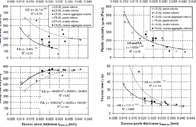
Values for paste thickness can then be analysed against results for yield stress, slump flow, plastic viscosity and V-funnel time. As can be seen from the results in Figure 21, there is a satisfactory correlation between excess paste thickness and the other parameters.
(14)
Figure 21: Relating excess paste thickness to flow properties
The best fit lines can therefore be used to predict the fresh concrete’s properties for a given excess paste thickness. Furthermore a direct relationship can be made between excess paste thickness and the parameter t500, a measure of how long a
concrete mix takes to reach a diameter of 500mm during a slump flow test. It is generally accepted that slump flow depends on yield stress as the concrete deforms under its own weight until it reaches its yield stress (Reinhardt and Wüstholz, 2006).
3.2.3 Thixotropy and an alternative method for determining SCC
properties
Erdem et al devised an alternative method to calculate the rheological properties and thixotropy of SCC using those of concrete-equivalent mortar (CEM). The ability to reproduce SCC and repeat tests on mixes is lower than that of regular concrete. This requires more trial batches as well as greater precision when formulating SCC mixes. To avert this, a suggestion to correlate the properties to that of mortar is made in order to enable an informed choice of materials (Erdem et al, 2009).
Thixotropy is also considered as a key rheological property when designing SCC mixes. Thixotropy affects the flowability of concrete and is defined as a decrease in viscosity with time when subjected to a constant shearing force. This phenomenon affects segregation resistance, formwork pressure and surface quality. Khayat et al found a linear relationship between the thixotropy of SCC and CEM. This enables industry professionals to predict the thixotropy properties of an SCC mix as a result of testing a CEM mix which is easier to produce and repeatedly use. Model mortar can be tested to determine optimal mixture composition, material selection and testing production issues (Erdem et al, 2009).
It was concluded that thixotropy depends on the relative coarse aggregate fraction in the mixture. The reduction in water content – cementitious material ratio also had an effect on increasing the viscosity and thixotropy as would be expected. The increase in coarse aggregate – total aggregate volume ratio also had a significant effect on the increase in thixotropy. These factors all resulted in an increase in internal friction between the mix components, particularly the coarse aggregate. It was seen that in general an increase in viscosity was coupled with an increase in thixotropy (Erdem et al, 2009).
The study proposes a method to determine exactly what the effect of a change in constituents will have on an SCC mixture as a result of it having a 1:1 relationship with an equivalent CEM mix. This produces good estimations of yield stress, plastic viscosity and the thixotropy of an SCC mix (Erdem et al, 2009).
3.2.4 Applicability of current concrete codes for SCC mixes
Vilanova et al. acknowledge that not only are the properties of SCC different in the fresh state but also in the resulting cast state. As such a study was performed to analyse this difference in properties and determine if the current concrete codes are sufficient for SCCs. A survey of various codes and standards was taken to analyse their respective precision in predicting the strength of an SCC mixture (Vilanova et al, 2011).
The differences in properties of the two materials can be put down to the following factors: differing compositions, micro-structure improvement and the lack of vibration following pouring. The improvement in the micro-structure refers to the characteristics of the paste and the reduced porosity between the aggregate and the paste. This increases the mechanical performance of the concrete. The lack of vibration, the key characteristic to SCC, produces less voids and less separation of the mixture (Vilanova et al, 2011).
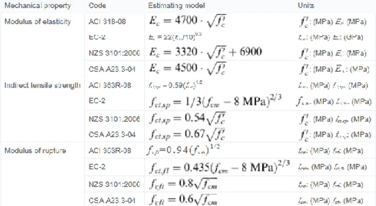
The properties analysed in this study are the modulus of elasticity, tensile strength and modulus of rupture. A comprehensive database of testing results was produced along with a survey of codes that currently exist for ordinary concrete. The codes that were used were: ACI, Eurocode 2, the New Zealand code NZS 3106:2006 and the Canadian code CSA A23.3-04 in order to obtain a representative, worldwide assessment. Figure 22 shows the formulae used by each code in determining each mechanical property (Vilanova et al, 2011).
Figure 22: Various formulae of relevant codes used to determine concrete’s mechanical properties
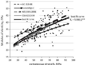
The values produced by the codes were plotted against one another, along with the SCC sample values and a line of best fit between theses sample values. The graphs for modulus of elasticity, indirect tensile strength and modulus of rupture can be seen in Figures 23, 24 and 25 respectively.
Figure 23: Graph showing MoE calculated using various codes compared to best fit line of SCC samples
Figure 24: Graph showing ITS calculated using various codes compared to best fit line of SCC samples
Figure 25: Graph showing MoR calculated using various codes compared to best fit line of SCC samples
Though not the best presented graphs, the relationship between the best fit line of the samples and the values given by each of the codes can be determined. For the modulus of elasticity, it can be seen that both the ACI and Canadian codes follow the line of best fit suitably. The Eurocode 2 code is too conservative whereas the New Zealand code underestimates the modulus of elasticity. For the graph representing the indirect tensile strength the Eurocode measurement seems to be the only code which is applicable. The Canadian code overestimates the tensile strength whereas the ACI and New Zealand codes both produce underestimates. The ACI code is the most appropriate for the modulus of rupture, albeit slightly conservative. All three of the other codes seem to vastly underestimate the value (Vilanova et al, 2011).
The dispersion of the codes is less than that of the samples indicating that they are each sufficient to predict the properties of SCC. It should also be mentioned however that the results were based on the compressive strength of the concrete. Other variables are not considered in this study which in SCC may prove to be crucial (Vilanova et al, 2011).
3.3
Formwork
Deliverable 9.1 provides information about the specific aspects that formwork design must adhere to as well as three potential suggestions for how this could be achieved. These suggestions are moulding by way of milled formwork created by CAD/CAM, moulded formwork manufactured using a wax/paraffin model and triangular formwork making use of many standardised parts in a non-standardised shape. In addition, a review of the four formwork design aspects is provided. These are geometric conditions, surface finishes, formwork pressure and choice of formwork material and system. This section of the report will investigate these aspects and document the findings of the literature study.
3.3.1 Formwork pressure
The ACI codes determine the lateral formwork pressure resulting from casting of self-compacting concrete to be equal to a full water head of concrete. This specification is seen to be undoubtedly safe, but it is too conservative and therefore uneconomical. Once a standardised method for determining the lateral pressure of SCC has been created, then the design force for the formwork can be reduced to below the hydrostatic pressure. Due to thixotropy, plastic concrete experiences stiffening as a result of thixotropy. This eases the pressure exerted onto the formwork and is not taken into account in current standards (Kim et al, 2011).
Kim et al propose an analytical model to determine the relationship between formwork pressure and placement rate when using SCC. This model characterises and defines as a material property, the lateral pressure response of concrete. The formwork pressure can be defined as a result of this material property when related to the placement rate of the concrete. A method for creating the formwork design load for SCC is proposed (Kim et al, 2011).
The model assumes formwork to be rigid and neglects the friction between the formwork wall and the fresh concrete. Although these have an impact, a conservative result is achieved. The given formula derived by Kim et al is given below. R is the placement rate, w is the weight of the concrete, a and b are coefficients determined by
the formwork pressure test which equate to a delayed coefficient and an instantaneous coefficient respectively (Kim et al, 2011)..
Figure 26 shows the lateral pressure produced by different placement rates.
Figure. 26: Lateral pressure history for various placement rates
This diagram shows that the lateral pressure increases with a quicker placement rate. Furthermore, the maximum pressure always takes place at tmax
regardless of the placement rate. The maximum lateral pressure is therefore independent of time in this instance, instead produced by material properties and placement rate. Kim et al proceed to suggest a design code for formwork used for SCC. This is produced as a result of testing SCC at a variety of placement rates (Kim et al, 2011).. The equation suggested is seen below:
σmax = 3.6wR
This is for SCC where w is the weight of the concrete and R is the placement rate.
3.3.2 Lateral pressure in geometrically complex formworks
Gallego et al developed a finite element model that simulates the lateral pressure resulting from complex shaped formworks. The model also includes information resulting from different mix types, their differing mechanical properties and differing coefficients of friction. The numerical results arising from a tall formwork that is filled at a high placement rate proved to be greater than that given in the codes, in some cases (Gallego et al, 2011).
The model was used on a V-shaped section of a bridge deck. The results of this were plotted along with the results produced by the ACI, CIRIA and DIN codes.
(16)
Figure. 27: V-shaped section of a bridge deck used for modelling
Figure. 28: Calculation of lateral pressure by means of 2D model, 3D model and various codes
The results obtained by modelling the pressure on the formwork of the V-shaped section through various methods are shown. The 3D finite element model put forward is shown in Figure 27, as is the 2D model in Figure 28 created in a previous publication (Gallego et al, 2010). The discrepancy in these two lines results from the redistribution of pressure in the z-direction that is not considered in the 2D model. The difference in the results produced by the codes and the models is due to the fact that the codes do not consider the tangential stress derived from the frictional forces between the mass of the concrete and the formwork. The authors suggest that the codes are shown to be excessively conservative at small and medium depths. Figure 29 reveals an example of how the model is capable of calculating the lateral forces at a variety of inclinations (Gallego et al, 2011).