2013:16
Technical Note
Assessment of
PWR
fuel depletion and
of neutron multiplication factors for
intact
PWR
fuel copper canisters
Main review phase
SSM perspektiv
BakgrundStrålsäkerhetsmyndigheten (SSM) granskar Svensk Kärnbränslehantering
AB:s (SKB) ansökningar enligt lagen (1984:3) om kärnteknisk verksamhet
om uppförande, innehav och drift av ett slutförvar för använt kärnbränsle
och av en inkapslingsanläggning. Som en del i granskningen ger SSM
kon-sulter uppdrag för att inhämta information och göra expertbedömningar i
avgränsade frågor. I SSM:s Technical note-serie rapporteras resultaten från
dessa konsultuppdrag.
Projektets syfte
Det övergripande syftet med projektet är att ta fram synpunkter på SKB:s
säkerhetsanalys SR-Site för den långsiktiga strålsäkerheten hos det
plane-rade slutförvaret i Forsmark. Detta uppdrag avser granskning av nukleär
kriticitetssäkerhet.
Författarens sammanfattning
SKB (Svensk Kärnbränslehantering AB) ansökte 2011 om svenska
regering-ens tillstånd för en föreslagen lösning för slutförvaring av använt bränsle från
svenska kärnkraftverk och en del mindre kvantiteter av annat fissilt material.
Denna Technical Note innehåller resultat från en färsk genomgång av
SKB:s metoder for att bestämma inverkan av reaktorutbränning på keff för
intakt PWR-bränsle i en intakt kopparkapsel flödad med vatten.
Granskningen har, så lång möjligt, baserats på allmän information i
ansö-kan, till skillnad mot den utvalda (och möjligen bearbetade) information
som finns I utvärderingen av kriticitetssäkerhet. Beräkningsmetoderna
(datorprogram och tvärsnittsdata) vid granskningen har varit annorlunda
än de som använts av SKB men det finns gemensamma felkällor.
Tillämp-barheten av granskningsmetoden baseras primärt på benchmarks för keff
och reaktivitet, till skillnad från benchmarks baserade på
materialsamman-sättningar som använts av SKB.
Granskningen har fokuserats på reaktorutbränning av PWR-bränsle och
av intakt kopparkapsel för intakt PWR-bränsle. Specifika händelseförlopp
kan utvärderas senare, med denna information som grund. Nyligen (2011)
publicerade benchmarks från Electric Power Research Institute (EPRI) har
utnyttjats. Tidigare och pågående studier av utbränningskreditering av
OECD/NEA ger värdefull information om utbränningsberäkningar från
tes-tade metoder. En pågående utvärdering av OECD/NEA (för
IRPhE-hand-boken med benchmarks) av mätningarna som ligger till grund för EPRI.s
benchmarks är värdefull (ett utkast förväntas bli publicerat vården 2013).
Det övergripande resultatet är att det inte tycks finnas något större hinder
vid bestämning av keff noggrant både för färskt och för bestrålat
PWR-bränsle i en intakt PWR-kapsel. Resultaten i SKB:s ansökan är trovärdiga,
inom de osäkerheter som specificeras. Nyligen publicerade och pågående
utvecklingsprojekt avseende benchmarks (både mätningar av integral
reaktivitet och av materialsammansättningar) för utbränningsmetoder kan
tillämpas för att minska osäkerheten ytterligare.
Projektinformation
Kontaktperson på SSM: Mikael Kjellberg
Diarienummer ramavtal: SSM2011-4444
Diarienummer avrop: SSM2012-3834
Aktivitetsnummer: 3030007-4038
SSM perspective
BackgroundThe Swedish Radiation Safety Authority (SSM) reviews the Swedish
Nu-clear Fuel Company’s (SKB) applications under the Act on NuNu-clear
Acti-vities (SFS 1984:3) for the construction and operation of a repository for
spent nuclear fuel and for an encapsulation facility. As part of the review,
SSM commissions consultants to carry out work in order to obtain
infor-mation and provide expert opinion on specific issues. The results from the
consultants’ tasks are reported in SSM’s Technical Note series.
Objectives of the project
The general objective of the project is to provide review comments on SKB’s
postclosure safety analysis, SR-Site, for the proposed repository at Forsmark.
Summary by the author
SKB (Svensk Kärnbränslehantering AB) in 2011 applied to the Swedish
government for approval of a proposed solution for disposal of used fuel
from Swedish nuclear power reactors and some relatively minor quantities
of other fissile material.
This Technical Note contains results of a recent review of the SKB
met-hods used to determine the influence of reactor depletion on keff of intact
PWR fuel in an intact PWR copper canister flooded with water.
The review has, as far as possible, been based on general information in the
licensing application, as opposed to the selected (and possibly modified)
information in the criticality safety evaluation. The review calculation
met-hods (computer codes and cross-section data) have been different than the
methods used by SKB, but there are some common error sources.
The review method validation is primarily based on keff and reactivity
benchmarks rather on composition benchmarks as used by SKB. The
review has focused on the reactor depletion of PWR fuel and of the intact
fuel in the intact PWR copper canister. Specific scenarios can be
evalua-ted later, with this information as a basis. Advantage has been taken of
recent (publication 2011) Electric Power Research Institute (EPRI)
bench-marks. Past and on-going burnup credit studies by OECD/NEA provide
valuable information on depletion calculations, often from validated
met-hods. An on-going evaluation by OECD/NEA (for the IRPhE handbook
with benchmarks) of the measurements involved in the EPRI benchmarks
is valuable (a draft is expected to be published in the spring of 2013).
The overall result is that there appears to be no major obstacles in
deter-mining keff quite accurately both for fresh and for depleted PWR fuel in
an intact PWR canister. The results in the SKB application are credible,
within the uncertainties specified. Recently published and on-going
validation developments for depletion method benchmarks (both
mea-surements of integral reactivity and of material compositions) might be
applied to reduce the uncertainty further.
2013:16
Author:Assessment of
PWR
fuel depletion and
of neutron multiplication factors for
intact
PWR
fuel copper canisters
Main review phase
Dennis MennerdahlE Mennerdahl Systems, Sweden
This report was commissioned by the Swedish Radiation Safety Authority
(SSM). The conclusions and viewpoints presented in the report are those
of the author(s) and do not necessarily coincide with those of SSM.
Contents
1. Introduction ... 3
2. Nuclear criticality safety criteria... 4
3. PWR fuel specification1 ... 4
3.1. PWR fuel types and specifications ... 4
3.2. Unirradiated PWR fuel assembly contents ... 8
3.3. Depleted PWR fuel assemblies ... 13
3.4. Selection of PWR fuel assemblies for canister ... 14
3.5. Burnup determination and assembly selection ... 15
3.6. Burnup loading curves ... 16
3.7. Canister types I, II and III ... 17
3.7.1. The PWR I type-canister ... 18
3.7.2. The PWR II type-canister... 19
3.7.3. The PWR III type canister ... 19
3.7.4. The PWR-MOX canister ... 20
4. Reactor operating data for the fuel ... 20
5. The copper canister specifications ... 23
6. Additional specifications in the SKB criticality safety report ... 33
7. SKB calculation methods ... 38
8. SKB calculations for the PWR canister ... 40
9. EMS calculation methods ... 42
9.1. General description of methods ... 42
9.2. Validation standards for calculation methods ... 43
9.3. Validation of keff calculation methods ... 45
9.4. Validation of fuel depletion methods ... 45
9.5. Validation of SCALE 6.1.1 keff calculations ... 46
9.6. Validation of SCALE 6.1.1 depletion calculations ... 47
9.6.1. OECD/NEA calculation benchmarks ... 47
9.6.2. EPRI and IRPhEP benchmarks ... 48
9.6.3. Recent NRC SFST ISG-8 Rev.3 validation approach ... 48
9.6.4. Summary of EMS validation of burnup credit methods ... 48
10. EMS review calculations ... 49
10.1.1. Purpose ... 49
10.1.2. Canister design ... 49
10.1.3. PWR fuel ... 51
10.1.4. PWR depletion in Ringhals 2, 3 and 4 ... 52
10.1.5. PWR depletion models ... 52
10.1.6. PWR canister models ... 53
10.1.7. Calculation cases ... 54
10.1.8. Calculation results ... 55
11. Comparisons of EMS and SKB results ... 57
12. The Consultant’s assessment ... 58
13. References ... 60
Appendix A. OECD/NEA/NSC/WPNCS ... 62
A.1. Phase I-B ... 62
A.2. Phase III-B ... 63
A.3. Phase IV-B ... 65
A.4. Phase II-D ... 67
A.5. Phase III-C ... 70
Appendix B. EPRI benchmarks ... 71
B.1. Introduction ... 71
Appendix C. IRPhE Handbook benchmark ... 75 Appendix D. Coverage of SKB reports ... 76
1. Introduction
The Swedish SKB (Svensk Kärnbränslehantering AB) has used burnup credit to support the nuclear criticality safety of the proposed final disposal of Swedish nuclear power reactor fuel. Burnup credit is a criticality safety term that refers to taking credit for a reduction in the multiplication factor (keff, an inverse eigenvalue
in the neutron transport equation) due to depletion (transmutation) of the nuclear fuel in the reactor and later radioactive decay. Burnup credit is a criticality safety control implemented by management decision.
This Technical Note is not a nuclear criticality safety review. However, it covers important components of a nuclear criticality safety review of an intact water-filled copper canister for PWR fuel. Important issues include:
The specifications of the fuel
The specifications of the fuel history (primarily during reactor operation)
The specifications of the canister
Selection of a calculation method
Validation of the calculation method
Independent calculations of depletion effects and of keff values
Comparison with the SKB safety assessment
Further suggestions for criticality safety review
In addition to the burnup credit for the copper canister, SKB currently applies burnable absorber (BA) credit to BWR fuel in the CLAB facility. BA credit is not burnup credit. Depletion consideration is required for used BWR fuel with BA credit. Depletion consideration related to burnup credit for used BWR fuel with or without BA is optional.
There are many other systems than the intact canister with PWR fuel and there are other issues that need to be included in a complete criticality safety review. The other issues include impact of the human factor (e.g. misloading of fuel), impact of potential incidents, damage and long-term degradation to the fuel and to the canister. They need to be reviewed later since this initial phase focuses on calculation methods and accuracy in determining keff for the intact, water-filled PWR canister.
The results should be applicable to future reviews involving burnup credit and BA credit for used nuclear fuel.
Chapters 2-8 contain information, often directly copied, from the SKB source documents. All information in this report is based on publicly available information. That information has been screened to fit the purpose of the report and apparent editorial errors and inconsistencies have been corrected. Sometimes the text is an interpretation of the information in the source documents. There may thus be some differences between information in chapters 2-8 compared with the source documents.
The compilation of information from the safety documentation is a part of the review method. That compilation has not been reviewed in detail and should not be used as a source for other work or for safety-related decisions.
2. Nuclear criticality safety criteria
1
The SKB criticality safety design criteria are summarized in chapter 3, section 2.1.2 of SKBdoc 1091554 (reference 1):
”Anläggningen, dess system och komponenter ska konstrueras att motstå felfunktion, yttre och inre belastningar så att en händelse som kan leda till en radiologisk olycka med radioaktivt utsläpp har en frekvens som är mindre än 10-6/år. Detta innebär att för alla konstruktionsstyrande händelser ska kopparhöljets täthet bibehållas.”
The author’s translation of the criticality safety requirement in the same section 2.1.2 is: “The canister internal geometry and the contained fuel shall for all design basis events for the repository comply with a safety margin such that keff < 0.95.”
Appendix 1 (page 2) in SKBdoc 1091152 (reference 2): ”Kriticitet ska under inga förutsättningar kunna uppstå, oavsett hur bränslet är disponerat i kapseln (krav på inkapslingsanläggningen). Kriticitet ska inte kunna vara en händelse som är aktuell för slutförvaret. I slutförvarsanläggningen ska det kunna visas att händelser med stor retardation/acceleration inte kan leda till kriticitet.”
Chapter 8, section 1.3.4 of SKBdoc 1091141 (reference 3) states:
”Kriticitetshändelser i slutförvaret kan därmed inte uppstå. Verifiering att denna dimensioneringsförutsättning för slutförvaret är uppfyllt redovisas i [4].” The [4] in this quote is a reference in that report: “[4] SKB 2009. Design premises for a KBS-3V repository based on results from the safety assessment SR-Can and some subsequent analyses, SKB TR-09-22”
3. PWR fuel specification
1
3.1. PWR fuel types and specifications
A number of suppliers of nuclear fuels have been and will be used by the different nuclear power plants. The detailed design of the assemblies can vary between suppliers; see Appendix A in TR-10-13 (the Spent Fuel Report, reference 4). Appendix A contains information about existing PWR fuel types in Sweden at the end of 2008. There are minor variations not specified in that Appendix A but the main types are representative.
The information is repeated in Tables 1 and 2. Table 2 is based on Table A-4 of TR-10-13 (which refers to SKBdoc 1193244, reference 5). The selected information from TR-10-13 is assumed to be correct, except for some minor uncertainties and some editorial changes marked by the author in red in Table 2. The source documents for the information are referred to in Table 22 footnotes which are obtained from Appendix 3 of SKBdoc 1193244. Some of the specifications in Table 2 (from TR-10-13) are different to Table 22 (from SKBdoc 1193244) specifications and may be more accurate since they are results of further checks. The uncertain specifications are marked in red in both Tables 2 and 22.
There are no geometry specifications for PWR MOX fuel available to the author during this review.
Table 3 contains design information on limiting fuel parameters that have been observed by SKB. The information is needed to design and test the inserts for the copper canisters.
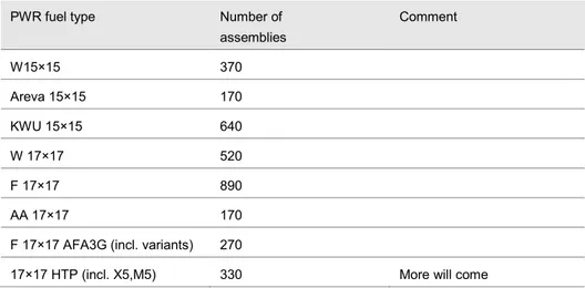
Table 1: PWR fuel types (from Table A-1 of SKB TR-10-13)
PWR fuel type Number of
assemblies Comment W15×15 370 Areva 15×15 170 KWU 15×15 640 W 17×17 520 F 17×17 890 AA 17×17 170
F 17×17 AFA3G (incl. variants) 270
17×17 HTP (incl. X5,M5) 330 More will come
“The PWR fuel assemblies contain 204 or 264 fuel rods, arranged in square arrays. The cross-sectional area is about 0.214×0.214 m2 and the total length is about 4.3 m. Figure 1 shows a model of a PWR fuel assembly.” (Section 2.3.2 of TR-10-13).
Figure 1: A PWR fuel assembly. (SKB TR-10-13, Figure 2-5)
IV
V
VI
I
II
III
I
Length ~4.3 m
II
Maximum cross section area
214×214 mm
III
Control rod cluster
IV
Guide tube for control rod
V
Fuel rod
Table 2: PWR fuel type specifications (from Table A-4 of SKB TR-10-13).1
Fuel type W15x15 KWU15x15 F15x15
AFA3G 15x15 AGORA W17x17 AA17x17 F17x17 S17x17 HTP 17x17 HTPX5 17x17 HTP M5 17x17 HTP X5 17x17 AFA3G
No of fuel rods 204 204 204 204 264 264 264 264 264 264 264 264
Fuel rod pitch (mm) 14.3 14.3 14.3 14.3 12.6 12.6 12.6 12.6 12.6 12.6 12.6 12.6
Fuel rod outer diameter (mm) 10.72 10.75 10.72 10.77 9.5 9.5 9.5 9.55 9.55 9.5 9.5 9.5
Fuel rod inner diameter (mm) 9.48 9.3 9.484 9.505 8.36 8.36 8.36 8.33 8.33 8.364 8.35 8.355
Cladding thickness (mm) 0.62 0.725 0.618 0.6325 0.57 0.57 0.57 0.61 0.61 0.568 0.575 0.5725
Pellet diameter (mm) 9.20 9.11 9.294 9.33 8.19 8.19 8.19 8.17 8.165 8.192 8.192 8.192
Cladding material Zr4 Zr4 M5 Zr4 Zr4 Zr4 Zr4 Zr4 Zr4 M5 M5 Zr4
Active fuel length (mm) 3658 3658 3658 3658 3658 3658 3658 3658 3658 3658 3658 3658
UO2 density (g/cc)* 10.7 10.7 10.7 10.7 10.7 10.7 10.7 10.7 10.7 10.7 10.7 10.7
No of guide tubes 20 20 20 20 24 24 24 24 24 24 24 24
Guide tube material Zr4 Zr4 M5 M5 Zr4 Zr4 Zr4 PCAm PCAm PCAm PCAm Zr4
Guide tube outer diameter (mm) 13.87 13.86 14.1 14.1 12.09 12.24 12.05 12.24 12.45 12.45 12.24 12.45 Guide tube inner diameter (mm) 13.01 13 13.05 13.05 11.05 11.44 11.25 11.3 11.45 11.45 11.3 11.45
Guide tube cladding thickness (mm) 0.43 0.43 0.525 0.525 0.52 0.4 0.4 0.47 0.5 0.5 0.47 0.5
No of instrument tubes 1 1 1 1 1 1 1 1 1 1 1
Instrument tube material Zr4 Zr4 M5 M5 Zr4 Zr4 Zr4 PCAm PCAm PCAm PCAm Zr4
Instrument tube outer diameter (mm) 13.87 13.86 14.1 14.1 12.24 12.24 12.05 12.24 12.24 12.45 12.24 12.45 Instrument tube inner diameter (mm) 13.01 13.03 13.05 13.05 11.428 11.428 11.25 11.3 11.3 11.45 11.3 11.45 Instrument tube cladding thickness (mm) 0.43 0.43 0.525 0.525 0.406 0.406 0.4 0.47 0.47 0.5 0.47 0.5 * The UO2-density 10.7 g/cc is used for all fuel types. This density is higher than the fabricated values.
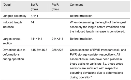
Table 3: “Design measures for the fuel channel tubes of the insert” (Table 3-1 in SKB TR-10-13) “Detail BWR (mm) PWR (mm) Comment Longest assembly 4,441 Before irradiation Induced length
increase
14 When determining the length of the longest assembly the length before irradiation and the induced length increase is considered. Largest cross section 141×141 214×214 Before irradiation. Deviations due to deformations during operation
145.5×145.5 228×228 Cross sections of BWR transport cask, and PWR storage canister respectively. All assemblies in Clab have been placed in these casks or canisters, i.e. these cross sections are sufficient with respect to occurring deviations due to deformations during operation”
3.2. Unirradiated PWR fuel assembly contents
Typical contents of an unirradiated PWR fuel assembly are presented in Table 4. Other enrichments will give different weights. Typical impurities are presented in Table 5; structural components in the fuel assembly are presented in Table 6 while the control rod clusters are specified in Table 7. The information in Tables 5-7 is more extensive than what is needed for depletion and criticality safety assessment. Table 4: Unirradiated fuel contents in a PWR fuel assembly (from Table B-1 of TR-10-13)
PWR AREVA 17x17 4.0 (% U-235)
Weight in one fuel assembly (kg) Fuel U-tot 464 U-2341 0.19 U-2351 18.6 U-2361 0.1 U-2381 445.2 O 62
Cladding material Zirconium alloys 108 Stainless steel 3 Other constructions
(bottom and top plate, spacers etc.)
Stainless steel 12 Zirconium alloys 21
Nickel alloys 2
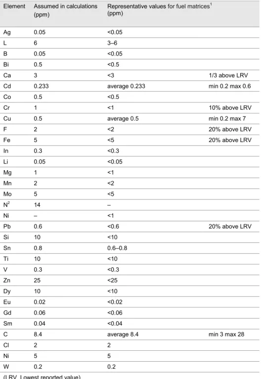
Table 5: “Impurities in the fuel matrix” (Table B-2 of SKB TR-10-13)
Element Assumed in calculations
(ppm) Representative values for fuel matrices
1 (ppm) Ag 0.05 <0.05 L 6 3–6 B 0.05 <0.05 Bi 0.5 <0.5 Ca 3 <3 1/3 above LRV
Cd 0.233 average 0.233 min 0.2 max 0.6
Co 0.5 <0.5
Cr 1 <1 10% above LRV
Cu 0.5 average 0.5 min 0.2 max 7
F 2 <2 20% above LRV Fe 5 <5 20% above LRV In 0.3 <0.3 Li 0.05 <0.05 Mg 1 <1 Mn 2 <2 Mo 5 <5 N2 14 – Ni – <1 Pb 0.6 <0.6 20% above LRV Si 10 <10 Sn 0.8 0.6–0.8 Ti 10 <10 V 0.3 <0.3 Zn 25 <25 Dy 10 <10 Eu 0.02 <0.02 Gd 0.06 <0.06 Sm 0.04 <0.04
C 8.4 average 8.4 min 3 max 28
Cl 2 2
Ni 5 5
W 0.2 0.2
(LRV_Lowest reported value)
1 Personal communication Westinghouse. 2 Assumed in accordance with /SKBdoc 1179234/.
Table 6: PWR fuel assembly component materials (Table B-4 of SKB TR-10-13)
Compon-ent Top nozzle
SS Top nozzle Zr Bottom nozzle SS Spacer Zr Spacer inconel Guide thimble Zr Guide thimble SS Cladding Zr Cladding SS1 Material 304L_1 Inc718
_1 304L_2 Zry4_3 Inc718_3 Zry4_4 316L_4 M5_5 302_5 Weight (kg) 6.5 1.1 4.8 7.2 0.75 14.2 0.7 108.1 3 Material Composition (%) Li 0.00001 0.00001 0.00001 0.00001 C 0.02 0.03 0.02 0.015 0.03 0.015 0.025 0.015 0.12 N 0.04 0.01 0.04 0.004 0.01 0.004 0.04 0.004 0.04 O 0.01 0.01 0.01 0.14 0.01 0.14 0.01 0.14 0.01 Na 0.001 0.001 0.001 0.001 Al 0.002 0.5 0.002 0.005 0.5 0.005 0.002 0.005 0.002 Si 0.6 0.3 0.6 0.01 0.3 0.01 0.6 0.01 0.6 P 0.02 0.005 0.02 0.005 0.02 0.02 S 0.015 0.005 0.015 0.005 0.015 0.015 Cl 0.0001 0.0001 0.0001 0.0001 0.0001 0.0001 Ca 0.002 0.002 0.002 0.002 Ti 0.01 0.9 0.01 0.004 0.9 0.004 0.01 0.004 0.01 V 0.001 0.01 0.001 0.01 0.001 0.001 Cr 18.5 19 18.5 0.1 19 0.1 17 18.5 Mn 1.3 0.3 1.3 0.003 0.3 0.003 1.3 1.3 Fe 69.05 21.05 69.05 0.22 21.05 0.22 66.25 69.95 Co 0.03 0.05 0.03 0.0001 0.05 0.0001 0.03 0.00001 0.03 Ni 10 52.5 10 0.004 52.5 0.004 12 9 Cu 0.1 0.1 0.1 0.003 0.1 0.003 0.1 0.1 Zn 0.01 0.01 0.01 0.01 As 0.01 0.05 0.01 0.05 0.01 0.01 Se 0.004 0.004 0.004 0.004 Nb 0.03 4.59 0.03 0.01 4.59 0.01 0.03 1 0.03 Mo 0.2 0.05 0.2 0.0005 0.05 0.0005 2.5 0.2 Ag 0.0001 0.0001 0.0001 0.0001 Sn 0.01 0.01 0.01 1.5 0.01 1.5 0.01 0.01 Sb 0.001 0.005 0.001 0.005 0.001 0.001 Ce 0.01 0.01 0.01 0.01 Ta 0.01 0.51 0.01 0.51 0.01 0.01 W 0.01 0.01 0.01 0.005 0.01 0.005 0.01 0.005 0.01 Hf 0.006 0.006 0.01 Zr 0.001 97.97 97.97 98.81 Th 0.00002 0.00002 0.00002 U 0.00015 0.00015 0.00015
Table 7: PWR fuel assembly control rod cluster contents (Table B-5 of SKB TR-10-13)
Component Absorber pins Absorber pins Top piece
Material 304_1 AgInCd_1 304_2 Weight (kg) 12.5 51.4 3.8 Material composition (%) Li 0.00001 0.00001 C 0.07 0.07 N 0.04 0.04 O 0.01 0.01 Na 0.001 0.001 Al 0.002 0.002 Si 0.6 0.6 P 0.02 0.02 S 0.015 0.015 Cl 0.0001 0.0001 Ca 0.002 0.002 Ti 0.01 0.01 V 0.001 0.001 Cr 18.5 18.5 Mn 1.3 1.3 Fe 68.9 68.9 Co 0.1 0.1 Ni 10 10 Cu 0.1 0.1 Zn 0.01 0.01 As 0.01 0.01 Se 0.004 0.004 Nb 0.03 0.03 Mo 0.2 0.2 Ag 0.0001 80 0.0001 Sn 5 Sb 15 Ce 0.01 0.01 Ta 0.001 0.001 W 0.01 0.01 Hf 0.01 0.01 Zr 0.01 0.01
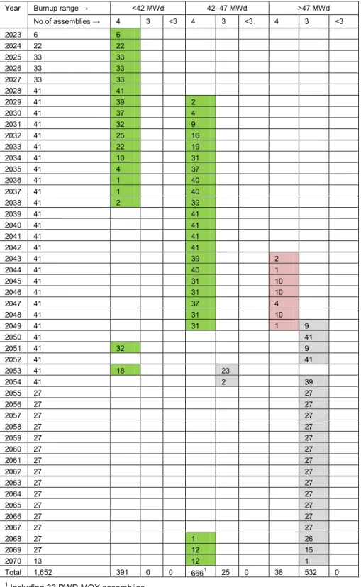
Table 8 shows distributions of PWR canisters to be disposed of per year and canister type. Green background refers to 1057 PWR I type canisters. Red background refers to 38 PWR II type canisters and grey background to 557 PWR III type canisters. A canister type specifies a range of burnup values and decay times of the fuel in the canister. More information is provided in chapter 3.7 of this Technical Note.
Table 8: PWR canisters/year during 2023–2070 (PWR data from Table C-4 of SKB TR-10-13)
Year Burnup range → <42 MWd 42–47 MWd >47 MWd No of assemblies → 4 3 <3 4 3 <3 4 3 <3 2023 6 6 2024 22 22 2025 33 33 2026 33 33 2027 33 33 2028 41 41 2029 41 39 2 2030 41 37 4 2031 41 32 9 2032 41 25 16 2033 41 22 19 2034 41 10 31 2035 41 4 37 2036 41 1 40 2037 41 1 40 2038 41 2 39 2039 41 41 2040 41 41 2041 41 41 2042 41 41 2043 41 39 2 2044 41 40 1 2045 41 31 10 2046 41 31 10 2047 41 37 4 2048 41 31 10 2049 41 31 1 9 2050 41 41 2051 41 32 9 2052 41 41 2053 41 18 23 2054 41 2 39 2055 27 27 2056 27 27 2057 27 27 2058 27 27 2059 27 27 2060 27 27 2061 27 27 2062 27 27 2063 27 27 2064 27 27 2065 27 27 2066 27 27 2067 27 27 2068 27 1 26 2069 27 12 15 2070 13 12 1 Total 1,652 391 0 0 6661 25 0 38 532 0
3.3. Depleted PWR fuel assemblies
The maximum assembly average burnup for PWR fuel with uranium oxide (UOX) fuel is specified as 60 MWd/kgU (TR-10-13 Section 2.1.1).
The following PWR UOX data are obtained from Table 2-2 in TR-10-13: PWR UOX
Year 2045 from the reactors R2, R3 and R4 6,016 assemblies
31 December 2007 from R2, R3 and R4 2,552 assemblies
Assumed weight U per assembly: 464 kg
The following PWR MOX data are obtained from Table 2-2 and text on swap MOX fuel in Section 2.2.2 in TR-10-13:
PWR MOX
Swap from Germany 33 assemblies
Initial mass of actinides: 8.4 ton.
The average burnup is: 31 MWd/kg initial actinides
The following two quotes are from the second paragraph in Section 2.2.1 in TR-10-13:
“Approximately one out of four of the PWR assemblies will contain a control rods cluster”.
“Since the beginning of 1970 the burnup of the nuclear fuel has increased from approximately 23 MWd/kgU up to 53 MWd/kgU. The average burnup of the PWR fuel stored in the interim storage facility is about 41 MWd/kgU (December 2007). For the remaining operation, the burnup will increase as a result of increased power and optimisation of the operation of the reactors.”
The third paragraph of the same Section states that the resulting average burnup for the reference scenario is 44.8 MWd/kgU for PWR fuel assemblies (a reference to SKBdoc 1221579 is made).
The burnup distribution of PWR fuel stored in Clab on 31 December 2007 and a prognosis for future PWR fuel burnup values are presented in Figure 2.
Figure 2: PWR fuel assembly burnup distributions (SKB TR-10-13, Figure 2-1)
<10 10–20 20–30 30–40 40–50 50–60 0 500 1000 1500 2000 2500 3000 3500 N u m b e ro f PW R fu e l a s s em b l i e s Burnup intervals (MWd/kgHM) PWR Prognosis PWR Produced
Figure 3: PWR fuel assembly ages. (SKB TR-10-13, Figure 2-4)
In Figure 3 the PWR “assemblies stored in Clab at the end of 2007 and the assemblies included in the reference scenario and their burnup and age are plotted for 2045, i.e. the last year of operation of the last reactor to close down”. “For the assemblies included in the reference scenario large red dots represent the batch average discharge burnup. The smaller red dots represent the assumed standard deviation in burnup, i.e. ±3 MWd/kgU, averaged over single fuel assemblies included in a batch. Each dot represents several assemblies. Low burnup assemblies in the reference scenario are from the last year of operation of the nuclear power plants.” (The above quotes are from the text preceding Table 2-2 in TR-10-13)
3.4. Selection of PWR fuel assemblies for canister
Criticality safety related requirements and criteria for the selection of fuel assemblies to be encapsulated include the following:
“Requirement on handling: The fuel assemblies to be encapsulated shall be
selected with respect to enrichment, burnup, geometrical configuration and materials in the canister so that criticality will not occur during the handling and storage, even if the canister is filled with water.
Criterion: The effective multiplication factor (keff) must not exceed 0.95 including uncertainties.”
(from Section 3.1.2 in TR-10-13)
Requirement on handling: Before the fuel assemblies are placed in the
canister they shall be dried so that it can be justified that the allowed amount of water stated as a design premise for the canister is not exceeded. Criterion: The amount of water left in anyone canister shall be less than
“Requirement on handling: Before the canister is finally sealed, the
atmosphere in the insert shall be changed so that acceptable chemical conditions can be ensured.
Criterion: The atmosphere in canister insert shall consist of at least 90%
argon.”
(From Section 3.1.4 in TR-10-13)
“Requirement on handling: The number of canisters shall be minimised
and, if possible, all assembly positions in the deposited canisters shall be filled.”
(from Section 3.2.1 in TR-10-13)
“The selection process can be summarised as follows.
1. Compile information for the selection.
2. Preliminarily selection – based on decay power and the objective to fill all assembly positions in the canisters to be deposited.
3. Check criticality – adjust the selection in case of non-conformity to the criterion for criticality.
4. Check radiation dose rate on the canister surface – adjust the selection in case of non-conformity to the criterion for maximum allowed radiation dose rate.
5. Lifts and movements – investigate the number of lifts and movements of
assemblies and storage canisters and adjust the selection if the number of lifts can be reduced and the selection still conforms to criteria for decay power and criticality.
6. Final selection – determine a selection and make a plan for transport of storage canisters and assemblies.”
(From Section 4.1.1 in TR-10-13)
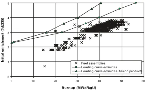
“Criticality safety is checked by calculating loading curves” (text after Figure 4-2 in TR-10-13). “The calculated loading curves and the combinations of average burnup and enrichment for the assemblies that currently are stored in Clab are given in Figure” 4. “Fuel assemblies with a combination burnup/enrichment that are plotted above the loading curves in Figure “4 “may result in a canister keff that exceeds 0.95
and will thus not conform to the general criterion for criticality” safety (quotes from paragraph before Figure 4-3 in TR-10-13).
3.5. Burnup determination and assembly selection
The process of selecting appropriate fuel assemblies for encapsulation is extremely important for safety and efficiency. The following quote from Section 4.2.2 of TR-10-13 is descriptive: “Regarding the burnup SKB intends to use data provided by the nuclear power plants. The burnup must be regularly calculated and accurately measured to achieve a reliable and efficient operation of the reactors. The
registration of burnup during operation is required by the Swedish Radiation safety authority (SSM) and the data is quality assured. If required, the burnup can also be measured by γ‑scanning.”
3.6. Burnup loading curves
Figure 4: Loading curves for PWR-canisters for assemblies currently stored in Clab (SKB
TR-10-13, Figure 4-4).
The following three paragraphs are based on text in Section 4.4.1 of TR-10-13 under “Check of criticality”.
After the primary selection based on the decay power has been made, the criteria to avoid criticality are checked. If keff < 0.95 for canisters3 with identical assemblies of
each type to be stored in the canister, i.e. the combination of enrichment and burnup, lies under the calculated loading curve, the assemblies can be encapsulated without further checks.
There will be canisters with keff > 0.95 if loaded with identical assemblies having
some specific characteristics. Such assemblies will not comply with the loading curve. In such cases, the keff value may be calculated for the actual set of selected
assemblies. In these calculations, an assembly potentially causing a keff > 0.95 is
placed in the canister in the worst position for potential criticality. If the calculations show that keff is still above 0.95 for the canister, that selection of assemblies is not
encapsulated.
If it is not possible to find a set of assemblies that conform to the general criticality safety criteria, a low burnup assembly can be encapsulated alone in a canister. Should it neither be possible to combine the low burnup assemblies with high burnup assemblies nor to encapsulate such assemblies individually to conform to the criticality criteria, the ultimate measure is to alter the geometry, i.e. to reconstruct the assembly.
3 TR-10-13 refers to assemblies rather than canisters with k
eff related to 0.95 0 1 2 3 4 5 0 10 20 30 40 50 60 Burnup (MWd/kgU) In iti a l e n ri c h m e n t (% U 2 3 5 ) Fuel assemblies Loading curve-actinides
3.7. Canister types I, II and III
Three types of canisters for PWR UO2 fuel have been used by SKB to select fuel
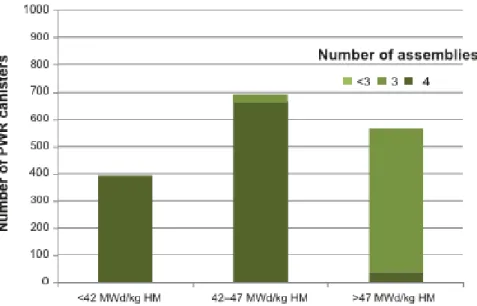
assemblies for encapsulation. Canister data are provided in Table 8 as well as in Figure 5 and Figure 6.
Figure 5: PWR canisters in groups with average burnup and assemblies per canister shown
(SKB TR-10-13, Figure 5-3).
SKB has identified a total of eight types of canisters, four of each for PWR (PWR
MOX fuel is added to the UO2 fuels) and BWR fuel assemblies, as shown in Figure
6. According to Section 6.2.4 of TR-10-13, the selection of type canisters is made based on the burnup of the assemblies since it is the main parameter determining the radionuclide inventory:
The PWR I canister has been selected since it represents the average
canister resulting from the simulation of the encapsulation of the assemblies to be deposited.
The high burnup PWR II canister has been selected since it represents the
high end canisters with respect to radionuclide inventory.
The PWR III canister has been selected to represent the unfilled canisters,
which are the result of the current decay power criterion and assumed encapsulation period.
Finally, the PWR MOX canister has been selected to represent the canisters
Figure 6: BWR and PWR canister inventory per canister type (SKB TR-10-13, Figure 6-1)
3.7.1. The PWR I type-canister
The following quotes are from Section 6.2.4 in TR-10-13:
“The average burnup of the assemblies in this canister is 44.8 MWd/kgU and the radionuclide inventory is regarded to be representative for all canisters where four PWR assemblies with different burnup and age have been combined so that their total decay power is 1,700 W and their average burnup lies in the interval 42–47 MWd/kgU. The PWR I type canister also represents full canisters with an average burnup of the assemblies less than 42 MWd/kgU. Assuming the same radionuclide inventory in these canisters as in the PWR average canister will result in an overestimated but still adequate inventory.”
The age of each assembly is at least 38 years (Table C-7 in TR-10-13).
A summary of the canisters, for which the PWR I canister is considered to provide an adequate description of the radionuclide inventory, is given in Table 9. Table 9: PWR canister type I statistics (Table 6-9 in SKB TR-10-13)
Radioactive inventory Representative Overestimated but adequate Total Number of canisters 633 391 1,024 Part of PWR canisters (1,652) 38% 24% 62%
3.7.2. The PWR II type-canister
The following quotes are from Section 6.2.4 in TR-10-13:
“The radionuclide inventory in the PWR II type-canister is set to the inventory in the canister denominated “PWR high burnup”. “The average burnup of the assemblies in this canister is 57 MWd/kgU. With respect to the total inventory of assemblies to be deposited, the applied criteria for selection of assemblies and the assumed period for encapsulation and deposition, the radionuclide inventory in the PWR II canister is regarded as the high end of the PWR canisters to be deposited”.
”The radionuclide inventory in the PWR II canister represents all canisters where PWR assemblies with different burnup and age have been combined so that their total decay power is 1,700 W and their average burnup is at least 45 MWd/kgU. In most of these canisters, the average burnup of the assemblies will be less than 57 MWd/kg/U. A summary of the canisters, for which the PWR II canister is
considered to provide an adequate description of the radionuclide inventory, is given in Table” 10.
The age of each assembly is at least 55 years (Table C-11 in TR-10-13). Table 10: PWR canister type II statistics (Table 6-10 in SKB TR-10-13)
Representative radionuclide inventory
Number of canisters 38 Part of PWR canisters (1,652) 2% Part of all canisters (6,110) 1%
3.7.3. The PWR III type canister
The following quotes are from Section 6.2.4 in TR-10-13:
“The radionuclide inventory in the PWR III type-canister is set to the inventory in the canister denominated “PWR combination b””. “The PWR III canister represents all PWR canisters with three assemblies. Based on the results from the simulation of the encapsulation, there are no PWR canisters with less than three assemblies. The average burnup of the assemblies in this canister is 57 MWd/kgU. The bulk of the canisters with three assemblies will have an average burnup lower than this. The content of short lived fission and activation products mainly depends on the burnup and age of the assemblies and will be similar as for the full canisters. The content of transuranium elements and isotopes with long half-lives will mainly depend on the encapsulated mass of uranium and will, thus, be lower than in the canisters that contain four assemblies. The number of canisters containing three assemblies is given in Table” 11.
One of the PWR assemblies has an age of at least 20 years while the other two assemblies have ages of at least 51 years (Table C-12 in TR-10-13).
Table 11: PWR Canister type III statistics (Table 6-11 in SKB TR-10-13)
Representative radionuclide inventory and total
Number of canisters 557 Part of PWR canisters (1,652) 34% Part of all canisters (6,110) 9%
3.7.4. The PWR-MOX canister
The following quotes are from Section 6.2.4 in TR-10-13:
“The radionuclide inventory in the PWR-MOX type-canister is set to the inventory in the canister denominated “PWR-MOX””. “Each PWR-MOX canister contains one swap PWR MOX assembly. The burnup of the MOX assembly is set to 34.8 MWd/kg actinides, which is the maximum burnup of the swap PWR MOX assemblies. The burnup of the remaining three assemblies in the canister is 44.8 MWd/kgU, i.e. the average PWR assembly burnup. The radionuclide inventory in the PWR-MOX canister is regarded to be representative for all PWR canisters containing a MOX assembly.
A summary of the canisters, for which the PWR-MOX canister is considered to provide an adequate description of the radionuclide inventory, is given in Table” 12. The age of the MOX assembly is at least 57 years and the age of each UO2 assembly
is at least 32 years (Table C-13 in TR-10-13).
Table 12: PWR MOX-canister statistics (Table 6-12 in SKB TR-10-13)
Representative radionuclide inventory Number of canisters 33
Part of PWR canisters (1,652) 2% Part of all canisters (6,110) 1%
4. Reactor operating data for the fuel
4
The Spent fuel report (TR-10-13) is based on a reference scenario for the future operation of the nuclear power plants and also includes the spent fuel that is stored in the interim storage facility. Alternative scenarios for the operation of the nuclear power plants are not included.
The batch average discharge burnup values for the ten remaining Swedish nuclear power plants that are assumed in the reference scenario used by SKB are presented in SKBdoc 1219727, ver 2.0. (“Confidential information. Available only for the Swedish Radiation Safety Authority.”)
Some reactor operating data and typical axial profiles are specified in SKBdoc 1193244. Some of that information is quoted later in chapter 8 of this Technical Note. Table 13 provides some reactor data that may be of relevance (e.g. increased power) to criticality safety.
At this time it is not clear to the author what information will be useful to assess and control criticality safety for the copper canister. The need for detail will depend on the need to have a small subcritical margin (the safety margin is a different issue, always need to be significant). Some information on relationships between reactor operation and fission gas release may be of value. Section 6.3 in TR-10-13 provides information that is summarised below. Figure 7 and Figure 8 provide some data on fission gap release.
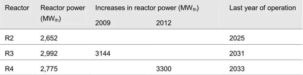
Table 13: Thermal reactor power and last year of operation for the Swedish PWRs (From
Table 2-1 in SKB TR-10-13) Reactor Reactor power
(MWth)
Increases in reactor power (MWth) Last year of operation
2009 2012
R2 2,652 2025
R3 2,992 3144 2031
R4 2,775 3300 2033
The power history, i.e. the power developed per length unit of fuel rod or fuel assembly over the irradiation period in the reactor vessel, referred to as the linear heat generation rate, is strongly correlated to the fission gas release (FGR). The FGR in turn is used to determine the part of the radionuclide inventory that is located at the fuel grain boundaries and in the gap between the fuel and the cladding. This part of the inventory is referred to as the gap inventory and will in comparison to the radionuclides embedded in the fuel matrix be released very rapidly if the spent fuel pellets are exposed to vapour or water.
Figure 7: “Calculated average fission gas release at the end of each cycle for PWR cases”
(SKB TR-10-13, Figure 6-3). 0 1 2 3 4 5 6 7 8 9 0 40 0 0 A v e ra g e F GR ( % )
Average burnup (MWd/kgU)
R2 Equilibruim R2 Cycle 33 R4 Equilibrium R4 Cycle 26
The relations illustrated in Figure 7 “are used to extrapolate reactor-specific relations between average burnup and FGR. In the interpolation, the numbers of assemblies in the reactors and their thermal powers have been considered. The relations are based on the assumption that the FGR is correlated to the linear heat generation. The interpolated relations between burnup and FGR have then been used to estimate the FGR of the spent fuel assemblies included in the reference scenario for the operation of the nuclear power plants” (from text following Figure 6-3). “The drop in burnup and FGR for R2 (Ringhals 2) Cycle 33 is explained by that only the low burnup assemblies were loaded in the last cycle.” (From Figure 6-3 title). The following quotes are from Section 6.3.1 of TR-10-13:
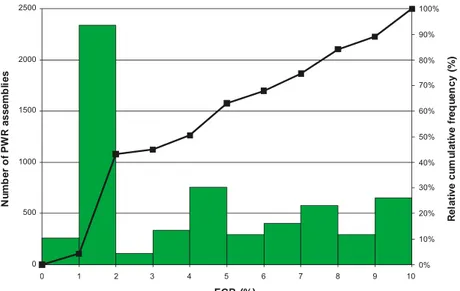
“From the average burnup of each assembly, the reactor it has been used in, and whether it was used before or after the increase in power, the extrapolated reactor-specific relations were used to estimate the FGR in each individual assembly.” “The resulting average FGR for all PWR assemblies is 4.3% with a standard deviation of ±3.11%. The number of PWR assemblies in different FGR intervals is illustrated in Figure” 8
Figure 8: PWR assemblies in FGR intervals and FGR relative cumulative frequency (SKB
TR-10-13, Figure 6-5)
“For the PWR-MOX canister the FGR was not estimated since the information required to estimate reactor-specific relations between burnup and FGR was not available for the German reactors from which the PWR-MOX assemblies originate. With respect to the low burnup of the MOX assembly and an average burnup close to that of the PWR I canister, the FGR in these canisters can be assumed to be similar or less than in the PWR I type canister.” (From Section 6.3.2 of TR-10-13).
0% 10% 20% 30% 40% 50% 60% 70% 80% 90% 100% 0 500 1000 1500 2000 2500 0 2 3 4 5 6 7 8 9 10 R e la ti v e c u m u la ti v e f re q u e n c y ( % ) N u m b e r o f P W R a s s e m b li e s FGR (%) 1
5. The copper canister specifications
5
The specifications for the copper canister are expected to be provided in a general part of the safety documentation, not only in the criticality safety part. In the SKB documentation for the application, this information appears to be compiled mainly in the Canister production report 10-14, reference 6) and in the Data report (TR-10-52, reference 7).
The maximum total weight of the canister, including fuel, is 26,800 kg for PWR, see Table 14.
Table 14: “Weight of the canisters” (Table 3-1 in SKB TR-10-14).
PWR fuel type Weight (kg)
BWR-canister PWR-canister
Insert with lid 13,700 16,400
Copper shell 7,500 7,500
Canister without fuel 21,200 23,900
Canister with fuel 24,600–24,700 26,500–26,800
“The canister comprises the following components which are detailed in the following sections: cast iron insert with steel tube cassette, steel lid, copper tube, copper lid and copper base, see Figure” 9 (quoted from Section 3 in TR-10-14). “the copper shell, i.e. tube, lid and base, are made of highly pure copper. The copper components are welded together by friction stir welding (FSW). To facilitate handling of the canister, the copper lid is provided with a flange to allow handling equipment to grip the canister.” (Section 3.2 in TR-10-14). “The insert is
manufactured of nodular cast iron with steel channel tubes in which the fuel assemblies are to be positioned.” (Section 3.1 in TR-10-14).
The following quotes from Section 3 of TR-10-14 are selected: “The reference canister design comprises” one insert “for 4 PWR fuel assemblies”. “The reference design is described by a set of design parameters for which nominal values and acceptable variations are given.”
“The initial state of the canister is defined as the state when the canister is finally deposited” (first paragraph in Section 7 of TR-10-14) in the repository.
“Design premise: The spent fuel properties and geometrical arrangement
in the canister should be such that criticality is avoided even if water should enter a canister.” (Section 2.4.1 of TR-10-14)
“Requirement on the handling: The fuel assemblies to be encapsulated shall
be selected with respect to enrichment, burnup, geometrical configuration and materials in the canister, so that criticality will not occur during the handling and storage, even if the canister is filled with water.” (Section
2.4.1 of TR-10-14)
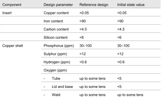
Table 15 shows the material compositions of the copper shell (the copper itself is not shown but is more than 99 % by mass) and of the insert.
Table 15: “Material composition at the initial state” (from Table 7-1 of SKB TR-10-14)
Component Design parameter Reference design Initial state value
Insert Copper content <0.05 <0.05
Iron content >90 >90 Carbon content <4.5 <4.5 Silicon content <6 <6 Copper shell Phosphorus (ppm) 30–100 30–100
Sulphur (ppm) <12 <12 Hydrogen (ppm) <0.6 <0.6 Oxygen (ppm)
- Tube up to some tens <5 - Lid and base up to some tens <5
- Weld up to some tens up to some tens
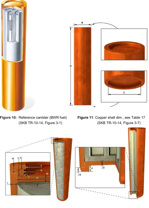
The reference canister for BWR fuel is shown in Figure 9 and Figure 10 (similar presentations of a PWR canister have not been found).
For the copper shell, Section 3.2.3 of TR-10-14 states: “The dimensions are given in the figures and tables below. All dimensions are specified at room temperature, 20°C.” The figures 3-3, 3-7, 3-8 and 3-9 correspond to figures 10-13 here. There is only one table (3-6) in TR-10-14 and it is quoted in Table 16 here.
“The dimensions of the cast iron insert with the steel lid are given in the figures and tables below. All dimensions are specified at room temperature, 20°C.” The quote is from Section 3.1.3 of TR-10-14 where the figures 3-4, 3-5 and 3-6 correspond to figures 14-16 here. Only a selection of TR-10-14 Table 7-3 data is quoted in Table 17 here (the tables referred to in the quote are not used).
Information on inserts provided in Table 3-3 and Table 3-5 of TR-10-14 (where a further reference to SKBdoc 1203875 is given) is merged into Table 18 here.
Figure 9: “Exploded view of the reference canister and its components (from the left: copper
base, copper tube, insert, steel lid for insert and copper lid)” (SKB TR-10-14, Figure 3-3).
Figure 10: Reference canister (BWR fuel) Figure 11: Copper shell dim., see Table 17
(SKB TR-10-14, Figure 3-1) (SKB TR-10-14, Figure 3-7)
Figure 12: Copper lid dim., see Table 17 Figure 13: Copper base dimensions, see Table 17
Table 16: “Dimensions for copper shell /SKBdoc 1203875/” (Table 3-6 in SKB TR-10-14).
Figure no and dimension designation
Designation Nominal value
(mm) Tolerance (mm) 11 A Total length 4,835 +3.25/–2.75 11 B Outer diameter 1,050 +1.2/–1.2 11 C Inner diameter 850 +0.8/–0.8 12 T Wall thickness Weld thickness* 49 48.5 +0.3/–0.3 +0.7/–0.7 12 E Inner diameter 952 +0.5/–0.5 12 F Inner diameter 821 +0/–0.5 12 G Inner diameter 850 +0.8/–0.8 12 H Diameter, lid 953 d8 12 H Diameter, tube 953 H8 12 I Corner radius 10 – 12 K Dimension 35 +0.5/–0.5 12 L Dimension 50 +0.2/–0.2 12 M Thickness, lid 50 +0.6/–0.6 12 N FSW position top 60 13 P Dimension 75 +0.3/–0.3 13 Q Thickness, base 50 +1/–1 13 R FSW position 50
Calculated Inner free length 4,575 +0.6/–0.1
Calculated Axial gap between steel and copper lids 2 +1.1/–0.3 Calculated Radial gap between shell and insert 1.5 +0.25/–0.5 * The weld thickness differs from the wall thickness since the copper tube surfaces that connect to the lid and base respectively are further machined.
Table 17: “Dimensions at initial state” (selection from Table 7-3 of SKB TR-10-14)
Component Design parameter Reference design
Initial state value Insert PWR Edge distance (mm) 37.3 ± 10 37.3 ± 5
C-C distance between compartments (mm)
370 ± 3.6 370 ± 3.62
Copper shell
Thickness (mm) All shell parts Fraction of canisters - Tube 49.0 Minimum > 47.5:
45–47.51:
Minimum < 451:
> 99%
Few per thousand Negligible - Lid and base 50.0
- Weld 48.5 - Local reduction due to defects - < 10 10–201 >201 > 99.9% one per thousand negligible
1 Values occurring only at disturbed operations considering both the manufacturing processes
and inspection
2 The initial state values are based on measures from the reference design
Figure 15: Insert (BWR) channel tubes with dimensions for PWR fuel, see Table 18
(SKB TR-10-14, Figure 3-5)
Figure 16: Steel lid dimensions, see Table 18
(SKB TR-10-14, Figure 3-6)
The inserts and the range of geometry variations that may be credible need to be specified and verified to an extent consistent with what will be credited for in the criticality safety assessment. SKB presents considerable information on this but the information is not complete and that is clarified in the documentation. Most of the verification and testing has involved BWR canisters with inserts. Figure 17 and Figure 18 show BWR canister inserts and some of the testing. Table 19 shows material checks while Table 20 shows measured dimensions for some PWR-inserts. Table 21 contains detailed information on the copper material used to form canister shells during 2005-2008.
Figure 17: Insert channel tube cassette (BWR) (SKB TR-10-14, Figure 5-4)
“Material properties for the insert steel lid are based on the steel S355J2G3” (Section 4.2.1 in TR-10-14).
Figure 18: “Testing areas for BWR insert. The areas investigated with the various methods are
angle scanning (lilac), normal scanning (green) and transmission testing (yellow)” (SKB TR-10-14, Figure 5-5)
Table 18: Dimensions for PWR-inserts.
Figure no and dimension designation
Designation Nominal value
(mm) Tolerance (mm) Insert dimensions 14 A Length of insert 4,573 +0/–0.5 14 D Insert diameter 949 +0.5/–0 Steel lids Weld thickness* 16 E Diameter 910 h7 16 F Lid thickness 50 +0.1/–0.1 16 G Bevel angle 5° +0.1°/–0.1° Inserts 14 B Thickness of bottom 80 +10.1/–5.6 14 C Interior length 4,443 +5/–10 15 H Edge distance 37.3 +10/–10
15 N Lifting eye holes Two holes with M45
PWR-Insert channel tubes
3-5 I Ext. channel tube corner radius 20 +5/–5
3-5 K Distance between channel tubes 110 +6.2/–6.2
3-5 J Calculated C-C distance between compartments 370 +3.6/–3.6 3-5 L Calculated Int. channel tube (before casting) 235×235 +5.1/–5.1*
3-5 M Channel tube thickness 12,5 +1.25/–1.25
3-5 Ext. channel tube cross section 260 +2.6/–2.6
* This tolerance of inner cross section of channel tube is valid before casting.
Insert dimensions
A selection of text from Section 7.1.2 of TR-10-14 follows: “The specified edge distance is 33.3 ± 10 mm, giving an acceptable minimum measure of the edge distance of 23.3 mm.” “The results from the test manufacturing” “shows that manufactured inserts conform to the specification (misalignment of 3–8 mm). When considering the actions recently performed to reduce the misalignment of the cassette and the ultrasonic measurement, the misalignment under normal production can be assumed to be ± 5 mm. The probability to exceed the specified ± 10 mm is regarded to be negligible”.
Concerning dimensions for the internal channel tube the following information is obtained from Table 4-8 of TR-10-14: The reference design internal channel tube cross section before casting is 235 mm × 235 mm. Gauge dimensions (used after casting) are 226 mm × 226 mm (preliminary data). Section 7.1.6 of TR-10-14 specifies that: ”So far, no verification of the C-C distance between compartments by physical measurement has been done on manufactured inserts.”
Section 5.2.10 of TR-10-14 presents some testing results for manufacturing: “The development of PWR inserts had until 2007 been carried out on a significantly
smaller scale. Subsequently, development has been intensified and, as a
consequence of the experience gained in the manufacturing of BWR inserts, good progress has been made.”
“The reported results are based on the five BWR inserts manufactured in 2007 and on the three PWR inserts manufactured with the channel tube dimension specified in the reference design.”
Information from the dimension inspection is presented in SKBdoc 1175208 (the Manufacturing Report). Section 5.2.10 of TR-10-14 has the following text: “For PWR inserts, problems have been experienced in gauging with a gauge measuring 226×226 mm in size. For example, only one of these three inserts has met the gauge values. During 2007, the technique of inserting compacted sand into the channels before casting was further developed. When an improved compaction of sand has been used, it has been possible for the channels to be gauged after casting. The problem is now deemed to have been solved, but further means for improvement will be tested.”
Table 19: “Three individually manufactured PWR inserts compared to the technical
specifications for test manufacturing” (from Table 5-1 of SKB TR-10-14) Material Material composition for nodular cast iron (%)
The content of Fe is above 90% in all inserts.
Cu C Si Mn P S Ni Mg Technical specification ≤ 0.05 3.2–4.0 1.5–2.8 0.05–1.0 ≤ 0.08 ≤ 0.02 ≤ 2.0 0.02–0.08 IP7 0.01 3.39 2.32 0.18 0.038 0.008 0.55 0.036 IP8 0.02 3.43 2.25 0.15 0.042 0.009 0.48 0.044 IP9 0.02 3.41 2.41 0.15 0.034 0.005 0.53 0.057 Mean value 0.017 3.41 2.33 0.16 0.038 0.007 0.52 0.046 Standard deviation 0.006 0.02 0.08 0.02 0.004 0.002 0.04 0.011
Table 20: “Recorded maximal deviation of edge distance in” “three PWR inserts” (from Table
5-4 of SKB TR-10-14)” Tolerance in edge distance – reference design (technical specification)
PWR inserts Maximum deviation from nominal edge distance (mm) ± 10 (± 5) IP7 5.5 IP8 4.0 IP9 2.9 Mean value 4.1 Standard deviation 1.3
Table 21: “Material composition (ppm) of copper ingots for copper tubes manufactured over the period 2005–2008. Contents are specified in ppm apart from the Cu content, which is
expressed as a percentage. To the right, the mean value (MV) and standard deviation (STD) have been compiled.” (Table 5-5 in SKB TR-10-14) Tube no: Specification Material composition – large ingot for tubes
T45 T46 T47 T48 T53 T56 T57 T58 MV STD Man. Year 2005 2005 2005 2005 2007 2007 2008 2008 Cu ≥99.99 99.99 99.991-99.992 99.99 99.99 99.991–99.992 99.991 99.991 99.992 99.991 0.001 P 30–100 71 67–70 66–72 66–72 60–73 67–72 69–88 54–56 68.4 7.8 O <5 0.8–1.1 0.7–0.9 0.8–1.2 0.8–1.5 1.0–1.8 0.9–1.3 0.5–0.7 1.6–2.4 1.13 0.49 S <8 4.8 4.7–4.8 4.5–4.8 4.4 5.3–5.7 4.3 4.3 5.3–5.6 4.77 0.47 H <0.6 0.3–0.4 0.3–0.4 0.4–0.5 0.3–0.5 0.4–0.6 0.43–0.44 0.28–0.5 <0.1 0.37 0.14 Ag <25 13 13.6–14.2 13.2–13.4 13.5 13.9-14.1 14.9 14.3-15 13.2 13.8 0.7 As <5 0.81 0.78–0.81 0.80–0.83 0.82 0.78 0.96–0.97 0.87-0.99 0.85-0.87 0.85 0.07 Bi <1 0.114–0.116 0.113-0.116 0.109-0.112 0.119-0.120 0.18-0.19 0.20-0.21 0.15-0.21 0.104-0.117 0.14 0.04 Cd <1 <0.003 <0.003 <0.003 <0.003 <0.003 <0.003 <0.003 <0.003 <0.003 – Fe <10 1.4 1.4–1.5 1.4 1.4–1.5 0.6–0.7 0.2–0.4 0.6–0.7 1.1–1.2 1.06 0.44 Mn <0.5 <0.1 <0.1 <0.1 <0.1 <0.1 <0.1 <0.1 <0.1 <0.1 – Ni <10 0.7–0.8 0.7–0.8 0.8–0.9 0.8–0.9 0.7–0.8 0.4 0.3–0.5 1.1–1.2 0.74 0.24 Pb <5 0.24 0.24–0.25 0.27 0.27-0.28 0.32 0.25-0.27 0.18-0.26 0.26-0.29 0.26 0.03 Sb <4 0.054–0.060 0.053 0.053-0.054 0.06 0.11 0.10-0.11 0.08-0.10 0.06 0.072 0.023 Se <3 0.2 0.2 <0.09 <0.09 0.3 0.4 0.3 0.1–0.2 0.22 0.11 Sn <2 0.05-0.06 0.05-0.06 0.05-0.06 0.06-0.07 0.09 0.1 0.06-0.07 0.18-0.19 0.084 0.043 Te <2 0.05 0.05 0.05 0.05 0.06 0.1 0.07–0.11 0.05 0.063 0.021 Zn <1 <0.1 <0.1 <0.1 <0.1 <0.1 <0.1 <0.1 <0.1 <0.1 –
6. Additional specifications in the SKB
criticality safety report
1
The criticality safety report in the SKB application documentation (SKBdoc
1193244) is reviewed separately from the basic technical documents. A purpose is to avoid using conservative or other assumptions in the criticality safety assessment to be mistaken for facts. Editorial mistakes may also have been introduced in SKBdoc 1193244. It is assumed here that the basic technical documents (e.g. 10-13, TR-10-14 and TR-10-52) are reviewed by more people than what is the case for SKBdoc 1193244 and that the quality control of specifications meets a higher standard. On the other hand, the conclusions of SKBdoc 1193244 are probably at least as reliable as the conclusions in other documentation that builds on SKBdoc 1193244. Some of the fuel and reactor operating data in TR-10-13 (the Spent fuel report), e.g. Table A-4 and loading curve information (e.g. Section 6.7), are taken from SKBdoc 1193244. That report also contains references to source documents. They may not be available for this review but the information on the sources are valuable.
Table 22 is taken from Appendix 3 in SKBdoc 1193244, which is assumed to be correct, except for some minor uncertainties (marked in red) and some editorial changes made (also marked in red text or as changes) by the author. Some of the specifications in Table 2 (from TR-10-13) are different to Table 22 specifications and may be more accurate since they are the results of checks. Editorial changes to Table 22 include a change of the fuel type “17x17 HTTP” to “17x17 HTP”and that the “17x17 HTP M5 Monobloc” fuel type is renamed to be the same as in Table A-4 of TR-10-13, i.e. “17x17 HTP X5”. Footnotes 2 and 4 contain minor editorial corrections made by the author.
Table 22: PWR fuel type specifications (basis for Table 2) (from Appendix 3 of SKBdoc 1193244).
Fuel type W15x15 KWU15x15 F15x15
AFA3G 15x15 AGORA W17x17 AA17x17 F17x17 S17x17 HTP 17x17 HTP 17x17 HTP M5 17x17 HTP X5 17x17 AFA3G
Table footnote reference 1 1 2 3 1 1 9 4 5 6 7 10
No of fuel rods 204 204 204 204 264 264 264 264 264 264 264 264
Fuel rod pitch (mm) 14.3 14.3 14.3 14.3 12.6 12.6 12.6 12.6 12.6 12.6 12.6 12.6
Fuel rod outer diameter (mm) 10.72 10.75 10.72 10.77 9.5 9.5 9.5 9.55 9.55 9.5 9.5 9.5
Fuel rod inner diameter (mm) 9.48 9.3 9.484 9.505 8.36 8.36 8.36 8.33 8.33 8.36 8.36 8.36
Cladding thickness (mm) 0.62 0.725 0.618 0.6325 0.57 0.57 0.57 0.61 0.61 0.57 0.57 0.57
Pellet diameter (mm) 9.29 9.11 9.294 9.33 8.19 8.19 8.19 8.17 8.165 8.192 8.192 8.192
Cladding material Zr4 Zr4 M5 Zr4 Zr4 Zr4 Zr4 Zr4 Zr4 M5 M5 Zr4
Active fuel length (mm) 3658 3658 3658 3658 3658 3658 3658 3658 3658 3658 3658 3658
UO2 density (g/cc)* 10.22 10.46 10.52 10.52 10.45 10.45 10.45 10.45 10.45 10.52 10.55 10.52
No of guide tubes 20 20 20 20 24 24 24 24 24 24 24 24
Guide tube material Zr4 Zr4 M5 M5 Zr4 Zr4 Zr4 PCAm PCAm PCAm PCAm Zr4
Guide tube outer diameter (mm) 13.87 13.86 14.1 14.1 12.24 12.09 12.05 12.24 12.24 12.24 12.45 12.45 Guide tube inner diameter (mm) 13.01 13 13.05 13.05 11.44 11.18 11.25 11.3 11.3 11.3 11.45 11.45 Guide tube cladding thickness (mm) 0.43 0.43 0.525 0.525 0.4 0.455 0.4 0.47 0.47 0.47 0.05 0.5
No of instrument tubes 1 1 1 1 1 1 1 1 1 1 1
Instrument tube material Zr4 Zr4 M5 M5 Zr4 Zr4 Zr4 PCAm PCAm PCAm PCAm Zr4
Instrument tube outer diameter (mm) 13.87 13.86 14.1 14.1 12.24 12.09 12.05 12.24 12.24 12.24 12.45 12.45 Instrument tube inner diameter (mm) 13.01 13.03 13.05 13.05 11.428 11.428 11.25 11.3 11.3 11.3 11.45 11.45 Instrument tube cladding thickness (mm) 0.43 0.43 0.525 0.525 0.406 0.406 0.4 0.47 0.47 0.47 0.5 0.5
1. CLAB 96 - Dataunderlag för kriticitetsberäkningar, Agrenius Ingenjörsbyrå AB, augusti 1991
3. Areva A1C-1332397-0 NP fuel assemblies delivered to Ringhals 2/31/07 4. Fuel type data for final storage - PWR - Siemens HTP Ringhals 3 2000-06-16
5. Areva A1C-1313665-4 Reprocessing information for Framatom ANP fuel assemblies delivered to delivered to Ringhals 3/4 6. Areva A1C-1333871-0 NP fuel assemblies delivered to RH 3/25/08
7. Areva A1C-133864-0 NP fuel assemblies delivered to RH 3/24/07 8. Fuel type data for final storage - PWR - reload 18 / SUPW Ringhals 4
9. ABB BR 91-446 Criticality calculations: PWR Compact canisters (Clab 96), 1991-10-28 10. Fuel Type Data for Final Storage - PWR - Reload 18 / SUPW Ringhals 4 17x17AFA3
SKBdoc 1193244 refers to a reference /7/ (ORNL/TM – 1999/99) where the results show that the predicted keff value increases if lower specific power is used. SKB
used “a relatively low power density of 14 MW/assembly” (slightly different to the 15 MW/assembly specified in Table 7 of the same report and shown in Table 23 below). This is compared to the Ringhals 2 value which in average is 17 MW/assembly and to the Ringhals 3/4 value 18 MW/assembly which will be increased to 20 MW/assembly.
Some PWR-fuel assemblies contain integral burnable poison. The SKBdoc 1193244 refers to another reference /8/ (NUREG/CR-6760) that shows that keff for fuel
containing Gd2O3 is always lower than the multiplication factor for fuel without
Gd2O3 throughout burnup. Burnable poison was thus not modelled in the SKB
criticality safety assessment.
In order to calculate the isotopic composition of the fuel at different burnup the fuel had to be subjected to different burnup histories. The main parameters for the depletion calculations are shown in table 23.
The burnup of a fuel assembly is always the assembly average burnup if nothing else is stated.
Table 23: “Main parameters for the depletion calculation” (from Table 7 of SKBdoc 1193244)
Parameter PWR
Assembly power (MW) 15 Avg. fuel temperature (°C) 625 Coolant pressure (bar) 155 Coolant temperature (°C) 304 Boron concentration (ppm) 600 Coolant density (kg/dm3) 0.68 Cycle length (days ) 345 Shutdown length (days) 20
Decay time (yrs) 1
(Sources: Ringhals 2007-10-19, 1960160/1.1 and OKG 2008-05-26, reg nr 2008-14670. Confidential information. Available only for the Swedish Radiation Safety Authority.)
In initial PWR-cores in Ringhals burnable poison rods were used in about 60 of the 157 fuel assemblies. The poison rods are made of stainless steel, borosilicate glass and zircaloy. The SKBdoc 1193244 refers to yet another reference /9/ (NUREG/CR-6761) that shows that the presence of burnable poison rods gives a higher keff
compared with fuel without poison rods throughout burnup (after removal of those rods). The burnable poison is depleted during the first cycle. If the burnable rod cluster is not removed after the first cycle a significant portion of the reactivity difference is shown to be due to the displacement of moderator. The reactivity difference is shown to be up to 3% Δk. This has to be considered when fuel assemblies that have contained burnable poison rods will be compared with the loading curve.
In addition to the above given information, the following quotes are selected from SKBdoc1193244 for being of major interest:
“Normally during operation control rods in both BWR and PWR are not inserted in the core. The effect of inserted control rods has therefore not been evaluated.” (Section 9.9 of SKBdoc1193244)
“The declared assembly average burnup is based on the plant heat balance, measurements and calculations of the power distribution in the core. Based on uncertainties of the measurements and calculations the uncertainty in the burnup prediction is estimated to be within σBU=2% for BWR and 2σBU=3.65% for
PWR. (Sources: OKG 2008-05-26, reg nr 2008-14670 and Ringhals 2007-10-19, 1960160/1.1. Confidential information. Available only for the Swedish Radiation Safety Authority.)” (Section 9.5 of SKBdoc1193244)
“Due to the higher temperature and lower moderator density in the top of the core more Pu-239 will be produced than in average” (Section 9.6). In SKBdoc 1193244 (Section 9.6) the core exit temperature and the corresponding water density was used (for PWR).
The “axial burnup distributions from 15 cores from Ringhals 2, 3 and 4 were studied. In addition 9 cores from the Great- and Frej-projects were studied, see appendix 4. The fuel types are 15x15 and 17x17-fuel with burnup from 10 MWd/kgU up to 65 MWd/kgU. Initial enrichments are 3.2 – 4.95% U-235. From this population a number of distributions were chosen for analysis.
Distributions with the highest and lowest peaking factors (F), with the lowest burnup in the bottom node, with the lowest burnup in the top node were selected. A
bounding burnup distribution was constructed by reducing the burnup in the bottom and top node by 20% while keeping the assembly burnup constant. The resulting distributions are shown in figure” 19 (Section 9.8 of SKBdoc1193244).
Figure 19: PWR axial burnup distributions (SKBdoc 1193244, Figure 18)
“It should be noted that the radial difference in the burnup from the average is ± 10% in the calculations which is higher than values reported in sources: Ringhals