http://www.diva-portal.org
Postprint
This is the accepted version of a paper published in Electrochimica Acta. This paper has been peer-reviewed but does not include the final publisher proof-corrections or journal pagination.
Citation for the original published paper (version of record):
Eslami, M., Fedel, M., Speranza, G., Deflorian, F., Andersson, N-E. et al. (2017)
Study of selective deposition mechanism of cerium-based conversion coating on Rheo-HPDC aluminium-silicon alloys.
Electrochimica Acta, 255: 449-462
https://doi.org/10.1016/j.electacta.2017.09.182
Access to the published version may require subscription. N.B. When citing this work, cite the original published paper.
Permanent link to this version:
1
Study of selective deposition mechanism of cerium-based conversion coating
on Rheo-HPDC aluminium-silicon alloys
1. Maryam Eslami (Corresponding author)a Department of Industrial Engineering, University of Trento, Via Sommarive 9, 38123 Povo (TN), Trento, Italy Email: maryam.eslami@unitn.it, Tel: +39-3899121304, Fax: +39-0461281977
2. Michele Fedel
a Department of Industrial Engineering, University of Trento, Via Sommarive 9, 38123 Povo (TN), Trento, Italy Email: michele.fedel@unitn.it
3. Giorgio Speranza
b Center for Materials and Microsystems, Bruno Kessler Foundation (FBK), Via Sommarive 18, 38123 Povo (TN), Trento, Italy, Email: speranza@fbk.eu
4. Flavio Deflorian
a Department of Industrial Engineering, University of Trento, Via Sommarive 9, 38123 Povo (TN), Trento, Italy Email: flavio.deflorian@unitn.it
5. Nils-Eric Andersson
c Department of Materials and Manufacturing, School of Engineering, Jönköping University, Gjuterigatan 5, Box 1026, 55111, Jönköping, Sweden, Email: nils-eric.andersson@ju.se
6. Caterina Zanella
c Department of Materials and Manufacturing, School of Engineering, Jönköping University, Gjuterigatan 5, Box 1026, 55111, Jönköping, Sweden, Email: caterina.zanella@ju.se
_________________________________________________________________________________________________________________________________
Abstract
Cerium-based conversion coatings were deposited on Rheo-High Pressure Die Cast (HPDC) Al-Si alloys by immersion in cerium nitrate aqueous solutions. Rheocast Al-Al-Si alloys have a heterogeneous microstructure and present a challenge for the conversion treatment. Different parameters were studied to optimize the conversion coating, and NaCl or H2O2 were also added to the solution to modify or accelerate the deposition process. The mechanism of the coating formation was studied by means of focused ion beam milling (FIB) assisted SEM. The results show that applying cerium-based conversion coating to Al-Si alloys, is possible and a preferential deposition is obtained due to the presence of iron-rich intermetallic particles inside the eutectic region. The formation mechanism of selectively deposited cerium-based conversion coating
2 includes dissolution of aluminium matrix, selective dissolution of aluminium from the noble intermetallic particles, oxidation of iron from the intermetallic particles, and the deposition of cerium hydroxide/oxide layer. The results reveal that the improvement in corrosion resistance in the presence of selectively deposited cerium-based conversion coating is more significant compared to the homogenous coating deposited from the conversion solution containing H2O2.
Keywords: Cerium-based conversion coating; Al-Si alloy; Rheo-HPDC; Corrosion
_________________________________________________________________________________________________________________________________
1. Introduction
Conversion coatings are oxide-based coatings which have been utilized to replace the native oxide film on a metal surface such as aluminium, zinc, or magnesium to provide higher corrosion resistance [1]. For many decades, chromium-based conversion coating (CrCC) has been used due to its extensive corrosion protection, especially for aluminum alloys. However, concerns and new restrictions about the environmental hazards of chromium compounds [2] have led to intensive efforts to develop alternative pretreatments [3].
Corrosion inhibitive effect of rare earth metal salts for aluminium alloys was first discovered by Hinton et al. back in the 1980s [4]. These salts were found to be non-toxic, relatively cheap, and abundant [5]. Not only pioneer studies [5], but recent ones [6] have also emphasized that cerium-based salts and subsequently cerium-cerium-based conversion coatings (CeCC) are the most effective in the sense of corrosion inhibition over other lanthanide-based conversion coatings. CeCC was also shown to possess self-healing properties under specific conditions [7], a feature which is the unique for CrCC.
Cerium-based conversion coatings consist of a combination of Ce (III) and Ce (IV) hydroxide/oxide layers [8, 9] formed on the metal surface due to the metal electrochemical activity.
3 Sharing the same common characteristics, cerium-based conversion layers exhibit morphologies and compositions, which are specific to the substrate composition and microstructure [10]. A local pH increase due to the cathodic activities, such as oxygen or hydrogen peroxide reduction reactions (in H2O2 containing solutions) can result in cerium hydroxide/oxide precipitation:
O2+2H2O+4e- → 4OH- (1)
H2O2 +2e-→ 2OH- (2)
Ce3++3OH- → Ce(OH)3 (3)
4Ce3++ O2+4OH-+2H2O → 4Ce(OH)22+ (4)
Ce(OH)22++2OH-→ Ce(OH)4 → CeO2+2H2O (5)
The cathodic reactions occur over the phases with higher potential with respect to the aluminium matrix, therefore the role of these phases (for instance intermetallic (IM) particles) and their influences on CeCC are worth to be investigated. There are many papers supporting the idea that the deposition of cerium-based compounds starts locally on the cathodic IM particles [11-13] while the lateral growth of the coating and the integration of small precipitations lead to the covering of the whole surface [4, 8].
Researches on the formation mechanism of CeCC have been mainly focused on alloys for aerospace applications such as AA2024 [8, 9, 11-28] and AA7075 [19, 29-36]. In these alloys the role of copper-rich and other noble IM particles on the deposition of cerium-based layers has been widely studied [11-13, 27, 28]. Most of the IM particles in copper containing alloys are cathodic with respect to the aluminium matrix (such as AlFeMnCu). However, anodic particles such as Al2CuMg (S-phase) also participate in the deposition mechanism after dealloying (selective dissolution of magnesium and aluminium) making them nobler compared to the aluminium matrix
4 [13, 27]. A further model [27] states that even a small dissolution of magnesium and the consequent hydrogen evolution can locally increase the pH high enough for cerium hydroxide/oxide precipitation. In this way, precipitation of cerium-based compounds on the IM particle can happen even before it becomes cathodic. Other studies [13] showed that copper dissolution from S-phase during the deposition of the conversion coating and the further cathodic reduction of copper ions on the matrix result in the formation of copper islands. This phenomenon promotes more dissolution of surrounding aluminium matrix leading to areas of major oxide growth. Interestingly, the composition of cerium layer differs from CeO2 on more active cathodic IM particles (AlCuFeMn) to Ce(O2)(OH)2 over the aluminium matrix. The oxide layer over S-phase changes from aluminium oxide to an aluminium oxide containing copper oxide and cerium oxide [13].
The study by Hughes et al. [14] on the formation kinetics of cerium hydroxide/oxide layer on AA2024 showed that the coating deposition occurs in two stages involving induction and deposition. Induction step was found to involve the deposition of cerium-based compounds over the cathodic IM particles together with aluminium oxide growth while the deposition step involves deposition of cerium-based compounds over the surface.
Despite many researches on the formation of CeCC on different aluminium alloys, only a few works [37-39] have been reported on the formation of CeCCs on cast Al-Si alloys.
High Pressure Die Casting is a commonly used casting process for the majority of light alloy components [40, 41]. Recently, this process has been integrated with semi-solid metal processing such as rheo-casting to introduce a new casting technology (called Rheo-HPDC) for producing high-quality components with sound microstructure [41-44]. Rheo-HPDC widens the composition range of castable alloys, but unfortunately, it also increases the inhomogeneity of the microstructure in the final component in comparison to the conventional HPDC process [45].
5 Previous studies showed that this microstructural inhomogeneity together with the presence of the eutectic silicon phase and iron-rich IM particles can result in pitting corrosion in chloride containing environments which differs in various positions of the component [46]. It can be expected that the complexity of the microstructure in Rheo-HPDC aluminium alloys can influence the formation of CeCCs.
This paper focuses on the formation mechanism and characterization of CeCC on Rheo-HPDC low silicon content aluminium alloys. Focused Ion Beam milling-Scanning Electron Microscope (FIB-SEM) is an adequate tool to study the substrate and surface features beneath the CeCC. This method has also been used by other researchers such as Pinc et al. [22] to study the formation of subsurface crevices during the cerium conversion process. Electrochemical impedance spectroscopy (EIS) and potentiodynamic polarization were applied to investigate the electrochemical behavior of CeCCs. Two Al-Si alloys with 2.5 and 4.5 wt.% silicon were chosen to be treated by the conversion treatment in order to examine the effect of silicon content on the process. The pretreatment optimization was obtained by investigating the effect of varying the coating process parameters such as immersion time, concentration of cerium ions, chloride ions, and hydrogen peroxide on the deposition and the corrosion resistance of CeCCs.
2. Experimental
2.1. Rheo-HPDC process
Components of two Al-Si alloys with the measured compositions of (wt.%) Si: 2.41, Fe: 0.46, Cu: 0.13, Mn: 0.02, Mg: 0.58, Zn: 0.04, Al: balance (2R) and Si: 4.5, Fe: 0.48, Cu: 0.13, Mn: 0.02, Mg: 0.58, Zn: 0.04, Al: balance (4R), were produced using a 400 tons HPDC machine that was equipped with an automated RheoMetalTM slurry generator. RheoMetalTM exploits an Enthalpy Exchange Material (EEM) as an internal cooling agent to generate the slurry. The die utilized
6 included two halves: a fixed and a moving half. The temperature of the fixed half was set between 230-250 °C while the temperature of the moving half was set between 280-320°C. The holding furnace temperature was fixed at 675 °C. The shot weight was approximately 5 kg and ladling was performed using a standard cast iron ladle to which the EEM was added (5-6 % of the shot weight). The stirring rate used was 900 rpm and the slurry solid fraction was about 40 %. The final slurry temperature was then set at 610 ± 1 °C. The die cavity fill-time was 31 ms while the first stage and the second stage piston speed were 0.23 and 5.2 m/s, respectively. These conditions were similar to standard settings for this type of component under normal HPDC processing. The studied component is an experimental cavity filter demonstrator resembling the real component used in telecom base stations. We have studied the microstructural and electrochemical features of these Al-Si alloy components in our previous work [46].
2.2. Cerium conversion process
Samples of the two alloys were cut into pieces of 1cm×1cm and ground using SiC abrasive papers of P1200 and P4000. These samples were then rinsed and ultrasonically cleaned in acetone for 10 minutes. The alkaline activation step included etching in 40 g/l NaOH solution for 15 seconds. Between each of these steps, samples were rinsed with deionized water and then dried. Conversion solutions were made from analytical grade hydrated cerium nitride (Ce(NO3)3.6H2O), sodium chloride (NaCl), and hydrogen peroxide (H2O2). Before immersion of the samples, all the solutions were aged for at least 30 minutes so that the cerium species reached the equilibrium. Details of the solutions chemistry and immersion times are presented in Table. 1. Conversion
7 treated samples were then dried and kept in a desiccator for further microstructural and electrochemical testing.
Table. 1. Details of conversion process parameters
2.3. Layers characterization
Microstructural features of the cerium-based conversion coatings were examined by Scanning Electron Microscopy (SEM, JSM-IT300), under high vacuum conditions with 20 kV beam energy. Energy-dispersive X-ray spectroscopy (EDXS) was exploited to measure the composition of the conversion layers and to collect the elemental map of Al, Si, Fe, Ce and O. A LYRA3 FIB/SEM was used for cross sectioning and analysis of the treated surfaces. The FIB milling conditions were as follows: 30kV, 5nA for rough milling and 1 nA for final polishing. In this case, beam energy of 15 kV was employed. For EDXS analysis 254 frames mapping and 50 µs dwell time were utilized. The surface state of conversion treated samples were analysed using X-ray photoemission spectroscopy (XPS). The analysis was carried out using an Axis DLD Ultra instrument (Kratos– Manchester UK). Acquisitions were composed by wide scans on a binding energy range of 1250 – -5 eV using a 160 eV pass energy. High-resolution core line spectra was performed by setting the analyser pass energy at 20 eV and the energy step at 0.05 eV. When necessary, charge compensation was utilized on samples with scarce conductivity. Compensation was optimized by
Investigated parameter Substrate Ce(NO3)3.6H2O (mol/l)
NaCl (mol/l) H2O2 (mol/l) Immersion time (h)
Concentration of Ce(NO3)3 2R, 4R 0.01, 0.05, 0.1 0 0 18 Concentration of NaCl 2R, 4R 0.05 0.01, 0.05, 0.1 0 18 Addition of H2O2/immersion time 2R 0.05 0 0.02 0.3 (20 m),1 Addition of H2O2/immersion time 4R 0.05 0 0.01, 0.02 0.3 (20 m),1
Addition of H2O2 and NaCl /immersion time
2R 0.05 0.05 0.02 0.3 (20 m),1
Addition of H2O2 and NaCl /immersion time
8 maximizing the peak intensity and minimizing the peak full width at half maximum of the main core line peaks. C 1s from contaminants at 285 eV was selected as a reference for energy scale alignment. The final energy resolution was ~ 0.35 eV. The analysis of the XPS spectra was performed using a home-made software based on the R platform. Care was taken when selecting the appropriate background subtraction and Gaussian components for peak fitting.
The electrochemical behavior and the corrosion resistance of CeCC treated Al-Si alloys were examined in a 0.05 mol/l NaCl solution by potentiodynamic polarization and electrochemical impedance spectroscopy (EIS). A traditional three electrode cell was exploited including the sample as the working electrode (with the exposure area of 1cm2), a platinum electrode as the counter electrode and a silver/silver chloride electrode (Ag/AgCl 3M KCl (0.210 V vs NHE) as the reference electrode. All the electrochemical tests were monitored by a computer-controlled potentiostat (Metrohm Autolab PGSTAT302N). In the polarization test, the sweep rate of 0.166 mV/s and the initial delay of 10 minutes were set. Cathodic and anodic branches were collected separately, starting from the open circuit potential (OCP) in both cases. Anodic and cathodic polarizations were stopped after the maximum current densities of 9×10⁻⁴ A/cm2 and 4×10⁻⁵ A/cm2 were reached, respectively. In the EIS tests, frequency ranged from 100 kHz to 10 mHz with 36 points/decade and the amplitude of the sinusoidal potential signal was 10 mV with respect to the OCP. To guarantee the reliability of the data, the electrochemical tests were repeated at least three times. Moreover, to compare the results, all the electrochemical tests were also conducted on bare 2R and 4R alloys.
9
3. Results and discussion
3.1. Morphology and composition
4.
Fig. 1. SEM-BS images of alloy (a) 2R and (b) 4R.
Fig. 1 depicts the microstructure of two Al-Si alloys substrates processed using Rheo-HPDC method. As it can be seen in these images, the microstructure of semi-solid cast Al-Si alloy contains primary α-Al particles in two different sizes, Al-Si eutectic dual phase region, and iron-rich needle shape intermetallic particles (β-AlFeSi). SEM image at higher magnification (Fig. 1 (b)) shows that the location of the intermetallic particles is mainly the eutectic region. Formation of two different range sizes of α-Al phase is attributed to the two-stage solidification in the semi-solid metal process. The formation of coarser α-Al particles (α1-Al) is related to the nucleation during slurry preparation, while finer particles (α2-Al) are formed during the second solidification stage inside the cavity with high cooling rate and the absence of shear force [47].
Fig. 2 shows the primary conversion coatings deposited from solutions of different Ce(NO3)3 concentrations on the alloy with 2.5 wt.% Si.
10
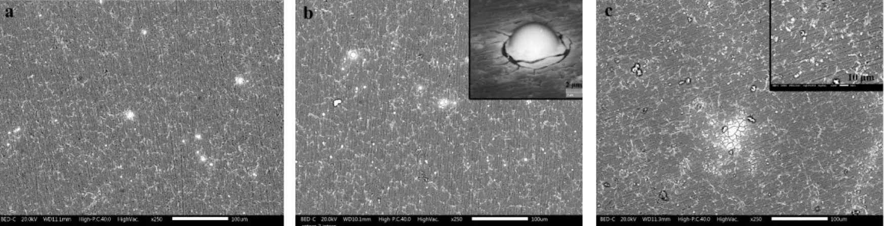
Fig. 2. SEM-BS images of 2R alloy treated using the solution of (a) 0.01 mol/l Ce(NO3)3, (b) 0.05 mol/l Ce(NO3)3, and (c) 0.1 mol/l Ce(NO3)3 for 18 hours.
According to the images in Fig. 2, cerium hydroxide/oxide deposition (white islands in the backscattered SEM images) is or has been started locally. It can be observed that the amount of cerium-based precipitates is higher on the eutectic region and/or the iron-rich IM particles inside them. The deposition of the conversion layer increases as the concentration of Ce(NO3)3 increases. It is noticeable that the background matrix of the conversion coating is less visible in the case of samples treated using the solutions of 0.01 and 0.05 mol/l Ce(NO3)3, while in the sample immersed in the solution of 0.1 mol/l Ce(NO3)3, the presence of background matrix is easily detectable, especially due to its cracked structure.
According to the literature [4, 8], this means that the deposition of cerium hydroxide/oxide layer starts from the cathodic sites but it grows further to cover the entire aluminium alloy surface [12]. In Fig. 2 (b), SEM image from a cerium-based nuclei at a higher magnification shows this lateral growth.
Higher Ce(NO3)3 concentration provides more cerium ions required for the precipitation since their numbers are reduced due to the formation of stable cerium nitrate complexes such as Ce(NO3)52–
11 and Ce(NO3)63– [48]. These stable complexes result from the oxygen-donor ligand and cerium cation interactions [49].
In these series of treated substrates, no significant difference can be observed on the degree of cerium deposition over α1-Al and α2-Al particles. As expected, not all eutectic region are covered by the CeCC and therefore not all of them were cathodically activated.
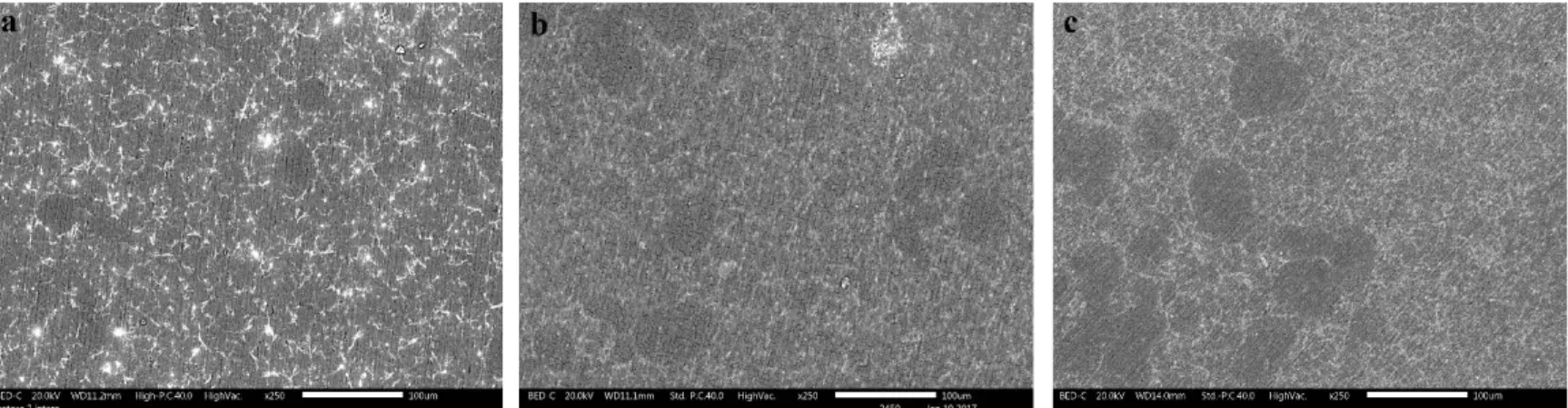
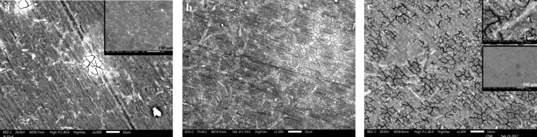
Fig. 3. SEM-BS images of 2R alloy treated using the solution of (a) 0.05 mol/l Ce(NO3)3 and 0.1 mol/l NaCl for 18 hours, (b) 0.05 mol/l Ce(NO3)3 and 0.02 mol/l H2O2 for 1 hour, and (c) 0.05
mol/l Ce(NO3)3, 0.05 mol/l NaCl and 0.02 mol/l H2O2 for 1 hour.
The effect of the addition of chloride ions and/or hydrogen peroxide to the solution on the morphology of the CeCC layers on 2R alloy is presented in SEM images of Fig. 3. Considering Fig. 3 (a), with 0.1 mol/l NaCl higher amount of cerium compounds depositions is observed. This coating shows some differences in comparison to the coating deposited from the same solution without NaCl (Fig. 2(b)). In presence of NaCl, the primary α-Al particles (α1-Al) show less coverage of CeCC (or a thinner layer) on their surfaces compared to α2-Al particles or compared to the samples treated using solutions without NaCl. SEM image of this coating at a higher magnification and the results of EDXS analysis confirm this phenomenon (Fig. 4).
12
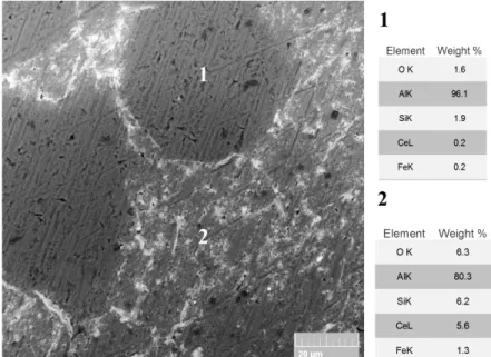
Fig. 4. SEM-BS image and results of EDXS analysis of 2R alloy treated using the solution of
0.05 mol/l Ce(NO3)3 and 0.1 mol/l NaCl for 18 hours.
Chloride ions in the conversion solution have an accelerating effect on the precipitation of cerium hydroxide/oxide layer. They can break the native aluminium oxide layer on the alloy surface and accelerate and activate the corrosion reactions (anodic and cathodic) on the micro-galvanic couples, formed in the eutectic regions [46]. In fact, they are adsorbed selectively on the crystal lattice of the aluminium oxide film and make complexation with Al3+ hydrate ions. This reaction leads to surface activation, an unstable film, and formation of local defects [50]. This leads to a higher pH and therefore more cerium hydroxide deposition [33, 51]. Nitride ions are not able to breakdown the aluminium oxide layer and they also passivate the surface of aluminium alloys by incorporating into the oxide [22, 52, 53]. Therefore, a faster deposition is expected in the presence of chloride ions compared to the plain cerium nitride solution.
Moreover, the activating effect of the chloride ions highlights the difference between the two different α-Al phases. α1-Al particles are less covered compared to α2-Al particles, resulting in heterogeneous deposition of the conversion layer due to the different levels of cathodic activity.
13 The results of WDS analysis of these grains show that they differ in the silicon content in the solid solution of aluminium: α2-Al grains contain higher silicon in comparison to α1-Al ones [47]. The higher level of silicon in the α2-Al phase contributes to increase its potential toward more cathodic values [54]. Moreover, the size of the grains makes the α2-Al grains closer and more interacting with the eutectic silicon phase and the iron-rich IM particles and therefore easier to be covered. The presence of chloride ions in the conversion solution can also affect the valence state of cerium. The equilibrium potential of oxidation reaction of Ce (III) to Ce (IV) is sensitive to the anions present in the solution:
Ce3++2H
2O ↔ Ce(OH)22++2H++e- (6)
The chloride ions decrease the equilibrium potential by 400 mV allowing the oxidation reaction to take place more easily [49].
Hydrogen peroxide can be added to the conversion solution to act as an oxidizing agent and therefore to have a more homogenous deposit. The presence of hydrogen peroxide, either alone or together with chloride ions increases the deposition rate and the thickness of the conversion layer, resulting in the formation of a conversion layer with cracked-mud structure (Figs. 3 (b) and (c)). This feature is due to the stresses induced in the coating during the drying step [11]. By adding hydrogen peroxide, the entire surface is covered by the conversion layer. However, some heterogeneities are still visible on the coating surface in which α1-Al particles are covered by a thinner deposit.
In the deposition of cerium-based conversion layer hydrogen peroxide acts as a complexing agent, an oxidant, a crystallization inhibitor, and a source of OH- ions [55]. Reduction of hydrogen
14 peroxide on the cathodic areas provides a source of hydroxyl ions (Reaction 2). Hydrogen peroxide also oxidizes Ce3+ ions to Ce4+ by the formation of a complex [55, 56]:
2Ce3+ +H2O2+2OH- ↔ 2Ce(OH)22+ (7)
The literature reports that these conditions lead to the formation of a cerium hydroxide/oxide coating containing mainly Ce (IV) species [55, 56].
Fig. 5. SEM-BS images of 4R alloy treated using the solution of (a) 0.05 mol/l Ce(NO3)3 and 0.1 mol/l NaCl for 18 hours, (b) 0.05 mol/l Ce(NO3)3 and 0.02 mol/l H2O2 for 1 hour, and (c) 0.05
mol/l Ce(NO3)3, 0.05 mol/l NaCl and 0.02 mol/l H2O2 for 1 hour.
The conversion layers deposited on 4R alloy from the solutions containing chloride ions (Fig. 5 (a)), hydrogen peroxide (Fig. 5 (b)), and chloride ions together with hydrogen peroxide(Fig. 5(c)), have similar characteristics to those on 2R alloy. The heterogeneity related to the thinner deposition over α1-Al particles is detectable especially in the conversion coating deposited from the solution of 0.05 mol/l Ce(NO3)3 and 0.1 mol/l NaCl (Fig. 5 (a)). The addition of hydrogen peroxide leads to the formation of a thick cracked coating all over the surface (Figs. 5 (b) and (c)). This coating is also heterogeneous in some parts as it can be seen in Fig. 5 (b). The surface
15 morphology of the cerium-based layer deposited from a combination of cerium ions, chloride ions, and hydrogen peroxide, contains cerium-rich nodules over the cracked background matrix.
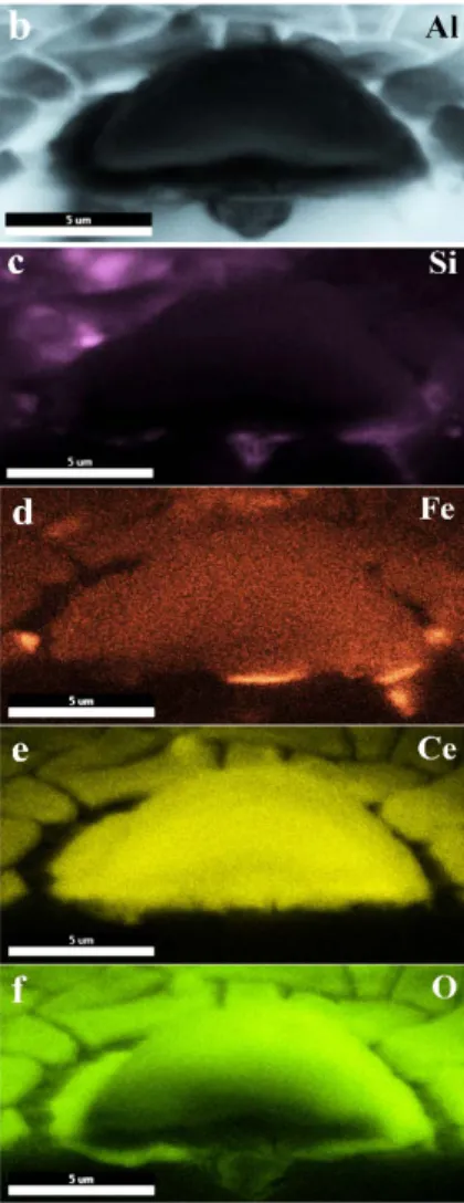
Fig. 6. (a) SEM-BS image and (b), (c), (d), (e) and (f) the elemental mapping of cross-sectional
view of 2R alloy treated using the solution of 0.05 mol/l Ce(NO3)3 for 18 hours.
Understanding the formation mechanism of the cerium-based conversion layer is possible by looking at the cross-sectional view of the local cerium-based precipitates. Fig. 6 provides this view for the conversion coating on 2R alloy, immersed in the solution of 0.05 mol/l Ce(NO3)3 for 18 hours. The elemental maps of Al, Si, Fe, Ce, and O are also provided in this figure. These images depict the presence of an iron-rich IM particle located inside the eutectic region, which is
16 detectable through the elemental map of Si (Fig. 6 (c)). It can be observed that the formation of the cerium-based layer started from the iron-rich IM particle. In addition, a cavity is visible under the cerium-based nuclei where the IM particle is located. The presence of this cavity is due to the corrosion process and is the result of the dissolution of aluminium phase in the eutectic region. It is worth mentioning that many cerium-based precipitates were checked and a cavity was always seen underneath each of them. According to the elemental map of O (Fig. 6 (f)), there is also oxide inside the cavity.
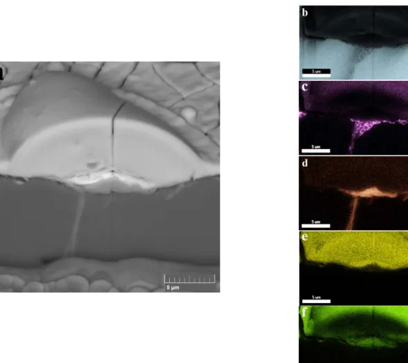
Fig. 7. (a) SEM-BS image and (b), (c), (d), (e) and (f) the elemental mapping of cross-sectional
view of 2R alloy treated using the solution of 0.05 mol/l Ce(NO3)3 and 0.1 mol/l NaCl for 18 hours.
17 SEM image and the elemental maps from the cross-sectional view of a cerium-based nuclei on 2R alloy treated in the solution of 0.05 mol/l Ce(NO3)3 and 0.1 mol/l NaCl for 18 hours are depicted in Fig. 7. The interesting phenomenon captured in this image is the oxidation of the IM particle, which can be seen through the oxygen mapping in Fig. 7 (f). The oxide seems to fill the cavity that was formed in the previous step. In the presence of chloride ions in the conversion solution, anodic and cathodic reactions are promoted and accelerated. After dissolution of aluminium from the aluminium phase, another process that can occur is the selective dissolution of aluminium from the IM particle that makes it richer in iron and silicon [57].
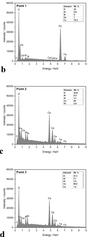
Considering the OCP of this system (⁓-0.6 V), pH of the solution (4.4), and according to Pourbaix diagram of iron [58], oxidation of iron is not thermodynamically possible. However, cathodic reactions increase the pH locally high enough for the possible formation of iron oxide, when the entire aluminium phase has been dissolved. Moreover, silicon does not seem to be participating in the oxidation process as no silicon is detected in the oxide. The extension of iron oxidation is visible in the SEM image and EDXS results taken after removing the conversion layer as shown in Fig. 8. Upon oxidation of iron, the particle becomes more cathodic [57], therefore, more suitable for the cathodic reactions.
18
Fig. 8. (a) SEM-BS image of underneath a cerium-based nuclei (the sample treated using the
solution of 0.05 mol/l Ce(NO3)3 and 0.1 mol/l NaCl for 18 hours), (b), (c), and (d) EDXS results from different points in the SEM image.
19 The very first layer of the cerium-based nuclei seems to be richer in cerium compounds as it appears whiter in the backscattered image (Fig. 7 (a)). The rest of the coating can be assumed to be a mixture of cerium hydroxide/oxide and aluminium oxide
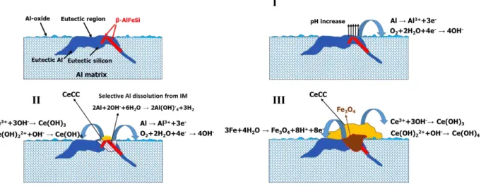
Fig. 9. Formation mechanism of the cerium-based conversion coating.
Fig. 9 presents the proposed formation mechanism of the cerium-based conversion layer. The presence of iron-rich IM particles is the main reason of the deposition of the conversion layer on the Al-Si alloy. According to our results, the formation mechanism can include three steps:
1. Dissolution of aluminium phase next to an iron-rich IM particle until there is no connection between the IM particle and the aluminium matrix. The cathodic reactions are localized on the IM raising the pH and triggering the cerium hydroxide/oxide deposition.
2. Selective dissolution of aluminium from the IM particle and then oxidation of the remained iron. The dissolution of aluminium from the iron-rich IM particle can occur according to the following reaction [59]:
20 The iron oxide fills the cavity that was formed due to the dissolution of aluminium in the previous step. Cerium deposition continues during this step.
3. Growth of the existing cerium hydroxide/oxide nuclei and start of a lateral growth.
Fig. 10. XPS analysis of 2R alloy treated using the solution of (a), (d), (g) 0.05 mol/l Ce(NO3)3 for 18 hours; (b), (e), (h) 0.05 mol/l Ce(NO3)3 and 0.1 mol/l NaCl for 18 hours; (c), (f), (i) 0.05
21 Results of XPS analysis of 2R alloy treated using three different solutions (including the solution of 0.05 mol/l Ce(NO3)3, the solution of 0.05 Ce(NO3)3 and 0.1 mol/l NaCl, and the solution of 0.05 mol/l Ce(NO3)3 and 0.02 mol/l H2O 2) are illustrated in Figs. 10 (a), (b) and (c) respectively. In each of the XPS spectrum, a peak of carbon is also noticeable. This peak is attributed to the accumulation of contaminants on the surface due to exposure to air, which has also been observed and reported before by other researchers [9]. It can be also due to the dye releasing agent which is entrapped in the very first solidification layer of the aluminium alloy surface during casting. This was proved by XPS spectra of the bare aluminium alloys in which carbon peak was present in all the specimens (The results are not reported here).
The analysed cerium-based conversion coatings presented a mixture of Ce (III) and Ce (IV) compounds. The interpretation of the Ce 3d core line was made a long time ago by Burroughs et al. [60]. In this case, the more recent work of Romeo et al. [61] can be also referred. Ce (IV) and Ce (III) in their ground state possess a 4f0 and 4f1 orbital, respectively. When an X photon creates a hole in the 3d level a rearrangement of the cerium electronic structure in the valence band occurs. In particular, the 4f orbital is pulled away from the Fermi into the valence band to screen the 3d hole. This in presence of Ce (IV) or Ce (III) oxides or hydroxides leads to a strong hybridization of the cerium ground state 4f0 with the 2p oxygen orbital. Concerning the analysis, the Ce 3d core line appears as doublets in XPS spectra due to the spin orbit splitting. The energy of the photo-emitted 3d electron will depend on the coupling between the initial 3d and 4f hybridized orbital. The result of this coupling is that in the case of Ce (IV) the 3d5/2 level will show three components while the same orbital in Ce(III) will be composed of two features. Then the description of the Ce 3d core line in presence of both the Ce (III) and Ce (IV) will need a total of 10 fitting components. Here the component assignment and nomenclature is done in agreement with the work of
22 Burroughs et al. [60]: v, v’’ and v’’’ are associated to Ce (IV). The first two derived from a mixture of (5d 6s)0 4f2 O 2p4 and (5s 6d)' 4f1 O 2p5 orbitals, while v’’’ is associated to (5d 6s)0 4f0 O 2p6 [61]. Features derived from Ce (III) are indicated with v0 and v’ and are generated by mixing (5d 6s)0 4f2 O2p4 and (5d 6s)0 4f1 O2p5 orbitals. A list of correspondent components is presented for the 3d3/2 using the letter u and the same indexes. u and v components are separated by the spin orbit splitting energy which for cerium is ~18.3eV. A summary of results for the coatings deposited from the different conversion solutions is presented in Table. 2.
Table. 2. Summary of results derived from XPS spectra of the cerium-based conversion layers
Conversion solution
Ce2O3 CeO2 Ce2O3 CeO2 CeO2
0.05 mol/l Ce(NO3)3 Ce3d5/2 BE V0 880.6 V 882.0 V’ 885.3 V” 888.1 V”’ 897.4 Ce3d3/2 BE U0 899.0 U 900.7 U’ 903.8 U” 906.8 U”’ 916.1 0.05 mol/l Ce(NO3)3 and 0.1 mol/l NaCl Ce3d5/2 BE V0 880.2 V 882.1 V’ 885.3 V” 888.0 V”’ 897.7 Ce3d3/2 BE U0 898.0 U 900.9 U’ 903.9 U” 906.8 U”’ 916.2 0.05 mol/l Ce(NO3)3 and 0.02 mol/l H2O2 Ce3d5/2 BE V0 879.7 V 882.6 V’ 886.1 V” 888.9 V”’ 895.9 Ce3d3/2 BE U0 898.2 U 901.1 U’ 904.4 U” 907.3 U”’ 916.5
The ratio of Ce (III)/Ce (IV) (in forms of oxide and/or hydroxide) is 0.86 for the conversion layer from the plain solution (with only 0.05 mol/l Ce(NO3)3), 0.79 for the layer deposited from the solution with chloride ions, and 0.55 for the coating deposited from the solution containing hydrogen peroxide. As expected, the presence of chloride ions and hydrogen peroxide increases the fraction of Ce (IV) species in the coatings. Hydrogen peroxide affects by oxidizing Ce3+ while chloride ions by decreasing the equilibrium potential of the oxidation reaction of Ce3+ to Ce4+. Ce (III) species are shown to be concentrated in the inner layer of the conversion coating, while Ce
23 (IV) species are mostly located in the outer layer of the coating [9, 62]. Considering oxygen peaks (high resolution peaks in Figs. 10 (g), (h) and (i)), the peaks centred at 531.49 eV, 532.14 eV, and 530.62 eV are ascribable to aluminium oxide (Al2O3) [62]. While the shoulders at 529.23 eV, 530.29 eV, 529.67 eV, 530.49 eV, 529.37 eV, and 530.62 eV can be attributed to the presence of CeO2 and Ce2O3, respectively. Aluminium oxide (Al2O3) percentages vary from 16 % in the conversion coating from the plain solution to 16.5 % for the layer deposited from the solution with chloride ions and to 4 % for the coating deposited from the solution containing hydrogen peroxide. This obviously indicates the higher thickness of the cerium-based layer in the case of the conversion coating deposited using the hydrogen peroxide solution.
The presence of hydrogen peroxide in the conversion solution also changes the oxidation state of aluminium, in which the sample treated using the solution of 0.05 mol/l Ce(NO3)3 and 0.02 mol/l H2O2 shows a significant difference in O 1s binding energy compared to the other two samples. In addition, in oxygen peak in Fig. 10 (i), there is a component at low binding energy whose essence is unclear to us.
4.1. Electrochemical properties
Fig. 11 depicts the results of EIS test on the samples of 2R alloy treated using different conversion solutions. It presents the impedance spectra after 6 and 24 hours of immersion in NaCl solution of 0.05 mol/l. The impedance values for all the systems during 24 hours are quite stable. Regarding the effect of Ce(NO3)3 concentration (Figs. 11 (a) and (d)), all the conversion layers possess higher impedance values at low frequencies compared to the bare aluminium alloy. The low-frequency impedance modulus value, which is obtained at the frequency of 0.01 Hz (|Z|0.01 Hz) is an estimate of the total resistance of the system [6]. As it is obvious from Fig. 11 (a) and (d), these values are increased by more than one order of magnitude for the treated samples compared
24 to the bare aluminium alloy. This improvement is due to the presence of cerium-based conversion layer, which especially passivates iron-rich IM particles located inside the eutectic regions. Passivating these phases hinders the micro-galvanic coupling and therefore the corrosion process. Some scattered points at low frequencies are observed in the values of |Z| of the conversion layer obtained from the solution of 0.1 mol/l Ce(NO3)3. In general, in these set of results, the best corrosion performance is related to the conversion layer deposited from the solution of 0.05 mol/l Ce(NO3)3. As Ce(NO3)3 concentration increases so does the deposition extent and the thickness of the conversion layer. However, it seems that if the concentration of Ce(NO3)3 is too high (in this case 0.1 mol/l) the deposited layer will develop cracks and therefore decrease its protection (Fig. 2 (c)).
Fig. 11. Bode plots of EIS spectra of treated samples of 2R alloy using the conversion solutions
of (a), (d) x mol/l Ce(NO3)3 for 18 hours,(b), (e) 0.05 mol/l Ce(NO3)3 and x mol/l NaCl for 18 hours, (c), (f) 0.05 mol/l Ce(NO3)3, 0.02 mol/l H2O2 for 20 minutes and 1 hour.
25 The addition of different concentrations of NaCl to the conversion solution also produces coatings with higher impedance values in comparison to the bare aluminium substrate.
However, according to the results shown in Fig. 11 (b) and (e), none of the conversion coatings deposited from NaCl containing solutions shows higher impedance values compared to those of the coating from the plain Ce(NO3)3 solution. For comparison, the results related to the coating deposited from the conversion solution of 0.05 mol/l Ce(NO3)3 (the optimum concentration) are presented in these graphs as well. This can depict the detrimental effect of chloride ions, in the conversion solution, on the corrosion resistance of the aluminium substrate. In addition, a high concentration of NaCl (0.1 mol/l) results in the deposition of a thicker conversion layer (Fig. 3(a)) which again suffers from the cracked morphology. According to these results, the optimum concentration of NaCl is 0.05 mol/l. By comparing the results related to the two optimum coatings (deposited from the solution of 0.05 mol/l Ce(NO3)3 with and without 0.05 mol/l NaCl) it can be seen that the conversion layer deposited from NaCl containing solution shows higher impedance values compared to the one deposited from the plain conversion solution after 6 hours of EIS test (Fig. 11 (b)). However, at the end of the 24 hours test (Fig. 11 (e)), the coating deposited from the chloride free conversion solution possesses higher impedance values at low frequencies. The relatively lower corrosion resistance of the conversion layers deposited using NaCl containing solution can be a result of heterogeneous deposition, in which α1-Al particles are covered by a thinner conversion layer.
Hydrogen peroxide was added to the conversion solution (alone or together with NaCl) to shorten the required time for the conversion process and to obtain homogenously deposited coatings (Figs. 11 (c) and (f) and Fig. 12). Regarding the coatings deposited from the mix solution (Fig. 12), only 20 minutes of immersion is enough to achieve higher values of the total impedance,
26 compared to the bare aluminium alloy while 60 minutes of immersion deteriorates the corrosion properties. This is attributed to the fact that the combination of chloride ions and hydrogen peroxide can be very aggressive and cause subsurface crevices [33]. In addition, the coating deposited from this combination after longer immersion time is thicker and has a morphology full of cracks. The conversion solution of 0.05 mol/l Ce(NO3)3 and 0.02 mol/l H2O2 produces a coating with improved corrosion resistance after both 20 and 60 minutes immersion (Figs. 11 (c) and (f)). This improvement is comparable to the conversion layer deposited from the solution of 0.05 mol/l Ce(NO3)3, while the required process time has shortened from 18 hours to only 1 hour. However, it should be noted that the selectively deposited coating from the plain conversion solution (with optimum concentration of Ce(NO3)3) still shows higher corrosion resistance.
Fig. 12. Bode plots of EIS spectra of treated samples of 2R alloy using the conversion solutions
of 0.05 mol/l Ce(NO3)3, 0.05 mol/l NaCl and 0.02 mol/l H2O2 for 20 minutes and 1 hour after (a) 6 and (b) 24 hours of EIS test.
The results of EIS measurements related to the treated samples of 4R alloy are shown in Figs. 13 and 14. These samples were treated with the same conversion solutions presented in Figs. 11 and 12. The samples were also treated using a solution with lower concentration of sodium chloride mixed with hydrogen peroxide (0.05 mol/l Ce(NO3)3, 0.01 mol/l NaCl, and 0.02 mol/l H2O2) and
27 also a solution with lower concentration of hydrogen peroxide (0.05 mol/l Ce(NO3)3 and 0.01 mol/l H2O2).
Fig. 13. Bode plots of EIS spectra of treated samples of 4R alloy using the conversion solutions
of (a), (d) x mol/l Ce(NO3)3,(b), (e) 0.05 mol/l Ce(NO3)3 and x mol/l NaCl for 18 hours, (c), (f) 0.05 mol/l Ce(NO3)3, 0.02 (0.01) mol/l H2O2 for 20 minutes and 1 hour.
Fig. 14. Bode plots of EIS spectra of treated samples of 4R alloy using the conversion solutions
of 0.05 mol/l Ce(NO3)3, 0.05 (0.01) mol/l NaCl and 0.02 mol/l H2O2 for 20 minutes and 1 hour after (a) 6 and (b) 24 hours of EIS test.
28 First of all, the bare Al- 4.5 wt.% Si alloy shows higher total impedance values compared to those of Al- 2.5 wt.%Si alloy. In fact, other researches on the corrosion behavior of Al-Si alloys have all indicated the positive effect of silicon on the corrosion resistance of the aluminium alloys [63-65]. The higher corrosion resistance of alloys with higher silicon content has been partly attributed to the incorporation of silicon atoms to the passive film, which repairs the film defects and renders it more stable [63, 66].
Regarding the treated samples using the plain Ce(NO3)3 solutions (Figs. 13 (a) and (d)), all the samples show almost the same extent of improvement in the total impedance values compared to the bare aluminium alloy substrate. It seems that the surface of Al-Si alloy with 4.5 wt.% Si has enough active cathodic sites for the oxygen reduction to occur leading to pH increase and the deposition of cerium hydroxide/oxide layers, even when the substrates are immersed in low concentrated solutions of Ce(NO3)3. As it can be seen, the negative effect of high concentration of Ce(NO3)3 is negligible, unlike the similar 2R treated samples. A decrease in the values of |Z| at low and medium frequencies can be observed for the untreated sample after 24 hours of EIS test. However, values of the total impedance of treated substrates remain considerably high even after 24 hours of immersion in NaCl solution of 0.05 mol/l.
By adding the proper concentration of chloride ions to the conversion solution, cerium-based layers with improved total impedance values are achieved. According to Figs. 13 (b) and (e), the highest total impedance values among the coatings deposited from chloride ions containing solutions belong to the coating deposited from the solution containing 0.01 mol/l NaCl. This shows that the surface of Al-Si alloy with a higher Si content needs lower concentrations of chloride ions for its cathodic sites to get activated. The values of the total impedance of this coating are similar to the ones from NaCl free solution, especially after 24 hours of EIS test. In this case, the higher
29 concentration of NaCl in the conversion solution (0.05 and 0.1 mol/l) results in poor corrosion resistance.
Results regarding 4R alloy samples treated using more oxidizing solutions (solutions containing hydrogen peroxide and the mix solutions) are presented in Figs. 13 (c) and (f) and Fig. 14. According to these curves, almost all the solutions are too aggressive for the samples of 4R alloy. They produce thick and cracked conversion layers without a significant improvement in the corrosion resistance.
In the mix solution (Fig. 14), sodium chloride concentration was reduced to the optimum concentration of 0.01 mol/l and in the solution of Ce(NO3)3 and H2O2, the concentration of hydrogen peroxide was reduced to 0.01 mol/l. However, the only treated sample which showed improved corrosion resistance was the one immersed in the solution of 0.05 mol/l Ce(NO3)3 and 0.02 mol/l H2O2 for 1 hour. All the other samples of these sets showed weaker or equal corrosion resistance to that of the bare aluminum alloy. Fig. 15 depicts SEM image of the corroded surface of one of the mentioned set of conversion treated substrates. According to this image, the corrosive solution has permeated through the cracked coating resulting in intense corrosion. Here we can again conclude that the selectively deposited coatings from the plain conversion solutions possess higher corrosion resistance compared to that of the thick, cracked, and homogenously deposited coatings.
30
Fig. 15. SEM-BS image of the corroded surface of treated 4R alloy using the conversion solution
of 0.05 mol/l Ce(NO3)3, 0.01 mol/l NaCl and 0.02 mol/l H2O2 for 1 hour.
Fig. 16. Potentiodynamic polarization curves of CeCCs on 2R and 4R alloys in 0.05 mol/l NaCl
solution.
Results of the potentiodynamic polarization test in NaCl solution of 0.05 mol/l for samples of 2R and 4R alloys treated under optimum conversion conditions are presented in Fig. 16. The results of the polarization test related to the bare 2R and 4R alloys are presented as well. The alloy with higher silicon content shows a nobler corrosion potential and lower current densities in both anodic and cathodic branches. In the case of the treated samples of 2R alloy, both samples (treated using
31 the plain 0.05 mol/l Ce(NO3)3 solution and hydrogen peroxide containing solution) show nobler corrosion potential in comparison to the bare 2R aluminium alloy. In the anodic branches, the sample treated using the plain solution (0.05 mol/l Ce(NO3)3) shows lower current density compared to those of the conversion layer from the solution of 0.05 mol/l Ce(NO3)3 and 0.02 mol/l H2O2 and the bare Al-2.5 wt.%Si alloy. This is probably attributed to the cracked morphology of the conversion coating deposited from hydrogen peroxide containing solution that lets permeation of the corrosive solution to the surface resulting in higher corrosion rates. Regarding the cathodic branches, both conversion layers show lower current densities compared to the untreated 2R aluminium alloy. This is attributed to the decreased oxygen reduction rate [6], which obviously shows the efficiency in passivating and blocking the cathodic sites. Similar results can be observed for the treated Al- 4.5wt.% Si alloy.
5. Conclusions
Cerium based conversion coatings were successfully deposited on two Rheo-HPDC Al-Si alloys. According to the results, the chemistry of the conversion solution changes the coating morphology from locally and selectively deposited coating to a thick and cracked coating using the plain Ce(NO3)3 solution and NaCl and H2O2 containing solutions, respectively. The deposition of the conversion layer starts from iron-rich IM particles located inside the eutectic region. The formation mechanism of the coating includes dissolution of the aluminium matrix and deposition of cerium hydroxide/oxide layer. When the process is very fast and aggressive, even selective dissolution of aluminium from the iron-rich IM particles and oxidation of iron on the surface of IM particles are observed. The aluminium alloy with the higher amount of silicon shows more active surface during the conversion process which reduces the required concentration of Ce(NO3)3 but also makes it difficult to work with more aggressive solutions. Finally, the conversion treatment significantly
32 increases the corrosion resistance of the aluminium alloys in which selectively deposited coating shows more improvement compared to the cracked, thick, and homogenously deposited coating.
Acknowledgments
The authors would like to thank COMPtech AB,Sweden for the production of the component and the technical support.
References
[1] A.E. Hughes, J.D. Gorman, P.J.K. Paterson, The characterisation of Ce-Mo-based conversion coatings on Al-alloys: Part I, Corros. Sci., 38 (1996) 1957-1976.
[2] G. HJ, L. PS, P. PF, R. BC, Lung cancer among workers in chromium chemical production., Am. J. Ind. Med., 38 (2000) 115-126.
[3] S.M. Cohen, Review: Replacements for Chromium Pretreatments on Aluminum, CORROSION, 51 (1995) 71-78.
[4] B. Hinton, D. Arnott, N. Ryan, Cerium conversion coatings for the corrosion protection of aluminum, Mater. Forum, 1986, pp. 162-173.
[5] B.R.W. Hinton, Corrosion inhibition with rare earth metal salts, J. Alloys Compd., 180 (1992) 15-25. [6] M. Olivier, A. Lanzutti, C. Motte, L. Fedrizzi, Influence of oxidizing ability of the medium on the growth of lanthanide layers on galvanized steel, Corros. Sci., 52 (2010) 1428-1439.
[7] R.G. Buchheit, S.B. Mamidipally, P. Schmutz, H. Guan, Active Corrosion Protection in Ce-Modified Hydrotalcite Conversion Coatings, CORROSION, 58 (2002) 3-14.
[8] Y. Xingwen, C. Chunan, Y. Zhiming, Z. Derui, Y. Zhongda, Study of double layer rare earth metal conversion coating on aluminum alloy LY12, Corros. Sci., 43 (2001) 1283-1294.
[9] X. Yu, G. Li, XPS study of cerium conversion coating on the anodized 2024 aluminum alloy, J. Alloys Compd., 364 (2004) 193-198.
[10] B. Hinton, D. Arnott, The characteristics of corrosion inhibiting films formed in the presence of rare earth cations, Microstruct. Sci., 17 (1989) 311-320.
[11] P. Campestrini, H. Terryn, A. Hovestad, J.H.W. de Wit, Formation of a cerium-based conversion coating on AA2024: relationship with the microstructure, Surf. Coat. Technol., 176 (2004) 365-381. [12] F. Andreatta, M.E. Druart, A. Lanzutti, M. Lekka, D. Cossement, M.G. Olivier, L. Fedrizzi, Localized corrosion inhibition by cerium species on clad AA2024 aluminium alloy investigated by means of electrochemical micro-cell, Corros. Sci., 65 (2012) 376-386.
[13] D. Lau, A.M. Glenn, A.E. Hughes, F.H. Scholes, T.H. Muster, S.G. Hardin, Factors influencing the deposition of Ce-based conversion coatings, Part II: The role of localised reactions, Surf. Coat. Technol., 203 (2009) 2937-2945.
[14] A.E. Hughes, J.D. Gorman, P.R. Miller, B.A. Sexton, P.J.K. Paterson, R.J. Taylor, Development of cerium-based conversion coatings on 2024-T3 Al alloy after rare-earth desmutting, Surf. Interface Anal., 36 (2004) 290-303.
[15] C. Wang, F. Jiang, F. Wang, Cerium Chemical Conversion Coating for Aluminum Alloy 2024-T3 and Its Corrosion Resistance, CORROSION, 60 (2004) 237-243.
[16] N. Birbilis, R.G. Buchheit, D.L. Ho, M. Forsythb, Inhibition of AA2024-T3 on a Phase-by-Phase Basis Using an Environmentally Benign Inhibitor, Cerium Dibutyl Phosphate, Electrochem. Solid-State Lett., 8 (2005) C180-C183
33
[17] L.E.M. Palomino, I.V. Aoki, H.G. de Melo, Microstructural and electrochemical characterization of Ce conversion layers formed on Al alloy 2024-T3 covered with Cu-rich smut, Electrochim. Acta, 51 (2006) 5943-5953.
[18] C.M. Rangel, T.I. Paiva, P.P. da Luz, Conversion coating growth on 2024-T3 Al alloy. The effect of pre-treatments, Surf. Coat. Technol., 202 (2008) 3396-3402.
[19] A. de Frutos, M.A. Arenas, Y. Liu, P. Skeldon, G.E. Thompson, J. de Damborenea, A. Conde, Influence of pre-treatments in cerium conversion treatment of AA2024-T3 and 7075-T6 alloys, Surf. Coat. Technol., 202 (2008) 3797-3807.
[20] P.S. Jones, P. Yu, W.R. Pinc, M.J. O'Keefe, W.G. Fahrenholtz, T.J. O'Keefe, Spray Deposition of Cerium Oxide-Based Conversion Coatings on Al 2024-T3, Int. J. of Appl. Ceram. Technol., 5 (2008) 63-73.
[21] D.K. Heller, W.G. Fahrenholtz, M.J. O’Keefe, Effect of Phosphate Source on Post-Treatment of Cerium-Based Conversion Coatings on Al 2024-T3, J. Electrochem. Soc., 156 (2009) C400-C406
[22] W. Pinc, S. Maddela, M. O'Keefe, W. Fahrenholtz, Formation of subsurface crevices in aluminum alloy 2024-T3 during deposition of cerium-based conversion coatings, Surf. Coat. Technol., 204 (2010) 4095-4100.
[23] D.K. Heller, W.G. Fahrenholtz, M.J. O’Keefe, The effect of post-treatment time and temperature on cerium-based conversion coatings on Al 2024-T3, Corros. Sci., 52 (2010) 360-368.
[24] H. Shi, E.-H. Han, F. Liu, Corrosion protection of aluminium alloy 2024-T3 in 0.05 M NaCl by cerium cinnamate, Corros. Sci., 53 (2011) 2374-2384.
[25] D.K. Heller, W.G. Fahrenholtz, M.J. O'Keefe, Chemical and structural analyses of subsurface crevices formed during spontaneous deposition of cerium-based conversion coatings, Mater. Charact., 62 (2011) 1071-1075.
[26] A.C. Balaskas, M. Curioni, G.E. Thompson, Evaluation of Inhibitor Performance by Electrochemical Methods: Comparative Study of Nitrate Salts on AA 2024-T3, J. Electrochem. Soc., 161 (2014) C389-C394.
[27] L. Paussa, F. Andreatta, D. De Felicis, E. Bemporad, L. Fedrizzi, Investigation of AA2024-T3 surfaces modified by cerium compounds: A localized approach, Corros. Sci., 78 (2014) 215-222.
[28] L. Paussa, F. Andreatta, N.C. Rosero Navarro, A. Durán, L. Fedrizzi, Study of the effect of cerium nitrate on AA2024-T3 by means of electrochemical micro-cell technique, Electrochim. Acta, 70 (2012) 25-33.
[29] B.Y. Johnson, J. Edington, M.J. O’Keefe, Effect of coating parameters on the microstructure of cerium oxide conversion coatings, Mater. Sci. Eng., A, 361 (2003) 225-231.
[30] B.F. Rivera, B.Y. Johnson, M.J. O'Keefe, W.G. Fahrenholtz, Deposition and characterization of cerium oxide conversion coatings on aluminum alloy 7075-T6, Surf. Coat. Technol., 176 (2004) 349-356.
[31] B.Y. Johnson, J. Edington, A. Williams, M.J. O'Keefe, Microstructural characteristics of cerium oxide conversion coatings obtained by various aqueous deposition methods, Mater. Charact., 54 (2005) 41-48. [32] S. Joshi, W.G. Fahrenholtz, M.J. O'Keefe, Effect of Humidity on Cerium-based Conversion Coatings on Al 7075-T6, ECS Trans., 28 (2010) 217-228.
[33] S. Joshi, B.L. Treu, M.J. O’Keefe, W.G. Fahrenholtz, Characterization of Cerium-Based Conversion Coatings on Al 7075-T6 Deposited from Chloride and Nitrate Salt Solutions, J. Electrochem. Soc., 158 (2011) C88-C93
[34] S. Joshi, W.G. Fahrenholtz, M.J. O'Keefe, Alkaline activation of Al 7075-T6 for deposition of cerium-based conversion coatings, Surf. Coat. Technol., 205 (2011) 4312-4319.
[35] W.G. Fahrenholtz, M.J. O'Keefe, H. Zhou, J.T. Grant, Characterization of cerium-based conversion coatings for corrosion protection of aluminum alloys, Surf. Coat. Technol., 155 (2002) 208-213.
[36] S. Joshi, W.G. Fahrenholtz, M.J. O’Keefe, Effect of alkaline cleaning and activation on aluminum alloy 7075-T6, Appl. Surf. Sci., 257 (2011) 1859-1863.
[37] A. Pardo, M.C. Merino, R. Arrabal, F. Viejo, M. Carboneras, Improvement of Corrosion Behavior of A3xx.x/SiCp Composites in 3.5 wt % NaCl Solution by Ce Surface Coatings, J. Electrochem. Soc., 153 (2006) B52-B60.
34
[38] A. Pardo, M.C. Merino, R. Arrabal, F. Viejo, J.A. Muñoz, Ce conversion and electrolysis surface treatments applied to A3xx.x alloys and A3xx.x/SiCp composites, Appl. Surf. Sci., 253 (2007) 3334-3344. [39] M. Eslami, M. Fedel, G. Speranza, F. Deflorian, C. Zanella, Deposition and Characterization of Cerium-Based Conversion Coating on HPDC Low Si Content Aluminum Alloy, J Electrochem Soc, 164 (2017) C581-C590.
[40] F. Bonollo, N. Gramegna, G. Timelli, High-Pressure Die-Casting: Contradictions and Challenges, JOM, 67 (2015) 901-908.
[41] M. Qi, Y. Kang, B. Zhou, W. Liao, G. Zhu, Y. Li, W. Li, A forced convection stirring process for Rheo-HPDC aluminum and magnesium alloys, J. Mater. Process. Technol., 234 (2016) 353-367.
[42] S. Ji, Z. Zhen, Z. Fan, Effects of rheo-die casting process on the microstructure and mechanical properties of AM50 magnesium alloy, J. Mater. Sci. Technol., 21 (2005) 1019-1024.
[43] Z. Fan, S. Ji, G. Liu, Development of the Rheo-Diecasting Process for Mg-Alloys, Mater. Sci. Forum, 488-489 (2005) 405-412.
[44] H. Moller, W.E. Stumpf, P.C. Pistorius, Influence of elevated Fe, Ni and Cr levels on tensile properties of SSM-HPDC Al-Si-Mg alloy F357, Trans. Nonferrous Met. Soc. China, 20 (2010) s842-s846.
[45] C.K. Jin, C.H. Jang, C.G. Kang, Die design method for thin plates by indirect rheo-casting process and effect of die cavity friction and punch speed on microstructures and mechanical properties, J. Mater. Process. Technol., 224 (2015) 156-168.
[46] M. Eslami, F. Deflorian, M. Payandeh, A.E.W. Jarfors, C. Zanella, Investigation of corrosion behavior of SSM-HPDC aluminum-silicon alloys, EuroCorr 2016, Montpellier, 2016.
[47] M. Payandeh, Rheocasting of Aluminium Alloys: Slurry Formation, Microstructure, and Properties, Department of Materials and Manufacturing, Jönköping University, 2015.
[48] S. Kiyota, B. Valdez, M. Stoytcheva, R. Zlatev, J.M. Bastidas, Anticorrosion behavior of conversion coatings obtained from unbuffered cerium salts solutions on AA6061-T6, J. Rare Earths, 29 (2011) 961-968.
[49] P. Campestrini, Microstructure-related quality of conversion coatings on aluminium alloys, Applied Sciences, Delft University, 2002.
[50] B.L. Treu, S. Joshi, W.R. Pinc, M.J. O'Keefe, W.G. Fahrenholtz, Characterization of localized surface states of Al 7075-T6 during deposition of cerium-based conversion coatings, J. Electrochem. Soc, 157 (2010) C282-C287.
[51] I. Aziz, Q. Zhang, M. Xiang, Using EIS to evaluate anti-corrosion properties of the SiCp/5A06 aluminium MMC treated by cerium conversion coatings, J. Rare Earths, 28 (2010) 109-116.
[52] W. Pinc, S. Maddela, W. Fahrenholtz, M. O’Keefe, Corrosion Protection of Cerium-based Conversion Coatings With Subsurface Crevices, ECS Trans., 28 (2010) 187-201.
[53] S.-I. Pyun, S.-M. Moon, The inhibition mechanism of pitting corrosion of pure aluminum by nitrate and sulfate ions in neutral chloride solution, J. Solid State Electrochem., 3 (1999) 331-336.
[54] R. Arrabal, B. Mingo, A. Pardo, M. Mohedano, E. Matykina, I. Rodríguez, Pitting corrosion of rheocast A356 aluminium alloy in 3.5 wt.% NaCl solution, Corros. Sci., 73 (2013) 342–355.
[55] F.H. Scholes, C. Soste, A.E. Hughes, S.G. Hardin, P.R. Curtis, The role of hydrogen peroxide in the deposition of cerium-based conversion coatings, Appl. Surf. Sci., 253 (2006) 1770-1780.
[56] B. Valdez, S. Kiyota, M. Stoytcheva, R. Zlatev, J.M. Bastidas, Cerium-based conversion coatings to improve the corrosion resistance of aluminium alloy 6061-T6, Corros. Sci., 87 (2014) 141-149.
[57] K. Nis¸ancioğlu, Electrochemical Behavior of Aluminum-Base Intermetallics Containing Iron, J. Electrochem. Soc., 137 (1990) 69-77.
[58] E. McCafferty, Introduction to Corrosion Science, Springer, New York2010.
[59] D. Snihirova, S.V. Lamaka, M.F. Montemor, Smart composite coatings for corrosion protection of aluminium alloys in aerospace applications, in: M.F. Montemor (Ed.) Smart Composite Coatings and Membranes 2016.
[60] P. Burroughs, A.H. Anthony, F. Orchard, G. Thornton, Satellite structure in the X-ray photoelectron spectra of some binary and mixed oxides of lanthanum and cerium, J. Chem. Soc., Dalton Trans., (1976) 1686-1698.
35
[61] M. Romeo, K. Bak, J. El Fallah, F. Le Normand, L. Hilaire, XPS Study of the reduction of cerium dioxide, Surf. Interface Anal., 20 (1993) 508-512.
[62] M. Dabalà, L. Armelao, A. Buchberger, I. Calliari, Cerium-based conversion layers on aluminum alloys, Appl. Surf. Sci., 172 (2001) 312-322.
[63] S.S.A. Rehim, H.H. Hassan, M.A. Amin, Chronoamperometric studies of pitting corrosion of Al and (Al–Si) alloys by halide ions in neutral sulphate solutions, Corros. Sci., 46 (2004) 1921–1938.
[64] C.M. Dinnis, A.K. Dahle, J.A. Taylor, Three-dimensional analysis of eutectic grains in hypoeutectic Al–Si alloys, Mater. Sci. Eng., A, 392 (2005) 440-448.
[65] B. Mingo, R. Arrabal, A. Pardo, E. Matykina, P. Skeldon, 3D study of intermetallics and their effect on the corrosion morphology of rheocast aluminium alloy, Mater. Charact., 112 (2016) 122–128.
[66] M.A. Amin, Uniform and pitting corrosion events induced by SCN− anions on Al alloys surfaces and the effect of UV light, Electrochim. Acta, 56 (2011) 2518–2531.