Mälardalen University
This is an accepted version of a paper published in Energy. This paper has been peer-reviewed but does not include the final publisher proof-corrections or journal pagination.
Citation for the published paper:
Li, H., Ditaranto, M., Berstad, D. (2011)
"Technologies for increasing CO2 concentration in exhaust gas from natural gas-fired power production with post-combustion, amine-based CO2 capture"
Energy, 36(2): 1124-1133
URL: http://dx.doi.org/10.1016/j.energy.2010.11.037
Access to the published version may require subscription. Permanent link to this version:
http://urn.kb.se/resolve?urn=urn:nbn:se:mdh:diva-13349
Technologies for increasing CO2 concentration in exhaust gas from natural gas-fired
power production with post-combustion, amine-based CO2 capture
Hailong Li*, Mario Ditaranto, David Berstad
SINTEF Energy Research, Kolbjørn Hejes vei 1A, 7465 Trondheim, Norway
Abstract
Enhanced CO2 concentration in exhaust gas is regarded as a potentially effective method to
reduce the high electrical efficiency penalty caused by CO2 chemical absorption in
post-combustion capture systems. The present work evaluates the effect of increasing CO2
concentration in the exhaust gas of gas turbine based power plant by four different methods: exhaust gas recirculation (EGR), humidification (EvGT), supplementary firing (SFC) and external firing (EFC). Efforts have been focused on the impacts on cycle efficiency, combustion, gas turbine components, and cost. The results show that the combined cycle with EGR has the capability to change the molar fraction of CO2 with the largest range, from 3.8
mol% to at least 10 mol%, and with the highest electrical efficiency. The EvGT cycle has relatively low additional cost impact as it does not require any bottoming cycle. The externally fired method was found to have the minimum impacts on both combustion and turbomachinery.
Keywords:
CO2 concentration in exhaust gas, gas turbine cycles, amine-based CO2 capture, exhaust gas
recirculation, air humidification, supplementary fired cycle, externally fired cycle
1 Introduction
CO2 capture and storage (CCS) is one of the most important technologies for the CO2
emission mitigation. The power sector has CO2 large point sources, and therefore offers
opportunities to apply CCS at a large scale. The main barriers concerning the applications of CCS are high electrical efficiency penalty and high CO2 avoidance cost. Therefore, the
integration of novel power generation cycles and different CO2 capture technologies is an
essential topic to bring CO2 capture technologies closer to realization.
CO2 capture usually requires a specific process for separating CO2 from the reaction mixture.
The technologies differ in utilized pressure and temperature levels and in the content of CO2,
impurities and inert gases. Thus, a specific CO2 capture technology can be well-suited for
certain power cycles while infeasible for others. Currently, the technology of reactive absorption by amines, e.g. monoethanolamine (MEA), methyldiethanolamine (MDEA), has been commercialized [1-4]. Such processes are based on the CO2 chemical absorption which
enhances absorption rates and hence can be used with relatively low CO2 partial pressure in
* Corresponding author.
Present address: Mälardalen University, Västeras, Sweden; Email: lihailong@gmail.com,
exhaust gases. The main disadvantages of chemical absorption arise from the high thermal energy needed to regenerate the solvent and extract the CO2, and problems with corrosion and
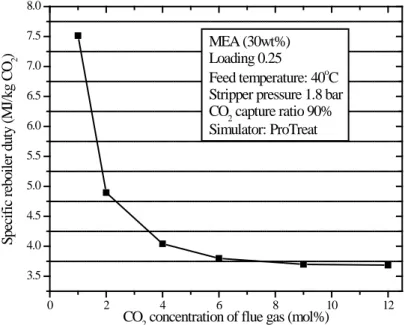
solvent degradation. It has been verified that the reboiler duty of the stripping column is sensitive to the CO2 concentration of exhaust gas [5, 6]. As shown in Figure 1, for a CO2
concentration increase from 1 to 6 mol %, the specific reboiler duty decreases sharply, from 7.5 to 3.76 MJ/kg CO2. Beyond this range, the specific reboiler duty continues to decrease at a
much lower rate. Continuous decrease in energy demand with increasing CO2 concentration is
mainly caused by the higher CO2 partial pressure, which increases driving forces, enables
higher effective loading, and hence favors the capture reaction.
0 2 4 6 8 10 12 3.5 4.0 4.5 5.0 5.5 6.0 6.5 7.0 7.5 8.0 S pe ci fi c r eboi le r dut y ( M J/ kg C O 2 )
CO2 concentration of flue gas (mol%) MEA (30wt%) Loading 0.25
Feed temperature: 40oC Stripper pressure 1.8 bar CO2 capture ratio 90% Simulator: ProTreat
Figure 1 Energy demand of stripper at different feed CO2 concentrations
The use of gas turbines for power generation has been increasing during the last decades and is likely to grow further in the medium term. Many advanced power generation cycles have been developed to take advantage of the thermodynamic characteristics of gas turbines. However, the maximum temperature attainable in the Brayton cycle is limited by the metallurgical constraint, resulting in large excess air in the combustion stage, hence highly diluted CO2 in the exhaust gas (about 3.3 vol% dry). This is a challenge for amine-based CO2
capture as a full-scale absorption plant will have to treat large volumes of dilute gas.
Increasing CO2 concentration in exhaust gas may provide an efficient method to reduce the
high electrical efficiency penalty caused by chemical absorption. Four methods for increasing CO2 concentration applicable to gas turbine based power plant cycles have been selected and
studied. These are: 1) exhaust gas recirculation (EGR), 2) humidification (EvGT), 3) supplementary firing (SFC), and 4) external firing (EFC). The scope of the present work is to review and evaluate their potential applications in the gas turbine cycle integrated with MEA-based chemical absorption. Features and challenges related to the integration of these technologies are addressed according to their impacts on cycle efficiency, combustion, gas turbine components, and cost.
2 Input data and assumptions of simulations
In this work, gas turbine cycles have been simulated with the commercial software PRO/II [7] developed by Simulation Science Ind. PRO/II process simulation software is a steady-state simulator enabling improved process design and operational analysis. It is designed to perform rigorous mass and energy balance calculations for a wide range of chemical processes.
The input data and assumptions of simulations were defined following our previous work [8]. The compositions and properties of main streams are summarized in Table 1. The input data and assumptions for the simulations of gas turbines, compressors and CO2 transport are given
in Table 2. The input data to simulate MEA-based chemical absorption are shown in Figure 1. Table 1 Compositions and properties of streams
Stream Unit Value
Fuel stream Natural gas [9]
LHV MJ/kg 48.252 T °C 15 P bar 1 Composition CO mol% 0.5 CH4 mol% 94.4 C2H6 mol% 3.1 C3H8 mol% 0.5 C4H10 mol% 0.2 C5H12 mol% 0.2 N2 mol% 1.1 Air stream T °C 15 P bar 1 Composition N2 vol% 78.99 O2 vol% 20.65 Ar vol% 0.921 CO2 vol% 0.04 Relative humidity % 60 CO2 stream to be transported T °C 20 P bar 150
Table 2 Input data and assumptions about the simulations of chemical absorption and combined cycle
Parameter Unit Value
Gas turbine
Pressure ratio 20
Turbine inlet temperature °C 1250
Steam power cycle
Maximum steam turbine inlet T °C 460
HP steam inlet pressure bar 111
HP turbine isentropic efficiency % 92
IP steam inlet pressure bar 27
IP turbine isentropic efficiency % 92
LP steam inlet pressure bar 4
LP turbine isentropic efficiency % 89
Compressors
Type Isentropic
Isentropic efficiency % 85
Intercooling T °C 30
Stage number of air compression 1
Stage number of CO2 compression 3
Other parameters
Pump efficiency % 75
Pressure drop in heat exchangers % 3
Combustor outlet temperature °C 1328
Pressure drop in combustor % 5
ΔTmin gas/gas °C 30
ΔTmin gas/liquid °C 20
Simulation Tools
Cycle PRO/II
By correlating the simulated results, the following equation is used to predict the specific reboiler duty at different feed CO2 concentrations [6]:
Q=3.3162+0.0154*yCO2+2.0383/yCO2+2.1432/(yCO2)2 Equ. 1
Where yCO2 is CO2 mole concentration in percentage (yCO2mol%). Considering the reboiler
temperature that is about 118°C at a stripping pressure of 1.8 bar, the thermal energy required by the reboiler is provided by the steam extracted from the IP steam turbine outlet so that the saturated-steam temperature matches that of the reboiler and the defined ΔTmin for heat
transfer.
3 Selected methods for increasing the CO2 concentration of exhaust gas
3.1 Exhaust gas recirculation (EGR)
A method for increasing CO2 concentration in the gas stream at the inlet of chemical
absorption units is EGR, which at the same time can reduce the corresponding volume flow. Peeters et al. [10] predicted the potential future performance of post-combustion CO2
absorption in combination with a natural gas combined cycle (NGCC). In [10], EGR was considered as an important technology for reducing energy penalty of CO2 capture, improving
net cycle efficiency and reducing capital cost (CAPEX), cost of electricity (COE) and CO2
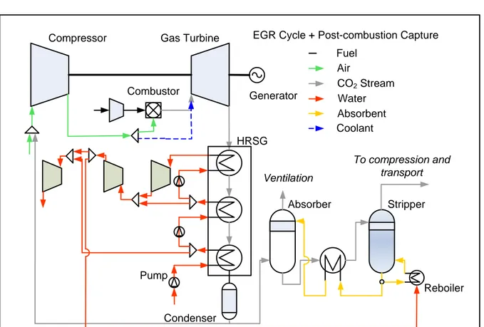
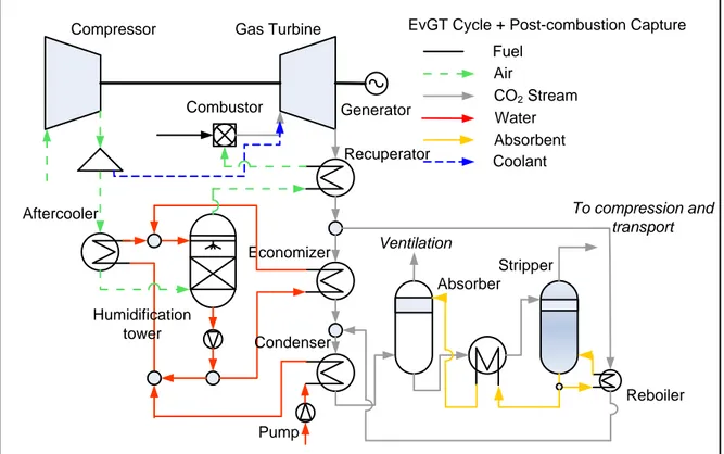
A system scheme of a combined cycle integrated with EGR and chemical absorption is shown in Figure 2. After passing through the bottoming cycle, a partial stream of the exhaust gas is extracted downstream of the exhaust gas condenser and mixed with the inlet air upstream of the compressor. Here, EGR ratio is defined as:
on condensati after gas exhaust of flow olume gas exhaust ed recirculat of flow olume EGR v v = Equ. 2 Combustor
Compressor Gas Turbine
Generator HRSG Pump To compression and transport Absorber CO2 Stream Fuel Water Air
EGR Cycle + Post-combustion Capture
Absorbent Stripper Reboiler Coolant Condenser Ventilation
Figure 2 Scheme of a combined cycle integrated with EGR and amine-based CO2 chemical
absorption
3.1.1 EGR impacts on amine-based chemical absorption
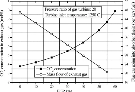
Based on simulation results, Figure 3 shows the CO2 concentration and the mass flow of the
exhaust gas entering the absorption column at different recirculation ratios. As can be observed, CO2 concentration increases and the mass flow decreases significantly as the EGR
ratio increases. Compared to a cycle without EGR, a recirculation ratio of 55% could increase CO2 concentration from 3.8 mol% to 8.7 mol% and reduce the mass flow of the absorber feed
stream by 56.2%. As a result, the total thermal energy consumption of the reboiler is reduced by 60%, and the mass flow reduction may allow for smaller sizes of absorption and stripper columns, thus contributing to a reduction in capital cost. According to Røkke [11], an EGR ratio of 50% could reduce CAPEX of an amine plant by 21.1%. Even though EGR affects the specific reboiler duty significantly, its impact on the electrical efficiency is not obvious as the recirculated exhaust gas would increase the compression work, A change of EGR ratio from 0
to 55% increases the overall efficiency from 50.1 to 50.4% of natural gas (NG) LHV according to the simulations performed in this study.
0 10 20 30 40 50 60 2 3 4 5 6 7 8 9 10 11 16 20 24 28 32 36 40 44 48 52 EGR (%) F lue ga s goi ng i nt o a bs or be r ( kg/ s) ( pe r kg/ s f ue l) CO 2 c onc ent ra ti on i n e xha us t ga s ( m ol %
) Pressure ratio of gas turbine: 20
Turbine inlet temperature: 1250oC
CO2 concentration Mass flow of exhaust gas
Figure 3 CO2 concentration and mass flow of exhaust gas at the absorber inlet as function of
EGR ratio
3.1.2 EGR impacts on combustion
Since there is less oxygen available in the exhaust gases than in ambient air, O2 concentration
before and after combustion decreases with increasing EGR ratio. As shown in Figure 4, in order to achieve complete combustion, EGR cannot theoretically exceed 60%, at which stoichiometric combustion is reached.
0 10 20 30 40 50 60 0 4 8 12 16 20 24
Pressure ratio of gas turbine: 20 Turbine inlet temperature: 1250oC
O 2 c onc ent ra ti on ( m ol % ) Excess O2
O2 concentration before combustion
EGR (%)
Figure 4 O2 concentrations in the recirculated exhaust gas at different EGR ratios
However, from the viewpoint of combustion, it is of importance to control oxygen concentration before combustion. Burners and combustors are generally designed for air
containing 21 mol% oxygen, and by recycling exhaust gas the global oxygen concentration at the combustor inlet decreases considerably, to for example 11mol% at 55% EGR ratio. With vitiated air, severe problems are prone to occur regarding combustion stability, efficiency and emission, particularly in gas turbine combustors, characterized by high velocity and low residence time. Elkady et al. [12] studied the behavior of combustion in a 10 bar Dry Low NOx (DLN) combustor with 35% EGR. This combustor was proposed for the plant design in
order to avoid potentially challenging gas turbine operating regimes with respect to combustion. The results indicated that low oxygen concentration could ‘reduce the reaction rates, allow for combustion to spread over a large region and reduce the peak flame temperature, which is not in favor of the oxidation of CO to CO2; on the contrary, reduction in
oxygen levels combined with supplementary CO2 in the oxidizer leads to changes in the heat
release process via CO2 dissociation’. Ditaranto et al. [13] experimentally studied the effect of
O2 vitiation in an atmospheric laboratory-scale setup, showing that even though the flame
could be sustained at O2 concentration as low as 14% in the oxidizer, the levels of unburned
hydrocarbons and CO were excessively high when the O2 concentration reached 16%. Taking
that limit as an indication, Figure 4 shows that EGR exceeding 40% could be difficult to obtain. This limit can, however, be pushed further by technical adaptation of the engine and combustor arrangement that would allow for additional O2 injection or different air
distribution spilt as suggested in Li et al. [6].
On the other hand, the low oxygen concentration is beneficial with respect to NOx formation,
as the latter depends on oxygen concentration as well as flame temperature, which are both reduced as EGR ratio increases. In addition, recycling minor species as NO and CO into the combustion zone tends to reduce their concentrations through, for example, the potential NO reburning mechanism [13]. In the study of Elkady et al [9] the NOx emissions decreased with
increasing EGR levels by more than 50% with 35% EGR. For the chemical absorption process, the presence of oxygen could cause degradation of amines, and the byproducts lead to corrosion problems. Hence, EGR could also minimize the need for chemical inhibitors or process modification involving deoxidation of the CO2-rich amine [14].
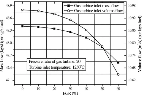
3.1.3 EGR impacts on turbomachinery
Figure 5 shows the gas turbine inlet mass/volume flow at different EGR. As can be observed, both mass and volume flows decrease with increasing EGR ratio. The decrease of gas turbine inlet mass flow can be explained by the fact that the recirculated exhaust gas has a higher temperature (40°C) than air (15°C). In order to achieve the same preset combustion temperature (1328°C), a smaller mass flow is required when some of the colder air is replaced by the hotter exhaust gas. However, the impacts of EGR on the gas turbine inlet mass flow are not obvious. An EGR of 50% varies the mass flow only by 1.04wt%, and correspondingly the volume flow by 1.61vol%. In addition, the specific heats of O2, N2 and CO2 are close. Hence,
for gas turbines and compressors, it is likely that the aerodynamic and thermodynamic changes due to the changes in composition of the working fluid may be handled without modifications.
0 10 20 30 40 50 60 47.1 47.4 47.7 48.0 48.3 48.6 48.9 10.62 10.68 10.74 10.80 10.86 10.92 10.98
Pressure ratio of gas turbine: 20 Turbine inlet temperature: 1250oC
V ol um e f low ( m 3 /s ) ( pe r kg/ s f ue l) M as s f low ( kg/ s) ( pe r kg/ s f ue l) EGR (%)
Gas turbine inlet mass flow Gas turbine inlet volume flow
Figure 5 Gas turbine inlet mass/volume flows at different EGR
3.2 Gas turbine humidification
The driving forces for gas turbine humidification have been the potential of high electrical efficiency and specific power output, reduced specific investment cost, reduced NOx
emissions, reduced power output degradation caused by high ambient temperatures or low ambient pressures (i.e. at high elevations), and improved part-load performance compared with combined cycles. Humidified gas turbines have a thermodynamic potential of electrical efficiencies similar to or higher than that of combined cycles (CC) [15] and can be divided into three categories: (I) gas turbines with injection of water that evaporates completely in or after compressors, (II) gas turbines with injection of steam (STIG), and (III) gas turbine cycles with injection of water in a humidification tower, with a recirculation water loop (EvGT).
When water or steam is introduced in the cycle, a part of air is effectively replaced by steam. Since steam could be easily separated from exhaust gas by condensation, gas turbine humidification could have a higher CO2 concentration than the conventional gas turbine cycle,
which would favor the CO2 capture process by chemical absorption.
EvGT integrated with MEA-based chemical absorption was studied by Li et al. [16] and a system scheme is shown in Figure 6. Water is heated close to the saturation point by the compressed air in the aftercooler and by exhaust gas in the feedwater heater and economizer. The heated water enters at the top of a humidification tower and is brought in contact counter-current with the compressed air that enters as the bottom of the tower. The tower is a column with a packing that is either structured or dumped. Some of the water is evaporated and the air is humidified, and the evaporation occurs at the water boiling point corresponding to the partial pressure of water in the mixture, that is, below the boiling point that corresponds to the total pressure in the tower. Hence, low temperature heat can be recovered in an EvGT cycle. Since the water vapour content in the air increases as the air passes upward through the tower,
the boiling temperature also increases. This ensures a close matching of the air and water temperature profiles, and small exergy losses compared to evaporation in a conventional steam boiler [15]. Moreover, as the heat involved in exhaust gas is recovered back to the cycle by evaporating water in the humidification tower, there is no need for a bottoming steam cycle in an EvGT system, thus lowering the investment cost.
Combustor
Compressor Gas Turbine
Generator Recuperator Economizer Aftercooler Humidification tower Pump Absorber Condenser CO2 Stream Fuel Water Air
EvGT Cycle + Post-combustion Capture
Absorbent Stripper Reboiler Coolant To compression and transport Ventilation
Figure 6 System scheme of EvGT cycle integrated with amine-based CO2 capture
With the same parameters of the gas turbine cycle, EvGT integrated with MEA-based chemical absorption were simulated at different water/air ratio (WAR) defined as:
tower tion humidifica air of flow mass water evaporated of flow mass A W = Equ. 3
WAR is of great importance for the electrical efficiency of an EvGT cycle. For every case with constant combustion air temperature, there always exists an optimum point [17].
3.2.1 Impacts of gas humidification on amine-based chemical absorption
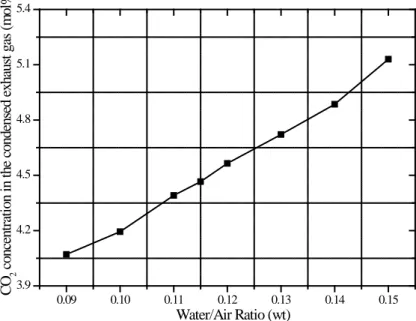
As shown in Figure 7, the CO2 concentration in exhaust gas of EvGT cycle could be raised to
above 5mol% after condensation. However, injecting water increases water concentration of the condensed exhaust gas at the same time. The molar fraction of H2O is raised from
4.3mol% in the simple cycle to 7.4mol%. The high water content of exhaust gas would bring more water into absorber and dilute the MEA solution, resulting in an increased specific reboiler duty. An optimized value of electrical efficiency regarding WAR is 41.6% of NG LHV at WAR=0.115 [16]. However, compared to a combined cycle integrated with chemical
absorption, in which electrical efficiency is calculated to 50.1% of NG LHV, EvGT does not show any promising results in the present work.
0.09 0.10 0.11 0.12 0.13 0.14 0.15 3.9 4.2 4.5 4.8 5.1 5.4 CO 2 c onc ent ra ti on i n t he c onde ns ed e xha us t ga s ( m ol % ) Water/Air Ratio (wt)
Figure 7 CO2 concentrations in the dehydrated exhaust gas at different WAR
0.09 0.10 0.11 0.12 0.13 0.14 0.15 16.4 16.6 16.8 17.0 17.2 17.4 17.6 17.8 18.0 18.2 13 14 15 16 17 18 19 20 21 22 O2 c onc ent ra ti on m ol % H 2 O c onc ent ra ti on ( m ol % ) Water/Air Ratio (wt)
O2 concentration before combustion H2O concentration before combustion
Figure 8 Oxygen concentration before combustion and water concentration in the gas turbine inlet stream
3.2.2 Impacts of gas humidification on combustion
As a part of air is replaced by water steam, EvGT cycles are characterized by lower oxygen concentration prior to combustion and higher water concentration at the gas turbine inlet, compared to conventional gas turbine cycles. The extent to which O2 and H2O vary is shown
in Figure 8 as a function of WAR. As H2O acts as a diluent, the effects are similar to those of
the optimal WAR level, the O2 concentration is likely close to the acceptable limit as far as
combustion is concerned.
3.2.3 Impacts of gas humidification on turbomachinery
Humidification of the gas turbine working fluid would cause a volumetric flow rate mismatch between the compressor and expander. This degree of mismatch depends on WAR and gas turbines that can accommodate the increased flow rate are still to be developed. As only steam-injected gas turbines are commercially available today, the high efficiencies of turbomachineries cited in many theoretical studies cannot be achieved, or are very uncertain.
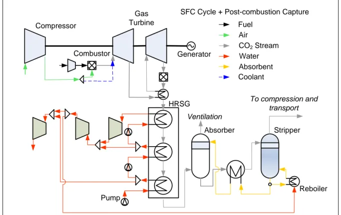
3.3 Supplementary fired gas turbine cycle (SFC)
The technology of supplementary firing is another option that could enhance the CO2
concentration of exhaust gas for post-combustion capture. A scheme of a natural gas combined cycle integrated with supplementary firing is shown in Figure 9. The major difference between SFC and the conventional combined cycle is the presence of a secondary combustion unit at the exit of gas turbine in the SFC case. By burning additional fuel, exhaust gas is re-heated and sent to a heat recovery steam generator (HRSG) to generate steam for the bottoming cycle. In order to further improve efficiency, after partial expansion in a primary gas turbine, exhaust gas is re-heated before entering the low-pressure gas turbine stage.
Combustor Compressor Gas Turbine Generator HRSG Pump To compression and transport Absorber CO2 Stream Fuel Water Air
SFC Cycle + Post-combustion Capture
Absorbent
Stripper
Reboiler Coolant
Ventilation
Figure 9 Scheme of a natural gas combined cycle integrated with supplementary firing
In general, a supplementary fired plant inherently has lower efficiency than that of a conventional plant, however the ability to produce more power output during periods of high electricity prices gives it an economic advantage depending on the demand for the electricity
and the number of hours when the high prices exist [18]. The benefits of supplementary fired combined cycle plant depend on a number of factors: plant design, cost of capital, cost of fuel, marginal cost of electricity production, and hours of operation are the most important. Since many variables are involved, most notably plant design and regional wholesale electricity prices, any particular application should be analyzed in detail to determine the full merit of adding a supplementary firing unit.
3.3.1 Impacts of supplementary firing on amine-based chemical absorption
From the viewpoint of post-combustion CO2 capture, supplementary firing shows potential
advantages. Similarly to EGR, supplementary firing could increase the CO2 concentration in
exhaust gas. Compared to a cycle without EGR, the CO2 concentration is increased from 3.8
to 6.7mol%. However, supplementary firing results in an increased mass flow of exhaust gas, which is the opposite effect from that of EGR. The increase in mass flow counteracts the benefit of high CO2 concentration and hence, SFC has a somewhat lower electrical efficiency
of 48.1% of NG LHV, according to the simulations conducted in this paper. Another factor contributing to lowered efficiency is the high temperature difference for the HRSG heat exchangers. Hence, a bottoming cycle with higher temperature, for instance a supercritical bottoming cycle, may contribute to improved efficiency.
3.3.2 Impacts of supplementary firing on combustion
A similar characteristic between EGR and SFC is low oxygen concentration in exhaust gas. However, the high temperature generally compensates for the low levels of oxygen concentration, around 12mol%, and stabilisation is often insured with simple burner ramps. In addition, high NOx reductions have also been observed in gas turbines with supplementary
firing units [13].
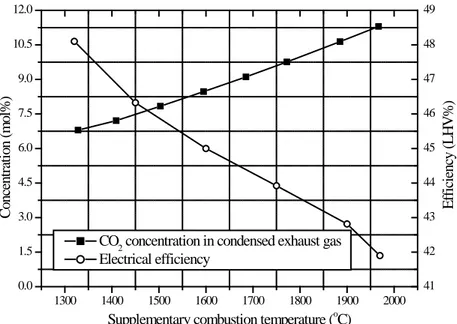
If higher combustion temperature can be applied, instead of the assumption (Tcombustion =
1328°C), CO2 concentration can be further enhanced. Figure 10 shows the CO2 concentration
in the condensed exhaust gas while Figure 11 shows the oxygen concentrations before and after combustion in the supplementary firing unit. At stoichiometric combustion, CO2
concentration approaches the theoretical maximum value, which is 11.3mol%. Furthermore, the oxygen concentration before the supplementary combustion declines with the increase of combustion temperature, but not significantly, and the increased combustion temperature could mitigate the problem of low O2 concentration.
1300 1400 1500 1600 1700 1800 1900 2000 0.0 1.5 3.0 4.5 6.0 7.5 9.0 10.5 12.0 41 42 43 44 45 46 47 48 49 E ff ici en cy ( L H V % ) C onc ent ra ti on ( m ol % )
Supplementary combustion temperature (oC) CO2 concentration in condensed exhaust gas Electrical efficiency
Figure 10 CO2 concentrations in exhaust gas and electrical efficiency of SFC at different
supplementary combustion temperatures
1300 1400 1500 1600 1700 1800 1900 2000 0 2 4 6 8 12.04 12.18 12.32 12.46 12.60 O 2 c onc ent ra ti on i n s uppl em ent ar y c om bus tor ( m ol % ) E xc es s oxyge n ( m ol % )
Supplementary combustion temperature (oC) Excess oxygen after supplementary firing
Oxygen concentration in supplementary combustor
Figure 11 Oxygen concentrations before and after combustion in the supplementary combustor at different combustion temperatures
3.3.3 Impacts of supplementary firing on cycle efficiency and gas turbine
As mentioned above, the increase in mass flow counteracts the benefit of high CO2
concentration. Consequently, along with the increase of supplementary combustion temperature, the cycle efficiency drops and approaches the lowest level at stoichiometric combustion, which is only 41.9% of NG LHV, as shown in Figure 10.
As the exhaust gas discharged from the high-pressure gas turbine stage can be re-heated indirectly in the supplementary combustor to improve the gas turbine cycle efficiency, the
material of gas turbine does not represent a problem as long as turbine inlet cooling and a high temperature-tolerant heat exchanger are applied. More details about high-temperature heat exchangers are given in section 3.4, but a new design of gas turbine to satisfy the recuperation of exhaust gas is required. In addition, if the system is simplified by skipping exhaust gas recuperation, turbine machinery would be kept unmodified and the cycle efficiency reduced by only 0.3% of NG LHV at a supplementary combustion temperature of 1320°C.
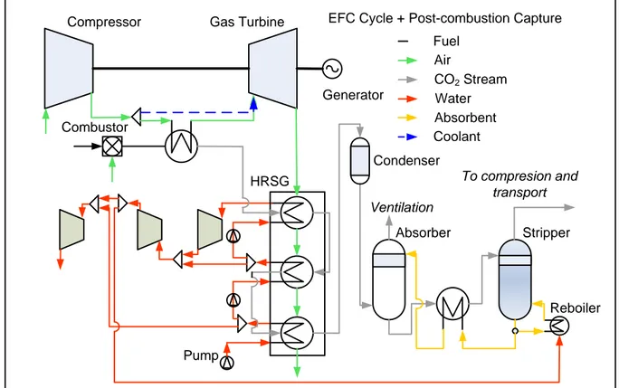
3.4 Externally Fired gas turbine Cycle (EFC)
As analyzed in the previous sections, there are potential problems associated with integration of conventional gas turbine cycles with EGR or air humidification, such as unstable combustion caused by low oxygen concentration, new design requirements of gas turbines to handle altered exhaust gas composition, and mass mismatch. These problems may be avoided with the application of external firing technology.
The EFC has been studied for coal since the 1930s, as summarized by Keller [19]. In the 1950s and 1960s, several works were conducted regarding the externally fired combined cycle concept [20,21]. Six coal and peat-fired air heaters built between 1956 and 1961 were used to understand the features of EFC. [22].. From 1990, research interest was directed towards the application in the combined heat and power plants utilizing biomass [17,23,24].
Whereas in conventional gas turbines the compressed air-fuel mixture is burnt in the combustor and subsequently expanded in the turbine, the combustion gases do not pass through the turbine in an externally fired gas turbine cycle. As shown in Figure 12, heat from the hot exhaust gas is transferred to the compressed air in an indirect contact heat exchanger. The externally fired gas turbine unites several advantages, such as the possibility of burning so-called ‘dirty’ fuel and employing a low-temperature cleanup system. It also avoids problems related to changes in gas characteristics through the compressor and turbine. Furthermore, the combustion unit does not need to be under the high-pressure environment as is the case for a conventional gas turbine.
Compressor Gas Turbine Generator HRSG Pump To compresion and transport Absorber CO2 Stream Fuel Water Air
EFC Cycle + Post-combustion Capture
Absorbent Stripper Reboiler Combustor Condenser Coolant Ventilation
Figure 12 Scheme of externally fired gas turbine cycle
The main technical impediment of EFC is the high-temperature heat exchanger, which requires robust materials in order to operate at required temperature levels for a high-efficiency cycle. Because metallic heat exchangers used in the earlier versions of the cycle did not allow sufficiently high turbine inlet temperatures for profitable power production, ceramics that can stand temperatures above 1400°C in corrosive coal combustion gas environment was used instead. Hague International conducted a series of experiments with ceramic materials in the 1970s [25]. Most of the work during this period was focused on heat recovery equipment for the secondary metals industry. To date, their low-pressure ceramic air heaters have accumulated over two million hours of successful operation in corrosive, high-temperature industrial environments. Also in the early 1980s, Hague International initiated work to increase the pressure capability (up to 100bar) of the ceramic heat exchangers [22].
3.4.1 Impacts of externally firing on amine-based chemical absorption and cycle efficiency If CO2 is to be captured by amine-based chemical absorption, EFC provides potential
advantages. For an externally fired gas turbine cycle, since the power generation and combustion units are separated, it is may not be necessary to keep the combustion at as high excess air levels as for conventional gas turbines. Hence, the flue gases can be less diluted, resulting in lower volumes to treat in an amine scrubber. In this study an EFC was simulated under the conditions listed in Table 1 and 2, except for the combustion temperature. The resulting variation in CO2 concentration and mass flowrate of the condensed exhaust gas at
different levels of excess oxygen are shown in Figure 13. As a result, the net electrical efficiency increases as the excess air ratio approaches stoichiometric condition, as shown in
Figure 14. In the theoretical case of stoichiometric combustion, CO2 concentration would be
increased to 11.8mol% and the mass flow reduced to 17.1kg/s, leading to an electrical efficiency of 44.3% of NG LHV.
3.4.2 Impacts of external firing on combustion
Figure 14 shows the adiabatic combustion temperatures of EFC at different excess oxygen, and equals 2031°C at stoichiometric combustion conditions. Conventional furnace could be used in externally firing cycle which generally operates at 3% excess O2. The major impact
would be at the gas/air heat exchanger and the selected materials.
0 1 2 3 4 5 8 9 10 11 12 16 18 20 22 24 M as s f low of c onde ns ed e xha us t ga s ( kg/ s pe r kg F ue l) CO 2 i n c onde ns ed e xha us t ga s ( m ol % ) Excess O2 mol%
CO2 concentrationin in the condensed exhaust gas
Mass flow of the condensed exhaust gas
Figure 13 CO2 concentrations and mass flow of the condensed exhaust gas at different levels
of excess oxygen 0 1 2 3 4 5 42.5 43.0 43.5 44.0 44.5 45.0 1600 1700 1800 1900 2000 2100 A di aba ti c C om bus ti on T em pe ra tur e ( o C) E le ctr ic al E ff ic ie nty ( L H V % ) Excess O2 (mol%) Electrical Efficiency Combustion Temperature
Figure 14 Electrical efficiency and combustion temperatures of EFC at different levels of excess oxygen
4 Discussion
Based on the above analysis, Table 3 summarizes the characteristics of different technologies considered in this work, including advantages, challenges and key parameters. Furthermore, the calculated electrical efficiencies of the different cycles are displayed in Figure 15.
0 10 20 30 40
50 Potential improvement by varying key parameters
EFC SFC EvGT EGR E lect ri cal ef fi ci en cy ( L H V % )
Figure 15 Calculated electrical efficiencies of the different cycles in consideration
according to the simulation results of this study, EvGT has the lowest electrical efficiency, while EGR has the highest. One of the important advantages of EvGT lies in the augmentation of the gas turbine flowrate obtained through water evaporation. However, when integrated with amine-based chemical absorption, this technology becomes less advantageous due to several reasons. As amine regeneration inherently consumes large amounts of heat, less heat is available to humidify air. Thus, the amount of water evaporated in the humidification tower is reduced sharply. Furthermore, as EvGT requires high-temperature exhaust gas for the supply of thermal energy to the reboiler, the large temperature difference at the heat transfer sections will further contribute to efficiency losses. In addition, as the exhaust gas pressure is close to atmospheric, a large amount of latent heat of water condensation cannot be utilised in the stripper reboiler as normally done in combined cycles due to the low condensing temperature. This further reduces the cycle efficiency. EGR shows higher efficiency than SFC and EFC due to more energy-efficient thermal integrations between the involved sub-processes. Compared to SFC, EGR is characterized by smaller temperature differences between the exhaust gas and the maximum steam turbine inlet temperature in the HRSG, for the EGR case around 40°C while 480°C for SFC. Finally, compared to EFC, internal combustion with compressed air has a higher thermal efficiency than external combustion with indirect heat transfer from the combustion products to the internal gas turbine cycle.
For the power cycles considered in the present work, further modifications can potentially improve the overall efficiencies. In the case of EvGT, efficiency may be improved by integrating a bottoming cycle running at low temperature, such as organic Rankine cycles working with R113 and R245 whose maximum working temperatures are in the range of 200–
320°C [26,27]. For SFC, a supercritical bottoming cycle may utilise thermal energy more efficiently than a subcritical cycle due to the high exhaust gas temperature. In the case of EGR, higher EGR ratios can further increase CO2 concentration and reduce the mass flowrate
of exhaust gas to be treated in a chemical absorption plant. However, in order to reduce EGR impacts on combustion, local oxygen enrichment may be required. Hence, integrating a low-purity oxygen air separation unit (ASU), cryogenic or possibly utilising oxygen membrane technology, could be a potential way to improve the overall efficiency of EGR with CO2
capture.
5 Conclusions
As enhanced CO2 concentration in exhaust gas being a potentially effective method to reduce
the high electrical efficiency penalty caused by chemical absorption, four technologies enabling increased CO2 concentration have been reviewed and evaluated: exhaust gas
recirculation, gas turbine humidification, supplementary firing and external firing.
From the viewpoint of improving capture conditions, exhaust gas recirculation can potentially increase the molar fraction of CO2 from 3.8 mol% to 10 mol% or possibly higher, while air
humidification may increase the CO2 fraction to around 5 mol%. For supplementary firing
and externally fired cycles, the theoretical maximum CO2 concentrations are 11.3 mol% and
11.5 mol%, respectively, in the case of stoichiometric combustion.
As far as electrical efficiency is concerned, the simulation results presented in this paper show that the system integrated with EGR shows the best performance while the system integrated with air humidification shows the lowest efficiency.
Regarding investment cost, EvGT cycle has a relatively low cost due to the absence of bottoming cycle, while supplementary firing has a relatively high cost due to its additional burner. And comparatively, externally fired technology has the minimum impacts on both combustion and turbomachinery.
Acknowledgements
This publication has been produced with support from the BIGCCS Centre, performed under the Norwegian research program Centres for Environment-friendly Energy Research (FME). The authors acknowledge the following partners for their contributions: Aker Solutions, ConocoPhilips, Det Norske Veritas AS, Gassco AS, Hydro Aluminium AS, Shell Technology Norway AS, Statkraft Development AS, Statoil Petroleum AS, TOTAL E&P Norge AS, GDF SUEZ E&P Norge AS and the Research Council of Norway (193816/S60).
Table 3 Summary of the characters of different technologies
Character Technology
EGR EvGT SFC EFC
Impact on amine-based chemical absorption
CO2-enriched exhaust gas +++ + ++ ++
Exhaust gas mass flow reduction ++ + - + Low O2% ++ + ++ ++ Impact on combustion Reduction of NOx + + + -
Demand of extra oxygen + - - None
Potential problems Stability, CO/UHC Stability, CO/UHC Unstable combustion None
Impact on turbine Potential problems High CO2
concentration High H2O concentration, mass mismatch None None Impact on efficiency Thermal integration + - - - Possible electrical efficiency (% NG LHV) 50.1-50.5 39.7-41.6 41.9-48.9 42.8-44.3
Impact on cost reduction + ++ - +
Key parameter Recirculated mass
flow
WAR Supplementary
combustion temperature
Excess O2
Additional requirements/problems New design of
combustion chamber Humidification tower, make-up water system Supplementary duct burners, high temperature heat exchanger
High temperature heat exchanger, material selection
NOMENCLATURE
P Pressure
Q Specific reboiler duty (MJ/kg CO2)
T Temperature
yCO2 CO2 mole concentration in percentage
λ Excess air ratio
Abbreviations:
CC Combined cycle
CCS CO2 capture and storage
COA COE
CO2 avoidance cost
Cost of electricity
DLN Dry low NOx
EFC Externally Fired cycle
EGR Exhaust gas recirculation
Equ Equation
EvGT Evaporative gas turbine
HP High pressure
HRSG Heat recovery steam generator
IP Intermediate pressure
LHV Lower heating value
LP Low pressure
MDEA Methyldiethanolamine
MEA Monoethanolamine
NG Natural gas
NGCC Natural gas combined cycle
ORC Organic Rankine Cycles
SFC Supplementary Firing Cycle
SRK Soave-Redlich-Kwong
STIG Gas turbines with injection of steam
TET Turbine exit temperature
TIT Turbine inlet temperature
UHC Unburned hydrocarbon
vol Volume
WAR Water air ratio
wt Weight
References
[1] Barchas R., Davis R., The Kerr-McGee/ABB Lummus Crest Technology for the Recovery of CO2 from Stack Gases. Energy Convers. Mgmt, 33(5-8):333-340, 1992.
[2] Sander M.T., Mariz C.L., The Fluor Daniel ® EconamineTM FG Process: Past Experience and Present Day Focus. Energy Convers. Mgmt, 33(5-8):341-348, 1992.
[3] Chapel D.G., Mariz C.L., Ernest J., Recovery of CO2 from flues gases: commercial trends.
In: Proceedings of annual meeting of the Canadian Society of Chemical Engineering, Saskatoon, Canada, 1999.
[4] Mimura T., Nojo T., Ijima M., Yoshiyama T., Tanaka H., Recent developments in flue gas CO2 recovery technology, In: Proceedings of 6th International Conference on Greenhouse Gas
Control Technologies (GHGT-6), Kyoto, Japan, 2002.
[5] Aboudheir A., ElMoudir W., Performance of formulated solvent in Handling of enriched CO2 flue gas stream, Energy Procedia 1:195-204, 2009
[6] Li H., Haugen G., Ditaranto M., Berstad D., Jordal K., Impacts of exhaust gas recirculation (EGR) on the natural gas combined cycle integrated with chemical absorption CO2 capture technology, In: Proceedings of the 10th International Conference on Greenhouse
Gas Control Technologies (GHGT-10), Amsterdam, Netherlands, 2010.
[7] SimSci-Esscor. http://iom.invensys.com/EN/Pages/SimSci-Esscor_ProcessEngSuite_PROII.aspx.
[8] Kvamsda HM, Jordal K, Bolland O. A quantitative comparison of gas turbine cycles with CO2 capture. Energy 2007; 32:10-24.
[9] Intergovernmental Panel on Climate Change (IPCC), IPCC special Report on Carbon Dioxide Capture and Storage, Cambridge University Press, 2005.
[10] Peeters A.N.M., Faaij A.P.C., Turkenburg W.C., Techno-economic analysis of natural gas combined cycles with post-combustion CO2 absorption, including a detailed evaluation of
the development potential, Int. J. Greenhouse Gas Control, 1:396-417, 2007.
[11] Røkke P.E., Environmental use of natural gas in a gas turbine, Doctoral thesis of Norwegian University of Science and Technology, 2006.
[12] Elkady A., Evulet A., Brand A., Ursin T.P., Lynghjem A., Application of Exhaust Gas Recirculation in a DLN F-Class Combustion System for Post combustion Carbon Capture, Journal of Engineering for Gas Turbines and Power, 131(3), 034505, 2009.
[13] Ditaranto M., Hals J., Bjørge T., Investigation on the in-flame NO reburning in turbine exhaust gas, Proc. Combustion Institute, 32:2659-2666, 2009.
[14] Chakravarti S., Gupta A., Hunek B., Advanced technology for the capture of carbon dioxide from flue gases, In: Proceedings of 1st National Conference on Carbon Sequestration, 2001.
[15] Jonsson M., Yan J., Humidified gas turbines—a review of proposed and implemented cycles. Energy 30(7):1013-1078, 2005.
[16] Li H., Flores, S., Hu, Y., Yan, J., Simulation and Optimization of Evaporative Gas Turbine with Chemical Absorption for Carbon Dioxide Capture, Int. J. Green Energy, 6:(5), 527-539, 2009.
[17] Yan J., Eidensten L., Svedberg G., An investigation of the heat recovery system in externally fired evaporative gas turbines, In: Proceedings of ASME International Gas Turbine and Aeroengine Congress and Exposition, Houston, Texas, USA, 1995.
[18] Backlund J., Froemming J., Thermal & Economic Analysis of Supplementary Firing
Large Combined Cycle Plants, Coen Company,
Inc. http://www.coen.com/i_html/white_ductecon902.html
[19] Keller C., The Escher Wyss-AK closed cycle turbine, its actual development and future prospects, Trans. ASME, 68:791-882, 1946.
[20] Keller C., Gaehler W., Coal-burning gas turbine, In: Proceedings of the Gas Turbine Power Conference, ASME, Washington D.C., USA, 1961.
[21] LaHaye P.G., High temperature heat exchanger for closed-cycle, coal-fired gas turbines, In: Proceedings of National Coal Conference and Association Sales Conference and Bituminous Coal Research Annual Meeting, Pittsburgh, USA, 1966.
[22] LaHaye P.G., Zabolotny E., Externally-fired combined cycle (EFCC), In: Proceedings of ASME Cogen-Turbo Meeting, Nice, France, 1989.
[23] Eidensten L., Yan J., Svedberg G., Biomass externally fired gas turbine cogeneration, In: Proceedings of International Gas Turbine and Aeroengine Congress and Exposition, Hague, Netherlands, 1994.
[24] Kautz M., Hansen U., The externally-fired gas-turbine (EFGT-Cycle) for decentralized use of biomass, Applied Energy 84:795-805, 2007.
[25] Most I.G., Hagen K.G., A ceramic heat exchanger for exhaust-fired gas turbine power cycle, In: Proceedings of the 12th Intersociety Energy Conversion Engineering Conference, 1977.
[26] Najjar Y.S.H., Efficient use of energy by utilizing gas turbine combined systems, Applied Thermal Engineering 21:407-438, 2001.
[27] Chacartegui R., Sánchez D., Muñoz J.M., Sánchez T., Alternative ORC bottoming cycles for combined cycle power plants, Applied Energy, 86:2162-2170, 2009.