1
A Mutation Analysis Framework for
Simulink Models
Mälardalens Högskola
Akademin för Innovation, Design och Teknik
Henrik Runge
hre13001@student.mdh.se
Bachelor of Computer Science
2018-01-10
Examiner: Professor Daniel Sundmark
2
Contents
1. Introduction ... 4 2. Background ... 5 2.1 Mutation testing ... 5 2.2 Simulink ... 5 2.3 SIMPPAAL ... 6 2.4 MATS ... 6 3. Related Work ... 6 4. Problem Formulation ... 8 5. Method ... 86. A Framework Tailored for Mutation Analysis of Simulink Models ... 10
6.1 Framework Overview ... 10
6.2 Mutation classification ... 11
6.3 Mutation of the Simulink Models ... 12
6.4 Mutator.exe ... 13
7. Validation ... 16
7.1 Volvo Brake-by-Wire ... 16
7.2 Mutator.exe application on BBW-system ... 16
7.3 SIMPPAAL-integration ... 18
7.4 MATS-integration ... 18
7.5 Discussion ... 18
8. Threats to validity ... 19
9. Conclusion and Future Work ... 19
3
Abstract
Mutation analysis is a fault-based method used for introducing small changes into a program, producing mutants based on mutation operators, classes of commonly occurring faults. Mutation analysis has been used in the last couple of decades for evaluating how good test cases produced by software testing are at detecting faults. Software testing is the process of executing software based on certain input parameters and evaluating its behavior with the purpose of finding faults and making sure that the software works as expected.
In automotive systems, MATLAB Simulink is the facto standard for implementing the electronic control software of vehicle functions. As such, the application of software testing and mutation analysis to Simulink models becomes a crucial aspect for providing a framework to evaluate existing test cases by introducing mutations into these models.
In this thesis, we propose a mutation generation framework for Simulink by using a set of mutation operators defined based on our own classification based on the Simulink project structure and previously defined operators. Our method is supported by the tool SIMUTATOR, which we also introduce and apply on an industrial prototype called the Brake-By-Wire system. This work enables the mutation analysis of industrial Simulink models. In addition, we show how SIMUTATOR can be used together with SIMPAAL (a tool for transforming Simulink models to timed automata) and MATS (a tool for test generation) for mutation testing. The results show that SIMUTATOR is efficient and can be used successfully on industrial-sized Simulink software.
4
1.
Introduction
Testing modern automotive systems is a challenging part of software development and is an important process for ensuring the system quality. Mutation testing [1] has been widely used to assess the fault-detection effectiveness of tests, as well as to guide test case generation. Mutation testing is a technique used to perform white-box testing that can be used to create “good” tests at detecting mutants. Alternatively, mutation analysis can be used to assess test effectiveness (in terms of mutation detection) of already created tests. A mutant is a new version of the software created by making a small change to the original software – this may be something as simple as changing an add (+) operator to a subtraction (-); the execution of a test on the resulting mutant may produce different behavior than the original program, in which case we say that the test case kills that mutant; the test case is good at detecting that mutant. In practice, the source code is itself modified (e.g., mutated) in order to observe how the behavior changes.
While mutants have been shown experimentally to be representative of real faults [2] when applied on “traditional” software, mutation testing requires mutation operators specific to each application domain and programming language. For example, in the automotive domain, Simulink is used for developing safety critical control software. Even if there is a large body of knowledge on mutation testing [1], few approaches have applied mutation testing to Simulink models and evaluated it using industrial software. [3]
An example of an existing taxonomy (classification) of mutations are given in a taxonomy for Simulink models [4][5] in which mutants are divided into classes based on what changes they bring to the behavior. One such class is the “Add or Delete Block as Destination (mADBD)” which is part of the “Change Subsystems Structure”-category.
In this thesis, we propose and develop a framework for automatic mutant generation which can be used together with test generation
[6]
for testing Simulink models. We develop mutation operators based on our own classification and we apply these operators to an industrial prototype for evaluation. The thesis includes the following contributions:• A review on research papers on mutations and mutation testing applied to Simulink;
• The proposal of a classification of mutants in Simulink;
• The creation of an automatic mutant generation framework and tool for mutation testing using SIMUTATOR.
• Application of SIMUTATOR on an industrial prototype (Volvo’s Brake-by-Wire) in order to evaluate the feasibility of such an approach.
• Integration of SIMUATOR into an existing mutation testing tool suite together with the SIMPPAAL and MATS [6], [7] tools.
In Section 2 we introduce the reader to some need-to-know concepts regarding tools/technologies used. We present related work upon much of the work in this thesis is built in Section 3. Section 4 contains a presentation of the identified problems we address in this thesis and Section 5 (Method) we discuss how these problems are tackled. Section 6 and 7 contain information about possible ethical considerations and threats to validity, while in Section 8 we detail the framework developed during this thesis. In Section 9 the application of the tool on the Brake-by-Wire-system is shown and its integration with the MATS and SIMPPAAL tools, as well as a discussion part which covers the different challenges faced during the development of this framework. Finally, in Section 10 the future work is discussed, along with a conclusion.
5
2. Background
In this section, a few key concepts and tools used in this thesis will be introduced to the reader. These include mutation testing, Simulink language, SIMPPAAL approach for transforming Simulink into timed automata and MATS tool used for creating and evaluating tests based on the transformed timed automata tool.
2.1
Mutation testing
Model-based testing [1] is the technique of automatically generating faulty implementations of the software for assessing the fault detection ability of a test suite or for creating test cases that are maximizing the fault detection score. A mutant [8] is a changed version of the software created by making a small change to the original software. The execution of a test on the mutant could produce a different behavior than the original non-mutated software, in which case the test kills that mutant.
For example, a tester wants to apply mutation testing to a very basic calculator application which supports the four basic arithmetic operations: addition, subtraction, division and multiplication. Applying mutation testing on this application might yield that addition is treated like subtraction and vice versa, with the same being true for division and multiplication. We should mention here that operators like division and addition cannot not be swapped in this application. Each of these alterations would result in a different mutant. For the base calculator application, we would generate four mutants for each swapped functionality (e.g., addition to subtraction, subtraction to addition). In such a simple system, the mutants are very simplistic but are representing realistic faults a user would do when programming such an application. On the other hand, when applying the same basic principle to large systems which consists of countless smaller components used for computing basic arithmetic, compare input signals using relational operators, mutation testing can be a good way of examining its resilience to small faults or how prone the system might be too small errors in the code.
2.2
Simulink
MathWorks Simulink[9] is a graphical development tool used for model based development in a graphical diagram in which users can insert and connect different blocks in various configurations to achieve their implementation or create simulation models.
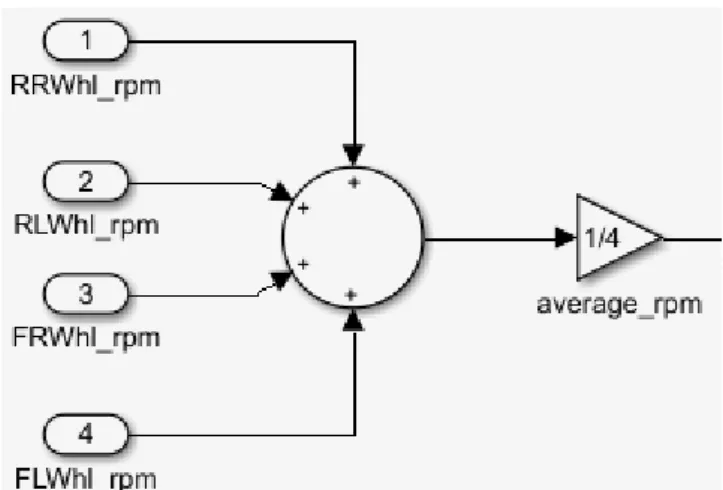
As shown in Figure 1, different predefined blocks and signals between these blocks represent a Simulink model. For example, an Add-block can take four input signals (i.e., inputs of type integer) and performs addition on these signals and then outputs that computed value via its output port. As an analogy, blocks in Simulink work similarly to functions in a C/C++ program. Blocks are divided into already defined libraries [10] based on their respective functionality; these libraries include Logic and Bit Operations (e.g., blocks like Relational Operator and Logical Operator are included) and Math Operations (e.g., blocks like Gain, Sum, Product, Divide, Add, Subtract are included).
6
Figure 1: Example of a Simulink program containing 4 input ports, an Add-block that performs addition and a Gain block calculating an average value.
2.3
SIMPPAAL
SIMPPAAL [7] is a tool used to generate a network of timed automata from the Simulink model files (.mdl) with the goal of performing formal verification and test generation based on the resulting timed automata model.
SIMPPAL proposes a pattern-based, execution-order preserving transformation using Simulink blocks into stochastic timed automata that can then be formally model checked with UPPAAL Statistical Model Checker (SMC). The user manually selects an .mdl-file, a .txt-file which specifies the execution order within it and selects the output .xml-file. When running SIMPPAAL, the tool generates a statistical model which can be opened and examined in UPPAAL SMC. The same generated model can be used using MATS for test generation.
2.4
MATS
MATS is a tool used to employ model based test generation and evaluation using manually created faulty timed automata models. The tool works using a reference and a faulty model. The reference model is used for generating tests. These tests are then executed on the faulty model to evaluate if the tests are detecting the created faults. [6] MATS is used for Model-based testing [11], [12], a technique that uses abstract models for testing the software. These models are used to describe the desired functionality from the requirements point of view. Based on these models, test cases are generated using specific test selection criteria in order to make sure that the system will be working according to its specification model. MATS is not a mutation testing tool, as the faulty models are created manually. This thesis builds upon this approach and complements this tool with a mutant creation process.
3. Related Work
Researchers have studied mutation operators for several programming languages[1]. Jia et al.[8] are outlining the history and development of mutation testing and provide an in-depth analysis and insights into mutation generation, the work done in the past on what type of mutations are most commonly used in practice for different languages, trends and statistics, as well as providing good examples of mutations (i.e., actual operators). For example, a taxonomy for Simulink model mutations [4] was defined to describe a way to categorize Simulink block mutations based on what modifications to the Simulink language these changes introduce. These categories are then also divided into sub-categories/classes in order to be separated on the basis of what types of elements these classes have. An example of a class is the renaming of a block or a line (abbreviated mRBL) which is categorized into the “Renaming and Value Modification of Elements” category.
7
Zhan et al. [13] proposed the use of search-based automatic test-data generation methods to find mutation adequate test-sets. This work shows how to create relevant test cases and evaluates the adequacy of the tests to detect the created mutants. The adequacy is defined in terms of a mutation score. The more possible faults and/or errors a test can discover using a specified test-set (based on a set of mutations), the better the test inputs are; this so-called adequacy of a test set can be determined using the following formula:
A=D/(M-E),
where A is the adequacy score, D is the number of killed mutants, M represents all mutations and E is defined as the number of semantically equivalent mutants.
Others have proposed the use of the HAZOP (Hazard and Operability) for finding suitable mutant operators [3] that could influence the typical faults one can create in Simulink. In addition, Thi My Hanh et al. [14] showed how automated test data generation based on mutation testing for Simulink models can be used for generating useful test cases. This paper provides a good overview on mutating Simulink models and describes several statistics comparing execution time, number of killed of mutants for different data sets, and a comparison of different search algorithms;
Nannan He et. al [15] propose an algorithm to generate mutation-based test cases that combines both a formal concept analysis and white-box testing and show different challenges one can encounter in the process. Several mutation operators are presented, including the constant replacement and inserting absolute value operators; mutant operators presented in this paper have been useful when developing our mutation framework.
Lionel Briand et. al [16]–[18] proposed several contributions in mutation testing of Simulink models, including fault assertion, test suite generation, and the development of a testing suite generation tool.
Recently, Larsson [6] proposed the use of automated test generation and mutation analysis using the UPPAAL SMC tool for timed automata models. This approach can be extended for Simulink models through the use of the SIMPAAL tool [19] , that provides an automatic transformation from Simulink to a network of stochastic timed automata. However, SIMPAAL lacks the capability to automatically generate mutated Simulink models based on certain mutation operators, which is the focus of this thesis.
Even if other researchers [5], [20]–[25] have extensively studied and proposed their mutation operators, there is a lack of evidence that these mutation operators are implemented in a framework and tool for mutation of Simulink models.
8
4. Problem Formulation
There is a need to investigate the use of mutation testing for Simulink models. Recently, a method has been proposed [19] to automatically create tests based on fault detection using UPPAAL SMC. To the best of our knowledge, the scientific literature lacks the tool support of automatically creating mutants that can be used for mutation analysis. The research goal of this thesis is to investigate how to automatically generate mutants for Simulink models in practice and evaluate the applicability of this proposed solution in an industrial case study.
Research goals:
• RG1: Identify a suitable set of operators for mutation analysis;
• RG2: Automatically generate Simulink mutants based on the identified sets of mutation operators;
• RG3: Apply the proposed solution on an industrial system.
5. Method
A research method is a structured and systematic process that is used to answer specific research questions or confirm a research hypothesis [26]. To achieve our research goals (RG1-RG3), we apply the following steps:
• Review the scientific literature to uncover related works and propose a set of mutation operators suitable for Simulink models.
• Refine the research goals based on the previous step.
• Propose a solution by determining the appropriate technique to automatically generate mutants for Simulink models.
• Implement the solution in a software tool.
• Validate the solution on a relevant industrial system. The results will be analyzed and discussed in terms of method applicability and efficiency.
First and foremost, a literature review was performed by surveying the related work. Earlier work on mutation analysis and testing for Simulink has been collected, examined and used to provide a basis for this thesis work. We gathered information from each of these papers including the used mutation operators and mutation taxonomies/classifications proposed.
The next step of this thesis started with an investigation of the basic structure of both a Simulink visual diagram and language using MATLAB (i.e., in terms of blocks, connections between blocks, blocks within blocks) as well as how these structures are represented within the textual model (i.e., mdl files) in terms of paths, branches and general blocks.
Once this part was finished different approaches have been evaluated. First, a basic approach was created, which created one mutation model based on one input model. After analyzing the feasibility of such an approach, other versions of the approach have been developed based on different mutation operators defined. Multiple versions of the approach were evaluated with a comprehensive set of mutants. Each iteration of the approach was validated against the Brake-by-Wire system prototype.
The mutations used in the developed framework are created by modifying the properties of specified blocks on the model. For example, a Subtract-block can be altered as an Add-block by changing the Inputs-property operator(s) of the block from “++” to “+-”. We should mention here that this is not changed to “--” since the “formula” of the block is (input1)(value1)(input2)(value2), so this “--” would become -a-b instead of (+)a-b for “+-” which would result in a higher order mutation.
9
In addition, the framework takes into account the hierarchical aspect of working in industry with layers of nested Simulink systems/models that contain components which are not basic blocks but subsystems with their own components or set of blocks. This nesting aspect adds an extra level of complexity and functionality that our framework must take into account.
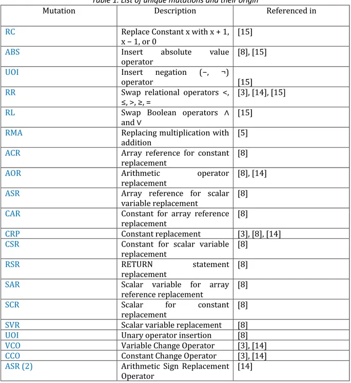
By observing the nature of the Simulink model, we wanted to consider both the complexity of nesting Simulink diagrams and the previously defined mutation operators in the literature. We performed several search queries using Google Scholar and snowballing from the papers found several more papers relevant to our framework. This information is collected in Table 1 as a list of (unique) mutation operators found and the papers describing it and has been used to identify missing mutation operators in our classification. These mutations are color coded based on the classification presented later in Section 8.1: red stands for Block/Component level (BCL), green
means Control flow (CF) within System level and blue is Data flow (DF) within System level. We note here that some of the operators can have overlapping descriptions.
Table 1. List of unique mutations and their origin
Mutation Description Referenced in
RC Replace Constant x with x + 1,
x − 1, or 0
[15]
ABS Insert absolute value
operator [8], [15]
UOI Insert negation (−, ¬)
operator [15]
RR Swap relational operators <,
≤, >, ≥, = [3], [14], [15]
RL Swap Boolean operators ∧
and ∨ [15]
RMA Replacing multiplication with
addition [5]
ACR Array reference for constant
replacement [8]
AOR Arithmetic operator
replacement
[8], [14]
ASR Array reference for scalar
variable replacement [8]
CAR Constant for array reference
replacement
[8]
CRP Constant replacement [3], [8], [14]
CSR Constant for scalar variable
replacement [8]
RSR RETURN statement
replacement
[8]
SAR Scalar variable for array
reference replacement [8]
SCR Scalar for constant
replacement
[8]
SVR Scalar variable replacement [8]
UOI Unary operator insertion [8]
VCO Variable Change Operator [3], [14]
CCO Constant Change Operator [3], [14]
ASR (2) Arithmetic Sign Replacement
10
VRO Variable replacement
operator [3]
AAR Array reference for array
reference replacement
[8]
DER DO statement alterations [8]
DSA DATA statement alterations [8]
LCR Logical connector
replacement [8]
SDL Statement deletion [8]
SCO Statement Change Operator [14]
SSO Statement Swap Operator [3], [14]
LOR Logical Operator
Replacement Operator [14]
BRO Block Removal Operator [3], [14]
INC Add constant value to a signal [8]
6. A Framework Tailored for Mutation Analysis of Simulink Models
In this section, we describe the framework for mutation analysis for Simulink models and how it was developed in terms of a tool named SIMUTATOR.6.1 Framework Overview
To fulfill RG1-3 we propose a framework based on a mutation operator classification and a mutation generation process that takes into account the nesting of Simulink models. This framework is part of a larger testing approach using SIMPPAAL and MATS. This framework coupled with the MATS-tool developed by Larsson et al. [6] and the SIMPPAAL-tool can be used for mutation testing of Simulink models using UPPAAL SMC. The framework contains the following steps (mirrored in Figure 2):
1. Mutation Operator Definition. Define a set of mutation operators using a classification. 2. Mutation Opportunity Identification. Identification of opportunities to apply the given
mutation operator. This depends on what kind of mutation operators have been defined. 3. Mutation Generation. Once the desired block(s) are found, the default model is mutated
and a new mutated Simulink model is generated (for each desired block).
After this mutation framework performs these steps, the mutated model can be passed to other tools (e.g., SIMPPAAL) to generate an executable model/network of timed automata. This model can be passed on into test generation and execution tools (e.g., MATS) in which randomly generated tests are executed on both the reference/default model and the mutated model.
11
Figure 2: The proposed framework.
6.2 Mutation classification
While the papers identified in Table 1 are focusing on mutations on the block level, in this framework we propose to use mutation operators based on the structure of a realistic Simulink model. Of course, many types of faults can occur in a Simulink model. The choice of mutation operators affects the number of mutants created. We use the following information for developing a classification for formulating general mutation operators:
• Structural Simulink Information. From observing the Brake-By-Wire system, we
identified that a Simulink model contains hierarchical diagrams that are achieved through the implementation of a subsystem, a block that encapsulates a set of atomic blocks and possibly other subsystems. In addition, the Simulink models have a data flow semantics as well as a control flow semantics that can influence the mutation created. This information should model the first level of potential faults in terms of belonging to the system as a
12
whole or each block and component and the type of information flow in the Simulink model.
• Previously Defined Mutation Operators. These already defined mutation operators
were used to identify missing classifications. Based on our observations relating to the structural Simulink information, the literature seems to be missing the definition of mutation operators related to the control flow of the Simulink models.
Based on the information gathered in the previous step for formulating general mutation operators, we propose the following classification that will be used for the creation of mutations:
• System level (SYSL)
• Data flow (DF)
• Add component (ADDC)
• Remove component (REMC)
• Replace component (REPC)
• Control flow (CF)
• Add block/set of blocks (some block work in pairs, e.g., GOTO) (ADDB)
• Remove block/set of blocks (REMB)
• Edit block/set of blocks (EDIB)
• Block/Component level (BCL)
• Edit interface (EDII)
This classification is not intended to be complete in terms of potential faults, but instead is focusing on recognizing the difference between faults in the Simulink system as a whole and faults in the block and component interface. In fact, each mutation operator (i.e., ADDC, REMC, REPC, ADDB, REMB, EDIB, EDII) is designed to model faults belonging to the corresponding fault class (i.e., SYSL, BCL, DF or CF). These mutation operators have been used to create concrete mutations in Simulink. We note here that the work done by Stephan et. al [2] has been used as input to our taxonomy as it shows different fault classes as we do, but these are specific to one Simulink diagram
.
6.3
Mutation of the Simulink Models
Mutations in the framework are performed by manipulating the structure of the Simulink system. We define how steps 1 to 3 are performed (shown previously in Section 8.1) in the following manner:
• Three major lists are used in the master function mutateFiles: one containing diagram paths to read from, one containing paths to write to, and one containing the path for the current information collection.
• The total number of instances (except the “template”-instance) of the currently selected mutation is counted in each diagram in the read-list (using the topmost diagram path) to determine the number of mutations to be made (and therefore by extension, how many initial copies to create in the original diagram).
• This information from the read-diagram is used to populate the other two lists: the write to-list is populated with write to-paths – for example, finding three possible mutations in the current read-diagram tells the framework that it needs to add three write to-diagram copies of the read-diagram (mutation M1, M2, M3, used as the name for their unique diagram folders in the destination path).
Once these steps are done, each entry in the (three) lists are mutated accordingly - a counter called desired is used alongside another counter called instances to make sure that the current instance is the desired one to mutate for this diagram. When a correct instance is found, the diagram has not been mutated earlier, so a mutation is created. For something like a relational operator-mutation, the mutation is basically done by changing the current found relational operator to
13
another one from a given list (based on what relational operator(s) were found and to avoid changing the operator to something already created).
6.4 Mutator.exe
To automate the mutation framework, we developed the SIMUTATOR tool. The current implementation is developed in Microsoft Visual Studio in C++. The initial version of the tool started as a simple console application with no user interface. Later on, we added a GUI interface. Thus, we made the decision to use Windows Forms/CLI and the project was subsequently changed to include this functionality. This is a good decision for its usability because this allows a user to take advantage of modules like list boxes and folder browsing. In terms of user interface, the tool consists of a single form window where all necessary controls are gathered: source/destination folder selection, mutation selection, a “run”-button and a label displaying the time taken to do the last mutant.
Figure 3: the interface of SIMUTATOR.
In the SIMUTATOR tool the transformation works as follows: the tool counts the number of instances in each diagram of the selected/current mutant to determine how many possible mutant opportunities exist and thus determining how many copies are needed to be of the as shown in Figure 4.
14
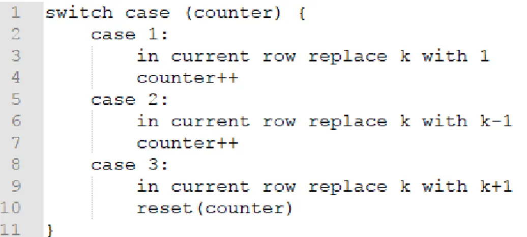
For each valid instance of Gain found, three mutations are created: the property Gain where the default value is represented with k is changed to 1, k-1 and k+1 respectively in the three corresponding mutants. If the three alternatives in the current files’ Gain property are changed by using a variable counter which is incremented for each made mutant (and then reset), as shown in Figure 5.
Figure 5: Simplified explanation on how the replacement is done for Gain; the current row is sent (which returned a match) is sent into the function to be changed for output.
We show in Figure 6 and Figure 7 the Gain-block in Simulink before and after the EDII mutation is applied. The mutation of the Gain-property happens on row 2982. The mutation applied in this case is k-1 for the value of the property.
Figure 6: The Gain-block before mutation is applied.
15
Another example of a more complex mutation is GotoFrom which switches the GotoTag between two pairs of From and Goto-blocks. GotoTag acts like the connection between two of these blocks and the transformation in SIMUTATOR works differently. The basic process is that the program finds and stores the GotoTag from the desired From-block (since they appear first in the .mdl-file), finds and stores the GotoTag from another From-block (called unique and shown in Figure 8) and then swaps these GotoTags in the pairs corresponding From-blocks, as depicted in Figure 9.
Figure 8: Storing the GotoTags. GotoTags are simply a text string and are therefore stored as such.
Figure 9: Swapping the tags in the Goto-blocks. The swapping and replacement is done by using regex_replace which looks for a term to replace in a string and replaces it with another given term.
16
7. Validation
In this section, we will present the use of our framework and the SIMUTATOR tool on the BBW prototype system and the results from this case study.
7.1 Volvo Brake-by-Wire
The Brake-by-Wire (BBW) [27] is a prototype system developed by Volvo intended to control an anti-lock braking system strictly electronically (by wire) - not having any traditional mechanical connections between the actual brakes and the input (braking pedal). This is achieved by implementing a sensor that reads the current position/depression of the brake pedal and then the data is then used to compute the necessary actuation/torque strength to be applied by the brake actuators. The Simulink implementation of BBW was used in this thesis as it was available to use for our research purposes.
Figure 10: The BBW-system in full. The big rightmost yellow rectangle is the subsystem Veh_Spd_Estimator of which we saw parts of in Figure 1.
7.2 Mutator.exe application on BBW-system
Starting the SIMUTATOR, the user is met with a simple user interface in which they are asked to select a source folder, a destination folder and mutation(s) to apply to the selected folder/files. When the prompted information has been selected by the user, one can press the mutate-button which then copies the files from the source folder to the destination folder and applies the mutations on the relevant (.mdl) files. A readme.txt is generated in each subfolder where it is specified what change has been made, in which file and where in said file. This use case is applied to all the available (selected) mutants that the user has selected.
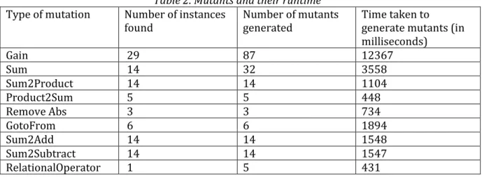
Table 2 (below) contains statistics collected when running the SIMUTATOR on the BBW Simulink-project. We report the type of mutation operator implementation selected, the number of
17
mutations created (mutants of the BBW Simulink system) and how much time it took for SIMUTATOR to create these mutations. Note that the time displayed only counts how much time it took to generate the mutations - it does not account for the time taken to copy the rather large system structure (folders and files of the BBW system). The result show that the number of mutants generated depends also on the type of mutation and not only on the number of instances found. In addition, the generation time takes between 12 (Gain) to 0.4 seconds (RelationalOperator). This demonstrates that this framework for mutation generation is rather efficient and easy to use, and thus contributing to achieving RG3.
Table 2. Mutants and their runtime Type of mutation Number of instances
found Number of mutants generated Time taken to generate mutants (in milliseconds) Gain 29 87 12367 Sum 14 32 3558 Sum2Product 14 14 1104 Product2Sum 5 5 448 Remove Abs 3 3 734 GotoFrom 6 6 1894 Sum2Add 14 14 1548 Sum2Subtract 14 14 1547 RelationalOperator 1 5 431
18
7.3
SIMPPAAL-integration
We used SIMPPAAL for model generation of the mutants generated by SIMUTATOR and we generated the UPPAAL-models. We found out that SIMPPAAL does not generate a complete UPPAAL model. To continue the integration, we needed to manually alter the UPPAAL model in order to prepare it for the integration with the MATS tool. Furthermore, as the modelling timed automata was out of the scope of this thesis, these modifications have been performed by the authors of SIMPPAAL and provided to the author of this thesis.
7.4
MATS-integration
The integration with the MATS tool has not worked as expected, but we achieved meaningful results. During the first evaluation of the tool we identified the following bug in the MATS tool: A test case consists of a set of input values and a set of expected output values. In MATS, the inputs were identified of type integer, while the BBW use case provided by Volvo GTT uses instead also variables of type double. After addressing this problem by fixing the bug in the MATS source code, we updated the tool, and MATS was used to generate test cases for the BBW use case.
Due to the time needed to make manual changes to the UPPAAL model, we have applied the MATS tool only on two mutated models, which were generated with the Product2Sum operator. We generated five test cases that were executed on each mutant. The tool needed to run for a rather long time to be able to return a result and evaluate these two tests. The tool stopped after 7101 seconds (around 2 hours). This shows that even for a few mutants, the execution of these tests can affect the scalability of using such an approach given the huge number of mutants created using SIMUTATOR.
7.5
Discussion
The obtained results could be useful for researchers, industrial practitioners, and tool developers. Regarding the mutation generation, the representation of a Simulink block might vary from one system to another. For example, when trying to transform Product blocks to Sum blocks, a naive approach was initially used and the block type was changed and we assumed that the default values for this new block would be sufficient. However, it turned out that this was not the case since the possible values in the Inputs-property differed from the ones found in Sum blocks (e.g., the Inputs-property in Product could contain the “/” and “*” signs, which of course would not be compiled properly in a block designed for “adding” and “subtraction” operations). We addressed this by implementing the altering of the Inputs-property in the new Sum-blocks such that it would not contain prohibited operators.
Another challenge in using SIMUTATOR for test execution appeared during the tool integration due to the model transformation from .mdl-files to .xml-models via SIMPPAAL. The issue here was that the files temp.mdl and test_sf_bsearch.mdl were part of the BBW project but not part of the actual system; they were not connected to any other models. This meant that the model transformation was applied to them but since they were not part of the system, the resulting model was identical to the reference model, which meant that these models were basically not mutated at all.
There are still some limitations that should be mentioned here related to the SIMUTATOR tool. The most obvious one is that users must add some parameters to the generated file(s) from the SIMUTATOR tool in order for these to be compatible with the other tools in the testing tool suite. Even though this was a known limitation even before the use of these tools, this is a challenge that needs to be considered when proposing such an approach.
19
8. Threats to validity
The following threats to validity were identified during the thesis:
• A literature review was performed but it was not systematic and some contributions could have been missed during the process. As the purpose of this study is not to systematically find mutation operators, the papers surveyed are sufficient for our purpose.
• The results of this thesis focused on one Simulink industrial system provide by Volvo GTT, so other possible issues might need to be taken into account when using a mutation framework on other systems. We argue that by using an industrial system, we provided a good-enough framework that can be used on other similar systems.
• Integration with other tools like SIMPPAAL and MATS can be a difficult task due to some changes in the xml files used by all tools that could change. Trying SIMUTATOR together with other tools can offer more insight on how to develop such an approach further.
9.
Conclusion and Future Work
In this thesis, we propose a mutation generation framework for Simulink by using a predefined set of mutation operators. Our method is supported by the tool SIMUTATOR, which we also introduce and apply on an industrial prototype named Brake-By-Wire system. This work enables the mutation analysis and testing of industrial Simulink models. In addition, we show how SIMUTATOR can be used together with SIMPAAL (a tool for transforming Simulink models to timed automata) and MATS (a tool for test generation) for mutation testing. The results show that SIMUTATOR is efficient and can be used successfully on industrial-sized Simulink software. The test generation and execution showed encouraging results but it is rather slow (around 2 hours for generating and evaluating several tests) even for a small number of mutations.
There are some possible future works related to this thesis. Our framework should be expanded to include even more possible mutations thus improving the generality of this approach. There is also a need to seamlessly integrate SIMUTATOR with a test execution framework for Simulink. In such a case, users would then be able to simply input the desired mutations and models and as a result obtain automatically mutated models, timed automata networks of the mutated models, run the tests and obtain a mutation score.
20
References
[1] P. Ammann, J. Offutt, and I. Version, “Introduction to Software Testing Edition 2 Paul Ammann and Jeff Offutt Instructor Version,” Cambridge Univ. Press, 2016.
[2] R. Just, D. Jalali, L. Inozemtseva, M. D. Ernst, R. Holmes, and G. Fraser, “Are mutants a valid substitute for real faults in software testing?,” Proc. 22nd ACM SIGSOFT Int. Symp. Found. Softw. Eng. - FSE 2014, pp. 654–665, 2014.
[3] R. F. Araujo, J. C. Maldonado, M. E. Delamaro, A. M. R. Vincenzi, and F. Delebecque, “Devising mutant operators for dynamic systems models by applying the HAZOP study,” ICSEA 2011, Sixth Int. Conf. Softw. Eng. Adv., no. c, pp. 58–64, 2011.
[4] M. Stephan, M. H. Alalfi, and J. R. Cordy, “Towards a taxonomy for Simulink model mutations,” Proc. - IEEE 7th Int. Conf. Softw. Testing, Verif. Valid. Work. ICSTW 2014, pp. 206–215, 2014.
[5] A. Brillout et al., “Mutation-based test case generation for simulink models,” Lect. Notes Comput. Sci. (including Subser. Lect. Notes Artif. Intell. Lect. Notes Bioinformatics), vol. 6286 LNCS, pp. 208–227, 2010.
[6] J. Larsson, R. Marinescu, and E. Enoiu, “Automatic Test Generation and Mutation Analysis using UPPAAL SMC,” 2017.
[7] P. Filipovikj, Pattern-based Specification and Formal Analysis of Embedded Systems Requirements and Behavioral Models, no. 256. Västerås, 2017.
[8] Y. Jia and M. Harman, “An Analysis and Survey of the Development of Mutation Testing,” Trans. Softw. Eng., vol. 37, no. 5, pp. 649–678, 2011.
[9] “SIMULINK: Simulation and Model-Based Design,” The MathWorks, Inc., 2018. [Online]. Available: https://se.mathworks.com/products/simulink.html. [Accessed: 08-Jan-2018]. [10] “Block Libraries - MATLAB & Simulink - MathWorks,” The MathWorks, Inc., 2018. [Online].
Available: https://se.mathworks.com/help/simulink/block-libraries.html. [Accessed: 08-Jan-2018].
[11] M. Utting, B. Legeard, A. Pretschner, and B. Legeard, “A Taxonomy of Model-Based Testing,” Softw. Testing, Verif. Reliab., vol. 22, no. April, pp. 297–312, 2006.
[12] L. Apfelbaum and J. Doyle, “Model Based Testing,” Procedings 10th Int. Softw. Qual. Week, pp. 1–14, 1997.
[13] Y. Zhan and J. a. Clark, “Search-based mutation testing for Simulink models,” Proc. 7th Annu. Conf. Genet. Evol. Comput., pp. 1061–1068, 2005.
[14] L. Thi My Hanh, K. Thanh, and N. T. B. Tung, “Mutation-based Test Data Generation for Simulink Models using Genetic Algorithm and Simulated Annealing,” no. July, 2014. [15] N. He, P. Rümmer, and D. Kroening, “Test-case generation for embedded simulink via
formal concept analysis,” Proc. 48th Des. Autom. Conf. - DAC ’11, p. 224, 2011.
[16] B. Liu, L. Lucia, S. Nejati, L. C. Briand, and T. Bruckmann, “Simulink Fault Localization : an Iterative Statistical Debugging Approach,” Softw. Test. Verif. Reliab., vol. 24, no. 8, pp. 591– 592, 2014.
[17] R. Matinnejad, S. Nejati, L. C. Briand, and T. Bruckmann, “SimCoTest: A Test Suite Generation Tool for Simulink/Stateflow Controllers,” Proc. 38th Int. Conf. Softw. Eng. Companion - ICSE ’16, vol. 1, pp. 585–588, 2016.
[18] R. Matinnejad, S. Nejati, L. C. Briand, and T. Bruckmann, “Automated Test Suite Generation for Time-Continuous Simulink Models,” 2015.
[19] P. Filipovikj, N. Mahmud, R. Marinescu, C. Seceleanu, O. Ljungkrantz, and H. Lönn,
“Simulink to UPPAAL statistical model checker: Analyzing automotive industrial systems,” Lect. Notes Comput. Sci. (including Subser. Lect. Notes Artif. Intell. Lect. Notes
Bioinformatics), vol. 9995 LNCS, no. Section 4, pp. 748–756, 2016.
[20] L. T. M. Hanh and N. T. Binh, “Mutation operators for simulink models,” Proc. - 4th Int. Conf. Knowl. Syst. Eng. KSE 2012, no. March 2016, pp. 54–59, 2012.
[21] B. K. Aichernig, F. Lorber, and D. Ničković, “Time for mutants - Model-based mutation testing with timed automata,” Lect. Notes Comput. Sci. (including Subser. Lect. Notes Artif. Intell. Lect. Notes Bioinformatics), vol. 7942 LNCS, pp. 20–38, 2013.
21
[22] Y. Jia and M. Harman, “Higher Order Mutation Testing,” Inf. Softw. Technol., vol. 51, no. 10, pp. 1379–1393, 2009.
[23] M. Harman, “Automated Test Data Generation using Search Based Software Engineering,” Proc. Second Int. Work. Autom. Softw. Test, vol. 30, no. 11, p. 2--, 2007.
[24] P. Mcminn, “Search-based software test data generation: A survey,” Softw. Testing, Verication Reliab., vol. 142, pp. 105–156, 2004.
[25] Y. Zhan and J. A. Clark, “Automatic test-data generation for testing simulink models,” Dep. Comput. Sci. Univ. York, vol. 9739, 2004.
[26] C. Kothari, Research methodology: methods and techniques. 2004.
[27] P. Filipovikj, N. Mahmud, R. Marinescu, C. Seceleanu, O. Ljungkrantz, and L. Henrik, “Analyzing Industrial Simulink Models by Statistical Model Checking,” pp. 1–33, 2017.