http://www.diva-portal.org
Postprint
This is the accepted version of a paper presented at EUROMECH-Colloqium 556 Theoretical,
Numerical, and xperimental Analysis in Wood Mechanics, 27 May – 29 May 2015, Dresden, Germany.
Citation for the original published paper: Briggert, A., Olsson, A., Oscarsson, J. (2015)
Modelling 3D orientation of knots in timber on the basis of dot laser scanning and the tracheid effect.
In: Josef Eberhardsteiner and Michael Kaliske (ed.),
N.B. When citing this work, cite the original published paper.
Permanent link to this version:
Modelling 3D orientation of knots in timber on the basis of
dot laser scanning and the tracheid effect
A. Briggert, A. Olsson and J. Oscarsson
Department of Building Technology Linnaeus University
SE-351 95 Växjö, Sweden E-mail: anders.olsson@lnu.se
1 Introduction
Ongoing research concerns the possibility of determining the 3D orientation of wood fibres within the entire volume of a wooden board using surface information from laser scanning. Previous research, Olsson and Oscarsson [1], has shown that the fibre orientation of side boards can be determined on the basis of such information. The present research is extended to also comprise boards cut from the centre of the log and a first step in this work is to establish 3D models of knots in boards on the basis of information from dot laser scanning of surfaces.
In comparison with other approaches aiming at 3D models of knots and wood fibre orientation, e.g. Guindos and Guaita [2] and Hackspiel et al. [3], the present model relies to a larger extent on the actual fibre orientation measured on each individual board, rather than on general assumption and mathematical models of typical fibre orientation alone.
The fact that all data needed for the model can be sampled in sawmill production speed means that developed models could be used as a basis for advanced strength grading methods, for grading with respect to shape stability and for other purposes of industrial interest.
2 Modelling assumptions and examples of preliminary results
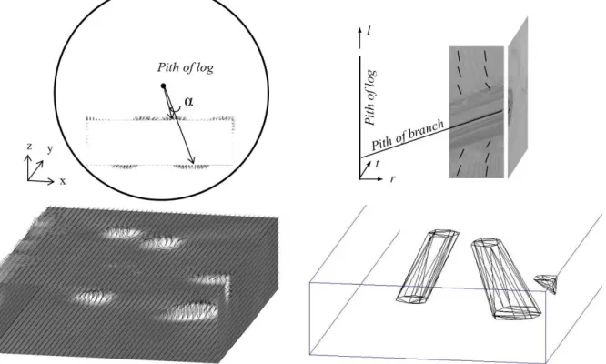
When the light of a dot laser falls on a surface of softwood it will spread more in the direction of the tracheid than across and thus an elliptically shaped light spot, rather than a circular one, can normally be observed on the surface. This effect is referred to as the tracheid effect. The major axis of the ellipse point out the local direction of the fibres in the plane of the surface and the ratio between the two axes gives an indication of the diving angle. A ratio value approaching one (1) indicates that the fibre direction is virtually perpendicular to the observed surface, Simonaho et al. [4]. However, the tracheid effect does not capture the fact that some fibres in the vicinity of knots are oriented such that they integrate with the knot while others go around the knot. Therefore, information obtained from scanning should be combined with general knowledge of how fibres integrate with and pass around knots in timber. An example of how limited information from scanning can be used in combination with general knowledge of wood is illustrated to the upper right in Figure 1. Though scanning of the surface to the very right would give no information on the direction of the diving angle, but only on the magnitude of it, we know that fibres below and above a knot, respectively, in that plane must be oriented as indicated by the short black lines drawn on the adjoining surface. Since the tracheid effect points out where the fibre direction deviates substantially from the direction of the board, knots on wood surfaces can rather easily be identified, see the lower
left picture of Figure 1. Wherever the 3D fibre orientation, determined on the basis of both the fibre orientation projected on the investigated surface and on the diving angle, has an angle to the pith of the log from which the board is cut that exceeds some threshold value, it is concluded that it is a surface of a knot. Furthermore it can be decided whether knots observed on different surfaces are parts of the same knot or not. If they have, with some suitable tolerance, the same coordinate in the main direction of the board and also about the same polar coordinate α, see the upper left part of Figure 1, it is concluded that they are parts of the same knot. The lower right picture of Figure 1 shows knots in 3D thus identified.
Fig. 1 Knots identified on the board surfaces (lower left), knot identification using the tangential coordinate α (upper left), 3D visualization of knots (lower right), and correct fibre orientation with respect to pith location in log and branch (upper right).
References
[1] Olsson, A. and Oscarsson, J. Three dimensional fibre orientation models for wood based
on laser scanning and the tracheid effect, in: Proceedings of the 2014 World Conference
on Timber Engineering, Quebec, Canada, 2014.
[2] Guindos, P. and Guaita, M. A three-dimensional wood material model to simulate the
behavior of wood with any type of knot at the macro-scale. Wood Science and
Technology, 47:585-599, 2013.
[3] Hackspiel, C., de Borst, K. and Lukacevic, M. A numerical simulation tool for wood grading model development. Wood Science and Technology, 48(5):633-649, 2014. [4] Simonaho, S.-P., Palviainen, J., Tolonen, Y. and Silvennoinen, R. Determination of wood
grain direction from laser light scattering pattern. Optics and Lasers in Engineering,