Performance Evaluation of Embedded Microcomputers for Avionics Applications
147
0
0
Full text
(2) Performance Evaluation of Embedded Microcomputers for Avionics Applications. Celal Can Bilen John Alcalde González. This thesis work is performed at Jönköping Institute of Technology within the subject area Computer and Electrical Engineering. The work is part of the master’s degree. The authors are responsible for the given opinions, conclusions and results. Handledare: Torbjörn Månefjord Lars Aggestig Prof. Shashi Kumar Examiner:. Prof. Shashi Kumar. Credit points: 30 hp (D-level) Date: Archive number:.
(3) Förord. Förord Vi skulle vilja tacka alla som gjort det möjligt att genomföra detta examensarbete, framförallt våra handladere, Professor Sashi Kumar för hans underbara uppsikt, rådgivning samt ledning av detta projekt, särskilt med akademiska teman; Torbjörn Månefjord för att han gett oss tillfället att arbeta med ett sådant projekt på SAAB samt hans tro på oss från början av projektet; Lars Aggestig för hans ständiga stöd och hjälp under projektets praktiska moment samt för hans synpunkter. Vi skulle också vilja tacka Helené Olsson och Anita Karlsson från SAAB Avitronics för all deras vägledning angående projektförvaltningen. Vi skulle vilja tacka dem alla för deras värdefulla ideer och diskussioner angående projektet, genom detta har vi breddat vår kunskap. Vi är glada över att ha fått möjligheten att genomföra detta projekt på ett sådant ansett företag som SAAB. Celal Can Bilen & John Alcalde Gonzalez Förutom ovärderligt stöd och ledning av dem som har nämnats, skulle vi också personligen vilja tacka följande: Professor Alf Johansson för att han har introducerat mig i den häpnadsväckande världen av inbygdda ”underverk”; Assisterande Professor Ilja Belov för sin förståelse och ständiga stöd innan projektet; Professor Hamit Serbest för att han visat mig hur man blir en ”riktig” ingenjör; Assisterande Professor Ulus Cevik för att han gett mig möjligheten att komma till mitt andra hemland, Sverige. Vill även tacka min kära familj: min far Atilla Bilen för att han “sparkat iväg mig” till svenskt land, min syster Spec. Dr. Aysegül Bilen för att hon alltid uppmuntrat och stöttat mig, och min kära mor Selma Bilen för att hon alltid ”puffat” mig till mina begränsningar, oavsett när eller vad för, och aldrig låtit mig falla till marken. Jag kommer aldrig att kunna återbetala ert omätliga stöd... Jag skulle vilja tillägna detta examensarbete till min mormor, Kurultay Agackanli som förutsåg att mina drömmar skulle förverkligas och min morfar Celal Agackanli som arbetade i Sverige på 60-talet och delade med sig till mig av sin stora kunskap, tyvärr hann jag aldrig lära känna honom så väl. Jag är jätteglad och stolt över att ha genomfört mitt examensarbete inom avancerad datorarkitektur, genom detta har jag fått tillfället att fortsätta min familjtradition av teknik, särskilt arkitektur, för båda mina föräldrar är arkitekter. Jag är ytterligare glad över att ha fullgjort deras drömmar när de var unga, att ta masterexamen inom arkitektur, tyvärr hann de inte då. Ljusen kommer aldrig att slockna! Celal Can Bilen. i.
(4) Acknowledgements. Acknowledgements We would like to thank to our supervisors, Prof. Sashi Kumar, from Jönköping Institute of Technology, for his wonderful supervision and feedback during the thesis as well as his help and support, especially about academic issues; Torbjörn Månefjord, from SAAB Avitronics, for giving us the opportunity to work in such a project and his trust on us since the beginning of the project; and Lars Aggestig, also from SAAB Avitronics, for his continuous support and help especially during the practical stages of the project, whenever we had question marks in our heads. We would also like to thank Anita Karlsson and Helene Olsson from SAAB Avitronics for all their guidance and support regarding project administration issues. We would like to thank them all for their invaluable ideas and discussions regarding the project and their influence on broadening our knowledge and insight. We feel blessed to have carried out such a wonderful thesis project at an eminent company like SAAB. Celal Can Bilen & John Alcalde Gonzalez In addition to the invaluable support and guidance of the people mentioned, we would like to thank also personally to: Prof. Alf Johansson for introducing me the amazing world of embedded wonders; Assist. Prof. Ilja Belov for always supporting us, even before the start of the project; Prof. Hamit Serbest for showing me how to be a “real” engineer; Assist. Prof. Ulus Cevik for giving me the opportunity to come my second home country, Sweden, and his guidance off the studies. I would also like to thank my dear family; my father Atilla Bilen for “kicking” me towards the Swedish land, my sister Aysegul Bilen for always cheering me up and supporting me, and my dear mother Selma Bilen, for always “pushing” me to my limits, no matter when and what, and never letting me touch to the ground. I will never be able to pay back your immeasurable support. I would like to dedicate this thesis to my grandmother, Kurultay Agackanli, who foretold me about my dreams come true, and my grandfather Celal Agackanli, who worked in Sweden during the 60s and fed me with his broad knowledge, unfortunately I did not have the chance to get to know him much... The lightswill never go out! Celal Can Bilen. ii.
(5) Abstract. Abstract Embedded microcomputers are used in a wide range of applications nowadays. Avionics is one of these areas and requires extra attention regarding reliability and determinism. Thus, these issues should also be born in mind in addition to performance while evaluating embedded microcomputers. This master thesis suggests a framework for performance evaluation of two members of the PowerPC microprocessor family, namely the MPC5554 from Freescale and the PPC440EPx from AMCC, and analyzes the results within and between these processors. The framework can be generalized to be used in any microprocessor family, if necessary. Apart from performance evaluation, this thesis also suggests a new terminology by introducing the concept of determinism levels to be able to estimate determinism issues in avionics applications more clearly, which is crucial regarding the requirements and working conditions of this very application. Such estimation does not include any practical results as in performance evaluation, but rather remains theoretical. Similar to Automark™ used by AutoBench™ in the EEMBC Benchmark Suite, we introduce a new performance metric score that we call ”Aviomark”, and we carry out a detailed comparison of Aviomark with the traditional Automark™ score to be able to see how Aviomark differs from Automark™ in behavior. Finally, we have developed a graphical user interface (GUI) which works in parallel with the Green Hills MULTI ® Integrated Development Environment (IDE) in order to simplify and automate the performance evaluation process. By the help of the GUI, the users will be able to easily evaluate their specific PowerPC processors by starting the debugging from MULTI IDE.. Keywords: Microprocessor, Avionics, PowerPC, Performance Evaluation, Determinism, Automark™ , Aviomark, EEMBC, Green Hills MULTI, IDE, GUI. iii.
(6) Sammanfattning. Sammanfattning Inbyggda mikrodatorer används numera i ett brett spektrum av applikationer. Avionik är ett av dessa områden samt kräver extra uppmärksamhet när det gäller tillförlitlighet samt determinismämnen. Därför bör man beakta dessa ämnen utöver prestanda vid utvärdering av inbyggda mikrodatorer. Detta examensarbete föreslår en inramning för prestandautvärdering av två medlemmar av PowerPC mikroprocessor familjen, nämligen MPC5554 från Freescale och PPC440EPx från AMCC, samt analyserar resultaten inom och mellan dessa processorer. Imramningen kan generaliseras till att användas i någon mikroprocessor familj vid behov. Utöver prestandautvärdering, så föreslår det här examensarbetet också en ny terminologi, genom att införa begreppet om determinism nivåer för att kunna uppskatta determinismfrågor i flygelektronik applikationer tydligare, vilket får avgörande betydelse när det gäller krav och arbetsförhållanden för just denna applikation. Sådan uppskattning ingår inte några praktiska resultat som i utvärdering av prestanda, utan det är snarare teoretiska. Liksom Automark™ som används av Autobench™ i EEMBC Benchmark Suite, introducerar vi en ny prestandamått, som vi kallar "Aviomark", och utför en detaljerad jämförelse av Aviomark med traditionella Automark™ betygpoäng för att kunna se hur Aviomark skiljer sig från Automark™ beteende. Slutligen har vi utvecklat ett grafiskt användargränssnitt (GUI) som fungerar parallellt med Green Hills MULTI ® Integrerad Utvecklingsmiljö (IDE) för att simplifiera och automatisera utvärderingsprocessen. Med hjälp av detta program kommer användarna enkelt att kunna utvärdera sina speciella PowerPC processorer genom att starta debugging från MULTI IDE.. Nyckelord: Mikroprocessor, Avionik, PowerPC, Prestandautvärdering, Tillförlitlighet, Automark™ , Aviomark, EEMBC, Green Hills MULTI, IDE, GUI. iv.
(7) Table of Contents. Table of Contents Förord................................................................................................ i Acknowledgements............................................................................ ii Abstract ............................................................................................ iii Sammanfattning ............................................................................... iv List of Figures................................................................................. viii List of Tables..................................................................................... x List of Abbreviations......................................................................... xi 1. Introduction................................................................................ 1 1.1. BACKGROUND .................................................................................................................. 1 1.2. EMBEDDED SYSTEMS......................................................................................................... 1 1.2.1. Debugging..................................................................................................................... 2 1.2.2. BIOS vs. Boot loaders..................................................................................................... 3 1.3. AVIONICS.......................................................................................................................... 4 1.4. EMBEDDED SYSTEMS IN AVIONICS ..................................................................................... 5 1.4.1. Functionalities............................................................................................................... 5 1.4.2. Determinism.................................................................................................................. 6 1.4.3. Timing......................................................................................................................... 6 1.4.4. Reliability ..................................................................................................................... 7 1.4.5. Radiation...................................................................................................................... 7 1.5. H ARDWARE ARCHITECTURE SCHEME FOR AVIONICS EMBEDDED SYSTEM S .......................... 8 1.5.1. CPU............................................................................................................................. 8 1.5.2. Primary Memory............................................................................................................ 8 1.5.3. Non-volatile Memory...................................................................................................... 8 1.5.4. Parameter RAM (PRAM) ............................................................................................... 9 1.5.5. Communication Interfaces............................................................................................... 9 1.6. T HESIS OBJECTIVES........................................................................................................... 9 1.7. T HESIS SCOPE ................................................................................................................. 10 1.8. T HESIS LAYOUT ............................................................................................................... 10. 2. Embedded Microprocessors and Memories................................. 12 2.1. CPU ............................................................................................................................... 12 2.2. CLOCK SPEED ................................................................................................................. 13 2.3. M ICROARCHITECTURE .................................................................................................... 14 2.3.1. Superpipeline vs. Superscalar.......................................................................................... 14 2.3.2. Look-ahead Execution................................................................................................... 15 2.3.3. Out-of-Order-Execution (OOOE) .................................................................................. 16 2.3.4. Speculation.................................................................................................................. 18 2.3.5. Branch Prediction ........................................................................................................ 19 2.3.6. Prefetching.................................................................................................................. 22 2.4. FLOATING POINT ............................................................................................................ 23 2.5. M EMORY H IERARCHY...................................................................................................... 23 2.6. CACHE M EM ORY............................................................................................................. 25 2.6.1. Line Size..................................................................................................................... 27 2.6.2. Cache Size................................................................................................................... 27 2.6.3. Associativity................................................................................................................. 28 2.6.4. Early Restart & Critical Word First ................................................................................ 29 2.6.5. Non-blocking Caches.................................................................................................... 29 2.6.6. Multi-level Caches........................................................................................................ 30 2.6.7. Simple and Small Caches.............................................................................................. 31 2.6.8. Unified vs. Separate Caches........................................................................................... 31. v.
(8) Table of Contents 2.6.9. Write Policy................................................................................................................. 32 2.6.10. Allocation Policy...................................................................................................... 33 2.6.11. Write Buffers........................................................................................................... 33 2.6.12. Replacement Policy................................................................................................... 35 2.6.13. Cache Locking......................................................................................................... 36 2.7. VIRTUAL M EM ORY (VM) ................................................................................................. 37 2.8. M EMORY T ECHNOLOGIES ............................................................................................... 39 2.8.1. VolatileMemory .......................................................................................................... 39 2.8.2. Non-volatile Memory.................................................................................................... 44 2.8.3. Memory TechnologiesTimeline...................................................................................... 47 2.9. POWERPC....................................................................................................................... 48 2.9.1. Background ................................................................................................................. 48 2.9.2. Architecture................................................................................................................. 49 2.9.3. The PPC440EPx and MPC5554 in Real Life................................................................. 52 2.9.4. PowerPC Timeline....................................................................................................... 53. 3. Benchmarking and Performance Evaluation ............................... 54 3.1. BACKGROUND ................................................................................................................ 54 3.2. CLASSICAL BENCHMARKS................................................................................................. 55 3.2.1. Whetstone................................................................................................................... 55 3.2.2. Dhrystone.................................................................................................................... 56 3.2.3. SPEC Benchmarks....................................................................................................... 57 3.2.4. EEMBC Benchmarks.................................................................................................... 57 3.2.5. MiBench..................................................................................................................... 58 3.3. COREM ARK™ ................................................................................................................ 58 3.4. PERFORMANCE EVALUATION M ETRICS............................................................................. 59 3.4.1. Classical Metrics........................................................................................................... 59 3.4.2. Arithmetic and Geometric Performance Mean.................................................................. 60 3.4.3. Iterationsper Second and Total Run Time....................................................................... 61 3.5. RELATED W ORK .............................................................................................................. 62. 4. Methodology............................................................................. 63 4.1. H ARDWARE CONFIGURATION .......................................................................................... 63 4.2. SOFTWARE T OOLS........................................................................................................... 63 4.2.1. MULTI Environment................................................................................................... 63 4.2.2. Benchmarks................................................................................................................. 64 4.2.3. GUI ........................................................................................................................... 65 4.3. T ASKS FOR EVALUATION OF A BOARD ............................................................................... 66 4.4. T HE M ETHODOLOGY FOR BOARD EVALUATION ............................................................... 66 4.5. I LLUSTRATIVE EXAMPLES ................................................................................................. 69 4.5.1. Script Files: “.rc”.......................................................................................................... 69 4.5.2. Setup Files: “.mbs”........................................................................................................ 69 4.5.3. MULTI output files: “.txt” ............................................................................................ 71. 5. Results...................................................................................... 72 5.1. AMCC PPC440EPX........................................................................................................ 72 5.1.1. Performance Parameters................................................................................................ 72 5.1.2. Configurations............................................................................................................. 74 5.1.3. Determinism................................................................................................................ 74 5.1.4. Performance................................................................................................................ 78 5.2. FREESCALE MPC5554 ..................................................................................................... 91 5.2.1. Performance Parameters................................................................................................ 92 5.2.2. Determinism................................................................................................................ 94 5.2.3. Performance................................................................................................................ 96 5.2.4. Effect of Memory Technology: SRAM vs. FLASH............................................................ 106. 6. Conclusions and Future Work ................................................. 108 6.1. 6.2.. CONCLUSIONS.............................................................................................................. 108 CONTRIBUTIONS........................................................................................................... 109. vi.
(9) Table of Contents 6.3.. FUTURE WORK ............................................................................................................. 109. References..................................................................................... 111 Appendix A: Processor Architecture Comparison ............................ 120 Appendix B: Processor Register Maps............................................. 124 Appendix C: EEMBC AutoBench™ Algorithms............................. 126 Appendix D: GUI Manual ............................................................. 129. vii.
(10) List of Figures. List of Figures FIGURE 1-1: INTERACTION OF ROM, RAM AND I/O WITH THE CPU IN EMBEDDED SYSTEM FIGURE 1-2: A TYPICAL CPU BOARD FOR AVIONIC APPLICATIONS (SOURCE: SAAB AVITRONICS) FIGURE 2-1: GENERAL STRUCTURE OF OOOE MECHANISM WITH ROB FIGURE 2-2: CENTRALIZED (A) VS. DECENTRALIZED (B) RESERVATION STATIONS FIGURE 2-3: MEMORY HIERARCHY FIGURE 2-4: 128 KB TWO-WAY SET-ASSOCIATIVE CACHE FIGURE 2-5: HIT UNDER MISS FIGURE 2-6: UNIFIED (TO THE LEFT) AND SEPARATE (TO THE RIGHT) CACHE ARCHITECTURES FIGURE 2-7: DATA MOVEMENT IN THE MEMORY HIERARCHY, INCLUDING THE VIRTUAL MEMORY FIGURE 2-8: SRAM WRITE OPERATION FIGURE 2-9: FLOW-THROUGH VS. PIPELINED SSRAM READ FIGURE 2-10: DRAM READ AND WRITE OPERATION FIGURE 2-11: FOUR-WORD SDRAM BURST WRITE WITH DQM DISABLE & DQM MASKING FIGURE 2-12: MEMORY TECHNOLOGIES TIMELINE FIGURE 2-13: POWERPC ARCHITECTURE FIGURE 2-14: POWERPC TIMELINE FIGURE 4-1: HARDWARE CONFIGURATION OF THE PROJECT FIGURE 4-2: GUI FOR FILE MANAGEMENT FIGURE 4-3: TASKS FOR EVALUATION OF A BOARD FIGURE 4-4: PROPOSED METHODOLOGY FOR BOARD EVALUATION (INFORMAL UML FORMAT) FIGURE 5-1: DETERMINISM LEVELS IN PPC440EPX FIGURE 5-2: EFFECT OF CLOCK FREQUENCY (AUTOMARK™ ) FIGURE 5-3: EFFECT OF CACHE LOCKING IN WRITE-THROUGH CASE (AUTOMARK™ ) FIGURE 5-4: EFFECT OF CACHE LOCKING IN COPY-BACK CASE (AUTOMARK™ ) FIGURE 5-5: HARDWARE VS. SOFTWARE FP (AUTOMARK™ 666/166 MHZ) FIGURE 5-6: HARDWARE VS. SOFTWARE FP PERCENTAGE COMPARISON (AUTOMARK™ 666/166MHZ) FIGURE 5-7: EFFECT OF CLOCK FREQUENCY (AVIOMARK HIGHL) FIGURE 5-8: EFFECT OF CACHE LOCKING IN THE WRITE-THROUGH CASE (AVIOMARK HIGHL) FIGURE 5-9: EFFECT OF CACHE LOCKING IN THE COPY-BACK CASE (AVIOMARK HIGHL) FIGURE 5-10: HARDWARE VS. SOFTWARE FP (AVIOMARK HIGHL 666/166 MHZ) FIGURE 5-11: HARDWARE VS. SOFTWARE FP PERCENTAGE COMPARISON FIGURE 5-12: EFFECT OF CLOCK FREQUENCY (AVIOMARK MOTORC) FIGURE 5-13: EFFECT OF CACHE LOCKING IN WRITE-THROUGH CASE (AVIOMARK MOTORC) FIGURE 5-14: EFFECT OF CACHE LOCKING IN COPY-BACK CASE (AVIOMARK MOTORC) FIGURE 5-15: HARDWARE VS. SOFTWARE FP (AVIOMARK MOTORC 666/166 MHZ) FIGURE 5-16: HARDWARE VS. SOFTWARE FP PERCENTAGE COMPARISON FIGURE 5-17: PERCENTAGE OF PERFORMANCE LOSSWITH SOFTWARE FP FIGURE 5-18: HARDWARE VS. SOFTWARE FP (FOR BASIC FLOATING POINT ALGORITHM) FIGURE 5-19: AVIOMARK VS . AUTOMARK™ (533 MHZ CLOCK AND 133 MHZ BUS FREQUENCY) FIGURE 5-20: AVIOMARK VS. AUTOMARK™ (666 MHZ CLOCK AND 166 MHZ BUS FREQUENCY) FIGURE 5-21: AVIOMARK VS. AUTOMARK™ FOR CACHE LOCKING IN THE WRITETHROUGH CASE FIGURE 5-22: AVIOMARK VS. AUTOMARK™ FOR CACHE LOCKING IN THE COPY-BACK CASE FIGURE 5-23: RELATIVE PERFORMANCE LOSS OF THE THREE MAIN CONFIGURATIONS WITH SOFTWARE FP FIGURE 5-24: PPC440EPX CONFIGURATIONS FROM LOWEST TO HIGHEST PERFORMANCE (AUTOMARK™ 666/166 MHZ) FIGURE 5-25: DETERMINISM LEVELS IN MPC5554. viii. 4 9 17 17 24 29 30 32 39 40 41 41 42 47 50 53 63 65 67 68 77 78 78 79 80 80 81 81 82 83 83 84 84 84 85 86 86 87 87 88 88 89 89 90 95.
(11) List of Figures FIGURE 5-26: INCREASE OF PERFORMANCE WITH BUFFERS, STREAMING AND BTB (AUTOMARK™ ) FIGURE 5-27: A DETAILED LOOK INTO THE EFFECT OF BUFFERS AND BTB BY USING THE FIGURE 5-28: A DETAILED LOOK INTO THE EFFECT OF BUFFERS AND BTB BY USING AUTOMARK™ GRADES AS A PERCENTAGE COMPARED TO THE HIGHEST PERFORMANCE CONFIGURATION FIGURE 5-29: INCREASE OF PERFORMANCE WITH BUFFERS, STREAMING AND BTB FIGURE 5-30: INCREASE OF PERFORMANCE WITH BUFFERS, STREAMING AND BTB FIGURE 5-31: A DETAILED LOOK INTO THE EFFECT OF BUFFERS AND BTB BY USING THE AVIOMARK HIGHL GRADES FIGURE 5-32: A DETAILED LOOK INTO THE EFFECT OF BUFFERS AND BTB BY USING AVIOMARK HIGHL GRADES AS A PERCENTAGE COMPARED TO THE HIGHEST PERFORMANCE CONFIGURATION FIGURE 5-33: A DETAILED LOOK INTO THE EFFECT OF BUFFERS AND BTB BY USING THE FIGURE 5-34: A DETAILED LOOK INTO THE EFFECT OF BUFFERS AND BTB BY USING AVIOMARK MOTORC GRADES AS A PERCENTAGE COMPARED TO THE HIGHEST PERFORMANCE CONFIGURATION FIGURE 5-35: AUTOMARK™ AND AVIOMARK COMPARISON OF THE TWO BEST AND THE WORST CONFIGURATIONS IN MPC5554 FIGURE 5-36: PERFORMANCE COMPARISON IN PERCENTAGE BETWEEN AUTOMARK™ AND AVIOMARK FIGURE 5-37: MPC5554 VS. PPC440EPX PERFORMANCE COMPARISON (AUTOMARK™ ) FIGURE 5-38: MPC5554 VS. PPC440EPX PERFORMANCE COMPARISON IN PERCENTAGE FIGURE 5-39: MPC5554 VS. PPC440EPX PERFORMANCE COMPARISON (AVIOMARK HIGHL) FIGURE 5-40: MPC5554 VS. PPC440EPX PERFORMANCE COMPARISON IN PERCENTAGE (AVIOMARK HIGHL) FIGURE 5-41: MPC5554 VS. PPC440EPX PERFORMANCE COMPARISON (AVIOMARK HIGHL) FIGURE 5-42: MPC5554 VS. PPC440EPX PERFORMANCE COMPARISON IN PERCENTAGE FIGURE 5-43: FLASH VS. SRAM IN BASIC FLOATING POINT (AUTOMARK™ ) FIGURE 5-44: FLASH VS. SRAM IN BIT MANIPULATION (AUTOMARK™ ) FIGURE 5-45: RATIO OF PERFORMANCE OF SRAM TO THE FLASH (AUTOMARK™ ) FIGURE 6-1: PPC440EPX CONFIGURATION SUMMARY AND AUTOMARK™ RESULTS FIGURE 6-2: MPC5554 CONFIGURATION SUMMARY AND AUTOMARK™ RESULTS. ix. 96 97 97 98 98 99 99 99 100 102 102 103 103 104 104 105 105 106 107 107 108 108.
(12) List of Tables. List of Tables. TABLE 1: COMPARISON OF WELL-KNOWN AVIONICS DATA BUSES TABLE 2: CONFIGURATION SCRIPTS FOR THE AMCC PPC440EPX PROCESSOR TABLE 3: CONFIGURATION SCRIPTS FOR THE FREESCALE MPC5554 PROCESSOR. x. 5 75 91.
(13) List of Abbreviations. List of Abbreviations (In chronological order). Abbreviation. Meaning. GUI. Graphical User Interface Integrated Development Environment Reduced Instruction Set Computer Very Long Instruction Width Operating System Joint Test Action Group Real Time Operating System Read-Only Memory Random Access Memory Synchronous Dynamic Random Access Memory Central Processing Unit Full Authority Digital Electronics Controls Military Standard Department of Defense Standard European Organization for Civil Aviation Equipment European Network of Transmission System Operators Aeronautical Radio Inc. Mean Time Between Failures Single Even Upset Single Event Functional Interrupts Error Correction Coding Dynamic Random Access Memory Parameter Random Access Memory Input / Output Controller Area Network Serial Peripheral Interface Floating Point Unit Inter-Integrated Circuit Auxiliary Processing Unit Phase-Locked Loop Peripheral Component Interconnect Direct Memory Access Instruction Level Parallelism Out-of-Order Execution. IDE RISC VLIW OS JTAG RTOS ROM RAM SDRAM CPU FADEC M IL-STD DOD-STD EUROCAE ETSO ARINC M TBF SEU SEFI ECC DRAM PRAM I/O CAN SPI FPU I 2C APU PLL PCI DM A ILP OOOE xi.
(14) List of Abbreviations. Abbreviation. Meaning. ILW RS RAW WAW ROB IPC TLB NOP IU BPU BPB BTAC BTB BH T. Instruction Look-ahead Window Reservation Station Read-After-Write Write-After-Write Reorder Buffer Instructions per Cycle Translation Look-ahead Buffer No-Operation Instruction Unit Branch Processing Unit Branch Prediction Buffer Branch Target Address Cache Branch Target Buffer Branch History Table Institute of Electrical and Electronics Engineers Static Random Access Memory (RAM) Dynamic RAM Memory Management Unit Average Memory Access Time Clocks per Instruction First-In-First-Out Most Recently Used Least Recently Used Pseudo-Least Recently Used Virtual Memory Write Enable Error Correction Programmable ROM Erasable PROM Synchronous DRAM Synchronous SRAM Row Address Strobe Column Address Strobe Clock Enable Auto Pre-charge Activate Read Column Address Strobe Latency One-Time-Programmable ROM Universal Asynchronous Receiver Transmitter. IEEE SRAM DRAM MMU AM AT CPI FIFO M RU LRU PLRU VM WE EC PROM EPROM SDRAM SSRAM RAS CAS CKE AP ACTV RD CL OTP ROM UART xii.
(15) List of Abbreviations. Abbreviation. Meaning. M OS EEPROM /E2PROM. Metal Oxide Semiconductor Electrically Erasable PROM Embedded Microprocessor Benchmark Consortium Worst Case Execution Time Mega Instructions per Second Whetstone Instructions per Second Dhrystone Mega Instructions per Second Standard Performance Evaluation Corporation Clock Time Clock Cycle Clock per Instruction Mega Floating Point Instructions per Second Write-Through Copy-Back Store Without Allocate Processor Local Bus Instruction Cache Controller Data Cache Controller Interrupt Service Routine Floating Point Avionics Benchmark Motor Control High Lift Power PC Applied Micro-Circuits Corporation Reduced Apple-IBM-Motorola Execution Unit Floating Point Register General Purpose Register Floating Point Status Control Register American National Standards Institute Instruction Queue Completion Uniy Core Interface Unit Bus Interface Unit Load – Store Unit. EEM BC WCET M IPS WIPS DM IPS SPEC CT CC CPI M FLOPS WT CB SWOA PLB ICC DCC ISR FP Aviomark M otorC H ighL PPC AM CC RSC AIM EU FPR GPR FPSCR ANSI IQ CU CIU BIU LSU xiii.
(16) List of Abbreviations. Abbreviation. Meaning. DFLB IFLB LM Q DDI. Data Line Fill Buffer Instruction Line Fill Buffer Load Miss Queue Direct Diesel Injection Redundant Array of Inexpensive Disks Gasoline Direct Injection. RAID GDI. xiv.
(17) Introduction. 1. Introduction 1.1. Background The increasing levels of complexity and concurrency in microprocessors have resulted in growing demand for performance evaluation apart from the traditional functional testing. In earlier designs, performance validation requirements were minimal due to relatively simple micro-architectures, most of which were von-Neumann models. However, it is nowadays common among modern superscalar microarchitectures to see more advanced and complex features such as multiple instruction dispatch and out–of–order, pipelined execution. Most of these microarchitectures support speculative execution, based on branch prediction. The presence of (multi–level) cache misses is even more difficult to account for. Thus, predicting the correct (expected) execution time for even a simple test case can be quite difficult. These have all made performance testing more challenging but at the same time more valuable to system engineers, both at the hardware and software level. SAAB Avitronics in Jönköping is a leading supplier of Avionics and Electronic Warfare Systems and it has been developing and integrating avionics for both military and commercial aircrafts, with a full spectrum of modular avionics and mechanical systems with a wide range of products, mainly for avionic applications, including e.g. utility and mission computers, control computers, hydraulic actuators, electric motors and motor controllers. Many of these products include embedded microcomputers. This thesis work has been carried out under supervision and guidance of “Centre of Excellence: Computers” department of SAAB Avitronics in Jönköping, which is a centralized resource for computer design within SAAB Avitronics and SAAB.. 1.2. Embedded Systems Embedded systems are special-purpose computer systems with a combination of computer hardware and software, designed especially for target applications. In contrast to general-purpose computers which run multiple tasks, embedded systems perform only a narrow range of pre-defined tasks [1]. Their name comes from being usually embedded as part of a larger complete device including hardware and they are not directly visible to users [2]. Embedded systems are tightly constrained by design metrics such as cost, size, performance and power [2]. They can employ general-purpose, applicationspecific or single-purpose processors depending on the application being used. They are often resource-limited e.g. they employ no hard drives, may have power limitations, run built-in application-specific software instead of user selected programs and the hardware/software is pre-integrated for usage in the target applications without human intervention. In contrast to general-purpose computers which use just a very few processor architectures, fairly large number of basic CPU microarchitectures are used in embedded systems. ARM and x86 have been the most frequently deployed, each at roughly 30 percent as well as PowerPC and M IPS with fairly smaller shares [1]. 1.
(18) Introduction. They implement Von Neumann or Harvard architectures, RISC as well as non-RISC or VLIW. Typical word lengths vary from 4-bits to 64-bits and beyond (128 bits in the new generation of processors) although the most typical ones are 32/64 bits wide. Some embedded systems include an embedded operating system (OS), which can either be a very small OS that was developed specifically for use with embedded systems, or it can be a stripped down version of system that is commonly used on general-purpose computers [1]. If the application intended for the embedded system requires real-time constraints, then a real-time operating system (RTOS) is used. Popular embedded RTOS in the market today are Embedded Linux, LynxOS, OS-9, OSE, VxWorks, Windows CE and Windows XP Embedded. Many embedded systems are so specialized, however, that they do not require any need for operating system since the whole logic can be implemented as a single program code stored in memory. Many embedded systems are safety-critical and therefore have to be dependable. Avionics is an example of extremely safety-critical systems at least partially controlled by software. Dependability covers reliability (probability that a system will not fail), maintainability (probability that a failing system can be repaired within a certain time period), availability (probability that system is available), safety (property that a failing system not cause any harm) and security (property that confidential data remains confidential) [3]. Most embedded systems require real-time response and they usually have real-time constraints to achieve these issues. They form the basis of so-called postPC era, where information processing is moving away from PCs to embedded systems. 1.2.1.. Debugging. Debugging is the process of identifying the root cause of an error and correcting it by simulating the target device i.e. the embedded microcomputer board, and running it on a host computer [5]. The findings from VDC's 2005 Embedded Systems Market Statistics report [6] indicate that approximately 40% of embedded development projects run behind schedule. Debugging is generally accepted as the most time consuming and costly phase of the development process with some estimates putting the debug cost as high as 50% of the total development cost [5]. Three main debugging techniques have emerged in attempt to address these limitations [6]. These are: ROM M onitor : A piece of code executes on the target system where the Debugger running on the host PC communicates via a dedicated port on the target and sends commands to monitor the debugging process and returns response from the target system. In-Circuit Emulator (ICE): ICE replaces the target’s microcontroller incircuit and emulates its functionality by providing full visibility into the inside of the “emulated” microcontroller, which is connected to the host PC and typically controlled by a Debugger as in ROM monitor.. 2.
(19) Introduction. On-Chip Debug: Because of the costs of ICEs, semiconductor vendors have started integrating dedicated debugging hardware into their chips. The onchip debug circuitry typically interfaces to the outside world through a JTAG interface which is the most popular standard used. The user’s PC interfaces to the target via a JTAG emulator connected to the host PC. On-chip debugging can offer run-time control functionality including program download, go/step/halt, memory/register access and breakpoints [6]. Recent implementations of on-chip debug have also started to offer real-time trace functionality. In our project, we are using the Green H ills SuperTrace™ probe which features real-time trace functionality. 1.2.2.. BIOS vs. Boot loaders. When power is first applied to a PC, a software program called BI OS (Basic I/O Software) immediately takes control of the processor. BIOS is a complex set of system configuration software routines that have low-level details of the hardware architecture and initializes the hardware, especially the memory subsystem [7]. BIOS software cannot be stored in volatile memory, because basic initialization instructions, or boot code, must be present when the computer is turned on. This is because the CPU must be able locate the boot code quickly so that it can prepare itself to accept input from the user or load a program from an input device when power is first applied to an embedded microcomputer. This startup sequence is called booting. To ensure that the boot code is ready at power-up, a non-volatile memory called read only memory (ROM ) exists. ROM can be used to store both programs as well as any data that must be present at power-up and immediately accessible. However, in avionics applications, the use of mechanical moving parts in embedded systems is avoided. Such embedded systems are designed to perform tasks for years without any errors, thus reliability is of extreme importance. As a result, solid-state parts like Flash memories are used and unreliable mechanical components such as disk drives are avoided [8]. In such embedded systems, the software program that does the same function as BIOS in a regular PC is called boot loader. Boot loaders initialize critical hardware components such as SDRAM controller, I/O controllers, graphics controllers, initializes system memory as a preparation to pass the control to the OS, and allocates system resources to peripheral controllers [7]. If the embedded systen uses commercial-off-the-shelf (COTS) platform, then bootloaders are included on the board. Software contained in ROM is also known as firmware. As its name implies, ROM can only be read but not written. Firmwares are developed for embedded systems that do not have disk drives. They are burned on ROMs or Flash memories, as explained before. Complex embedded systems such as those in avionics systems contain a relatively small quantity of ROM to hold the basic boot code that then loads the main operating software into RAM for execution. Figure 1-1 shows how ROM 3.
(20) Introduction. and RAM complement each other in a typical embedded microcomputer architecture.. 1.3. Avionics Electronic devices and systems that are used in aviation are commonly referred to as avionics.. Figure 1-1: Interaction of ROM, RAM and I/O with the CPU in embedded system [9]. The cost of digital avionics hardware is high; it can cost about 30-50% of the total aircraft fly-away cost. But most importantly, avionics systems have to be reliable. A digital avionics system architecture can be central (signal conditioning and computations take place in one or more embedded computers with sensor and command signals transmitted over data buses), distributed (where multiple processors throughout the aircraft are assigned computing and real-time by executive software as a function of mission phase and/or system status) or federated (each major system shares input and sensor data from a common set of hardware often sharing their computed results via data bus) [10]. Older systems used to employ federated architecture, whereas current technologies implement distributed. Development of an avionics system follows familiar systems engineering flow from definition and analysis of the requirements and constraints at increasing level of detail, through detailed design, construction, validation, installation and maintenance [10]. As explained earlier, avionics operate in real time and perform mission and life-critical functions. These two aspects make avionics system design and verification challenging for embedded system engineers. Although avionic systems perform many functions, there are three elements common to most systems: data buses which are the signal interfaces for data communication, controls and displays which are necessary for the crew to interface with the aircraft, and power which is the life cell of avionics hardware. The generic process in a typical avionics system are signal detection and pre-processing, signal fusion, computation, control/display information generation and transmission and feedback of response to control/display information, depending on the characteristics of the application the avionics system is to be used [10]. Standards play an important role in avionics. Military avionics are partially controlled by various standards such as MIL-STDs or DOD-STDs for packaging, environmental performance, operating characteristics, electrical and data interfaces and other design-related parameters. In Europe, the European Organization for 4.
(21) Introduction. Civil Aviation Equipment (EUROCAE) [11] develops performance specifications and other documents exclusively dedicated to the aviation community. EUROCAE documents are widely referenced as a means of compliance to European Technical Standard Orders (ETSOs) and other regulatory documents. The commercial air transport industry also uses voluntary standards created by Airlines Electronics Engineering Committee and published by Aeronautical Radio Inc. (ARINC) and it defines the form and function of airline avionics [12]. Many modern tactical aircrafts employ digital avionics systems with federated, centralized or distributed avionics architectures that share data via interconnecting data buses. Thus, data buses are the key to integrated avionics architectures. Table 1 below summarizes the major features of the most commonly used system buses: Bus Name. Word length (bits). Bitrate. Transmisson mode. MIL-STD-1533 DOD-STD-1773 ARINC 429 ARINC 629 ARINC 6590. 20 32 32 20 32. 1 MB/s 1 or 20 MB/s 12.5 or 100 KB/s 2 MB/s 100 MB/s. Wire Fiber-optic Wire Wire or fiber-optic Wire. Table 1: Comparison of well-known avionics data buses [12]. ARINC standards are used on over 10,000 aircrafts worldwide and cover items such as electronic installation guidance, airborne distance measuring equipment, heading and altitude sensors, electronic chronometer systems, barometric altitude rate computers, control/display interfaces, flight data acquisition and recording systems, as well as analogue and discrete data converter systems [13, 14]. Aircraft power is generally of two types: 28 V (DC) and 115 V (AC) with 400 Hz frequency, but 270 V (DC) is also used on military aircrafts [10] and it is of poor quality when compared with power of other electronics hardware. Under normal conditions, there can be transients up to 100% of the supply voltage and power interruptions of up to 1 second. This poor quality is very significant in safety-critical avionics hardware, poorly affecting the reliability of the system.. 1.4. Embedded Systems in Avionics 1.4.1.. Functionalities. Typical embedded avionics systems are flight control systems (fly-by-wire controls, auto pilot), engine control systems e.g. Full Authority Digital Electronics Controls (FADEC), flight avionics systems (navigation communications, cellular communication systems), image display systems, WLAN routing systems, electronically controlled tranmission systems and tactical sensor systems (e.g. radar and electronic warfare).. 5.
(22) Introduction. As can be seen from the the range of these applications, embedded systems are widely used in avionics industry. However, embedded systems in avionics require a different approach than those in general purpose applications due to the special requirements of an avionics application. These requirements are summarized in the following sections. 1.4.2.. Determinism. Most embedded systems that exist in application domains such as avionics have to satisfy hard real-time constraints. In addition to satisfying these constraints, embedded systems in avionics also have to be deterministic. Determinism is defined as the predictability of a system behavior even under extreme operating conditions. A deterministic system is a system where behaviour of the system is predictable in every detail, in contrast to non-deterministic (stochastic) systems where system behaviour is affected by random inputs [15]. Thus, the response patterns of a deterministic system and the progress it makes to produce that response can be precisely known in advance. Three reasons can lead to non-determinism: (1) randomness, where the data access involves some “probability” of locating the data e.g. as in memory hierarchy (especially caches); (2) data coherency problems, either because the system has multiple processors writing to the same data at the same time where the precise order in which each processor writes its data will affect the result, or a mechanism that may lead to such problems exists in the system e.g. copy-back caches or write buffers (3) hardware errors that cause the state of the system to change in an unexpected way, triggered by some unexpected external disturbance such as radiation or heat. 1.4.3.. Timing. Hardware enhancements available in embedded systems feature caches, deep pipelines, and various kinds of speculation mechanisms to improve the average-case performance; however this can lead to disastrous timing predictability. Thus, there exists a critical tradeoff between the average-case performance of the avionics system and the sufficient timing guarantees of the system. Even though the system’s average-case behavior has improved, its worstcase performance may still have deteriorated. Even if the worst case performance is sufficient, the provable bound may be too imprecise due to less predictable components. Hence, a system with good average-case, but with poor worst-case performance or low predictability will not be certifiable in such systems [16]. An important part in the design of hard real-time systems is the worst-case performance of the system. If we can know the worst-case performance of the system, we can make sure that that we still meet the hard real-time constraints even in such case, thus satisfying determinism in a safety-critical application like avionics. Although timing of events are extremely important in embedded systems used in avionics applications, they are also the largest cause of non-determinism, 6.
(23) Introduction. including memory accesses, cache fills/hits/misses, multiple clock domains and clock jitter in silicon [17]. 1.4.4.. Reliability. Reliability is another major issue for embedded systems in avionics applications. In some cases embedded systems are expected to recover by themselves if an error occurs e.g. when the system is not able to safely shut down, or it is inaccessible to repair as in space systems or the system must be kept running for safety reasons as in aircraft navigation and single-engine aircrafts. As the capability and complexity of embedded systems increases, so does the challenge of ensuring they perform reliably. Such challenge becomes even more complex when these systems are charged with performing multiple tasks or running a range of different software applications [18]. H ardware reliability refers to the ability of hardware to perform its functions for some period of time and is usually expressed as mean time between failures (M TBF) [19]. Hardware failures can occur due to various reasons mainly related to physical environment such as heating of the electronic components or cracking of solder joints in components or radiation of particles. Software reliability differs from hardware reliability in the sense that it reflects the design perfection rather than manufacturing perfection and that the high complexity of software is the major contributing factor of software reliability problems [20]. A significant amount of the total cost of aircrafts is due to the information processing equipment including flight control systems, anti-collusion systems, pilot information systems etc. Thus, reliability is of extreme importance in avionics embedded systems. 1.4.5.. Radiation. A further issue for embedded systems used in avionics applications is the endurance to susceptibility to charged particle radiation e.g. directly from sun (in case of spacecrafts) or indirectly from air e.g. in case of aircrafts. The space radiation which contains energetic particles such as protons and ions can cause anomalies in digital avionics onboard satellites, spacecraft, and aerial vehicles flying at high altitude [21]. Such phenomenon can lead to temporary or permanent failures in hardware which cannot be undone and which can lead to fatal consequences. One of the adverse effects of space radiation on avionics is a transient error known as single event upset (SEU). There are two main types of SEUs: single event functional interrupts (SEFI) and recoverable upsets. A SEFI typically can hang a system or cause a microcircuit to enter into a hung state permanently, such as with the upset of a critical register in a processor, which then can only be cleared by a system reset or power cycle; whereas a recoverable upset temporarily prevents a microcircuit from operating in its nominal state, but the microcircuit can recover over time without additional user intervention [22]. In either case, there is no permanent destruction to any microcircuit. Project Galileo by NASA [23] was aimed to study the planet Jupiter and its moons (launched on 7.
(24) Introduction. 18.10.1989, arrived at Jupiter on 7.12.1995 and mission terminated on 21.9.2003). During Galileo’s closest approach to Jupiter, which was determined to be the “most critical phase of the mission” by NASA, the energetic particles of sulphur and oxygen were a great threat to Galileo. These heavy ions are capable of penetrating the delicate electronics in the spacecraft and causing a stored computer bit to change its value [24]. This phenomenon is called as bit flip. In case of a bit flip, The SEU does not result in a damaged device, however the SEU induced data error propagates through the run-time operational flight program, causing erroneous outputs from a flight-critical computer system [21]. Typical solutions for bit flips are Error Correcting Coding (ECC), periodic memory scrubbing (refreshing of data contents in the memory location) and triple voting (three physically separated and independent memory banks or processors are voted by a triple voted controller. so that the three processors’ data and instruction contents can be flushed to memory and reset, and all three units can continue operations) [22].. 1.5. Hardware Architecture Scheme for Avionics Embedded Systems 1.5.1.. CPU. The processors that are commonly used on avionics embedded microcomputers are MPC5554, MPC8378 (MPC8349), MPC8548, MPC8641, MPC8245 from Freescale and PPC440EPx from AMCC. All processors rely on the PowerPC architecture with e200z6, e300, e500, e600, G2 and 440 cores respectively. 1.5.2.. Primary Memory. Primary memory is based on the DDR2 SDRAM technology with 512 /1024 MB memory size with error-correction code (ECC), not built into the memory but rather generated by the CPU and stored in an extra DRAM integrated circuit (IC) which provides fault redundancy in the data transfers. Initially there exists no data in the primary memory; but as the system boots up from the non-volatile flash memory, the application is copied to the primary memory so that the processor can keep on communicating with the necessary data through the primary memory. 1.5.3.. Non-volatile Memory. The non-volatile memory is only used during the initial system boot up and thus is not of primary importance from performance point of view. The memory technology employed in the non-volatile memory is most often of N OR Flash type.. 8.
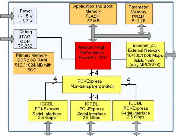
(25) Introduction. 1.5.4.. Parameter RAM (PRAM). Parameter RAM (PRAM ) holds certain pieces of information where it is useful for quick access such as variables/parameters used by the CPU and thus has a relatively smaller size. Since it is a non-volatile memory, it can be used to store information required even when power to the system is lost. The reason for not storing this information in DRAM is that it is individual (like serial number, logging data) and that it is non-volatile. 1.5.5.. Communication Interfaces. The processor has to communicate with several other units inside and outside the board: memory units, network, I/O, graphic boards etc. This communication is done through buses. Many bus technologies have emerged during the last years, with different implementations for various applications needs, but they have been unable to match the increase in performance in the CPU and memory units. In the later chapters of this thesis, further details about each component mentioned above will be given (excluding communication interfaces).. Figure 1-2: A typical CPU board for avionic applications (Source: SAAB Avitronics). 1.6. Thesis Objectives In order to evaluate and verify designs of SAAB Avitronics, it is often required to run performance tests on the computers and verify different trade-offs affecting computer performance through these tests. There has been carried out 9.
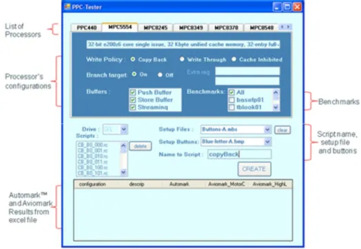
(26) Introduction. testing already in SAAB Avitronics, however such tests were limited for being onedimensional, i.e. only a portion of performance influencing parameters were tested for, mostly the cache memory (enabling/disabling and write policy in particular). The main objective of this thesis work is to provide SAAB Avitronics a multidimensional approach regarding performance evaluation of embedded microprocessors so that they can have a deep knowledge of how performance can be affected by certain parameters, enabling them to take into account while designing their future projects. Using this approach, the next objective of this project is to evaluate as many processor boards as possible from a pre-determined set of processors and see how different performance parameters can affect their performance and to compare their performances between each other as well. Another objective is to search benchmarks availables and of free use, then propose the most suitable for avionics systems and use it in the present work. After setting up a suitable evaluation procedure and fulfilling the three main objectives, the final objective of the thesis is to automate this process and make it as easy as possible for SAAB Avitronics to use for future processors when needed.. 1.7. Thesis Scope This thesis focuses on the CPU-cache memory-primary memory triangle of an overall typical avionics embedded microcomputer, thus I/O interfaces and performance of such interfaces are not considered in this thesis. Furthermore, under normal circumstances, an embedded real-time operating system (RTOS) is loaded in advance to the avionics board for initializing hardware setup prior to the execution of the application program. However, any RTOS issue is also neglected in this thesis. Finally, only performance aspects that rise from hardware are considered, thus any software issue such as compiler optimization techniques is also excluded.. 1.8. Thesis Layout Organization of the thesis is formed under five main chapters, which are as follows: Second Chapter handles the necessary theoretical background, presenting the concepts and theory behind real, practical implementations and applications. These concepts include (as in the very order presented in this thesis) superpipelined and superscalar execution, branch prediction, speculation, memory hierarchy and memory technologies. PowerPC-specific architecture implementation is presented by the end of this chapter. Instead of giving a pure theoretical point of view, we concentrate on constructing the link between these concepts and the real world applications so that the readers can understand the thesis results and conclusions much more easily and clearly. Third Chapter explains benchmarking concepts along with a list of most commonly featured benchmark programs and performance evaluation metrics used to estimate performance in embedded microcomputers. Fourth Chapter presents the methodology developed and executed during performance evaluation. A closer insight into evaluation metrics with the chosen 10.
(27) Introduction. benchmarks is shown here in more detail. Green Hills MULTI ® Integrated Development Environment (IDE) is brieafly introduced followed by illustrative examples of typical configuration scripts and setup scripts and how they are used. Fifth Chapter presents the results obtained during the execution of the tests, including comparisons between processors and configurations within each processor itself. Sixth and final Chapter is about conclusions, contributions and future work. Four appendices are added at the end of the thesis in order to give the user a deeper knowledge than presented in the thesis. This also provides the thesis to be freed from unnecessary details that could make reading complex otherwise. If readers feel that they need more information about the topics covered in this thesis, they can jump to the relevant appendix to get a deeper insight. Appendix A gives a detailed comparison of the microarchitectures of the two processors used in this thesis, the PPC440EPx from AMCC and the MPC5554 from Freescale. Appendix B gives a detailed register list of the PPC440EPx and the MPC5554 covering all important parameters from performance point of view. Appendix C provides detailed information about all the sixteen algorithms that are present in AutoBench™ benchmark and that are used in this thesis to evaluate performance of the two processors. Finally, Appendix D provides readers a manual for the graphical user interface (GUI) designed for the thesis work.. 11.
(28) Embedded Microprocessors and Memories. 2. Embedded Microprocessors and Memories 2.1. CPU The central processing unit (CPU) is the physical heart and brain of the entire computer system and it is responsible for handling all instructions and data it receives from other hardware components in the computer board and software programs running on the computer system. CPU connects to devices such as memory and I/O via data and address buses and both can be referred to as the microprocessor bus. A 32-bit microprocessor, capable of operating on up to a word of 4 bytes at a time, can have a data bus that is 128, 64, 32, 16, or 8 bits wide. The exact data bus width is implementation-specific and varies according to the intended application of the microprocessor. A narrower bus width means that it will take more time for the processor to communicate with the same quantity of data, compared to a wider bus width [25]. In practice, the bus clock speed is often slower than the CPU clock speed, which creates a bottleneck. CPU is usually the most expensive component in the hardware, so selection of the right clock speed is essential, for both its cost and the effects explained before. Thus, all possible factors affecting the performance of CPU and the overall system have to be considered. CPU also contains the L1 cache and peripheral bus controllers such as CAN, FlexRay, SPI or I 2C. It may or may not have a floating point unit (FPU), either as a part of its execution units or attached externally as a coprocessor via auxiliary processor interface (APU). Thus, their effect on overall performance should also be considered. However, in our project I/O is completely out of the thesis contents, thus we only concentrate on the FPU. Until now, software developers used to count on clock speed as a way of ensuring response times rather than investing time in finding other performanceenhancing approaches for embedded software; however nowadays the technology has started to slow down, giving glimpses that Moore’s law could be disobeyed [26] as other embedded system components such as memories, caches, peripheral devices and buses have started to make faster progress compared to microprocessors. CPU core development has recently slowed down because of a simple physical limit: power. As processors have become more deeply pipelined and increasingly superscalar over the past two decades, typical high-end microprocessor power boosted from less than a watt to over 100 watts. The CPU chip manufacturing industry is currently in the middle of a similar massive shift in the processor manufacturing field [27]. Instead of trying to get more speed out of a single processor, the multi-core architecture is becoming more and more popular where four to eight cores “divide and conquer” the load. This way, all cores can run much slower than they would alone, and by working together, the total "throughput" of the processor is increased.. 12.
(29) Embedded Microprocessors and Memories. The future of multi-core processors should be able to deliver symmetrical multiprocessing on a chip e.g. when one core is processing a calculation, another might be fetching data from memory or sending instructions to the memory [27]. Cache memory and bus architecture along with the CPU datapath is the major focus of our thesis.. 2.2. Clock Speed Every computer contains an internal clock that regulates the rate at which instructions are executed and synchronizes various components of embedded computers. It takes different number of clock cycles for the CPU to execute each instruction, depending on the processor’s instruction-set architecture (ISA). The faster the clock speed, the more instructions the CPU can execute per second, thus the more performance it has; however the digital circuitry underneath has to make transition from 0 to 1 (or vice versa) at a faster rate, increasing the power consumption of the chip and thus heat produced in the chip (mostly inside the driving transistors). The clock rate of a CPU is normally determined by the frequency of an oscillator crystal. If high performance is desired in the application, instead of reducing the clock speed in order to save power, a phase-locked loop (PLL) clock control circuit can be implemented inside the CPU chip. The PLL allows the processor to operate at high internal clock frequency derived from a low-frequency clock input; thus reducing the electromagnetic interference (EM I) generated by the system and also eliminating the need to add additional oscillators to a system. As system clock frequencies are increasing rapidly, maintaining control over clock becomes more and more challenging. In addition to generating the various clocks for the CPU, the clock generator must also provide clocks for the peripheral interfaces such as PCI, CAN, SPI or I 2C and even DMA controllers. PLL-based clock generators provide a cost effective solution for generating various frequencies that are required in today's system and meeting the demand for tighter specifications of important parameters like skew and jitter [28]. They are, however, inherently noise-sensitive and they may require expensive, highquality external components to implement a loop-filter in the PLL [29]. Subramanian et al. show that it is possible to achieve higher performance in superscalar processors by dynamically varying the operating frequency during runtime past worst case limits [30]. Their experimental results show that an average performance gain up to 57% across all benchmark applications is achievable by dynamic clock frequency tuning. Clock speed is only one measure of computer power, but it is not always directly proportional to the performance level. Clock speed is not a good measure of computing power because there are many other factors to consider when comparing the performance of microcomputers such as bus speed, clock rate of RAM, memory hierarchy, cache associativity, replacement policy, write policy and allocation policy, memory data-width, primary memory technology and size, presence of a floating point unit and so forth. The internal architecture of the CPU, the bus architecture, and the nature of the instruction set all make a difference. In some applications, the amount of random access memory (RAM) is important, too [31].. 13.
(30) Embedded Microprocessors and Memories. Furthermore, depending on the application, clock speed may not affect the overall system performance due to limitations in hardware. Even if we have a higher clock speed, we could still have poorer performance e.g. if buses are slower or memory access time is extremely high. Another factor is the clock drifts in the system. As clock speed increases compared to peripheral devices and other external components, synchronization becomes a challenge in the system. The internal architecture of a CPU has as much to do with a CPU's performance as the clock speed, so two CPUs with the same clock speed will not necessarily perform equally [32]. On the other hand, excessive clock speed can be detrimental to the operation of a computer. As the clock speed in a computer rises without upgrades in any of the other components, a point will be reached beyond which a further increase in frequency will render the processor unstable [31]. As a result of all the factors explained, clock rates should not be used alone when comparing different microcomputers or different microprocessor families. Benchmark software should be used instead since clock rates can be very misleading because of the variation of amount of work different processor chips can do in one cycle. Main factors regarding performance in addition to clock speed are explained further in later chapters of this thesis.. 2.3. Microarchitecture 2.3.1.. Superpipeline vs. Superscalar. The potential parallelism among instructions is referred to as instructionlevel parallelism (ILP) and in order to increase the performance of the CPU, we have to find ways to increase the ILP as much as possible in the processor microarchitecture. There is a wide range of techniques for extending basic pipelining concepts by increasing the ILP with two general hardware approaches to exploit potential ILP in an embedded computer: Superpipelining and Multiple Issue. Superpipelining is achieved by increasing the depth of the pipeline to overlap more instructions. However, in order to get full speed-up, the added extra pipeline stages should be balanced so that they are of same length [32]. In superpipelining, due to nature of pipelining, each stage operates at a multiple of base clock frequency. As a result, in an n-degree superpipelined processor compared to the base simplescalar processor, the new cycle time is 1/n times that of the simplescalar and operation latency becomes n minor cycles; but 1 major cycle instead of n major cycles. The issue latency, on the other hand, becomes 1/n clock cycles instead of 1[34]. The speed-up achieved using n-degree superpipelining with N number of instructions and k number of pipeline stages is [33]:. (1, ) =. (1,1) = (1, ). + +. 14. −1 ( + = −1 +. − 1) −1.
(31) Embedded Microprocessors and Memories. Here, T refers to the total execution time of each configuration, whereas S is the speed-up achieved with that configuration. The first term in parentheses shows the degree of superscalar execution (how many instructions can be executed in parallel) and the second term shows the degree of superpipelining (number of extra stages added). Thus, T (1, 1) refers to the execution time of base simplescalar processor while T (1, n) is the execution time of superpipelined processor with degree n and k stages (but only single issue) and T (m, 1) is the execution time of superscalar configuration with degree m. Obviously as N∞, Sn. Superpipelining suffers from many aspects, though. First of all, it is limited by speed of logic and frequency of unpredictable branches. In addition to this, stage time cannot productively grow shorter than inter-stage latch time; thus there is a limit for number of stages [35]. Another point is that the longer pipeline results in higher penalty for stalls and flushes. M ultiple issue, on the other hand, provides multiple pipelines operating concurrently in the datapath so that multiple instructions can be launched in each pipeline stage. Multiple issue machines are divided into two categories: static multiple issue or VLIW (Very Long Instruction Width) and dynamic multiple issue or superscalar. The VLIW architecture uses the compiler to assist with instruction issue and handling hazards (loop unrolling, instruction reordering etc.); whereas the super-scalar architecture utilizes different instruction issue policies and multi-pipeline scheduling techniques [36]. The speed-up achieved using an m-degree (or m-issue) superscalar architecture with N number of instructions and k number of pipeline stages is [33]: ( , 1) =. (1,1) = ( , 1). +. −1. +. −1. =. ( + − 1) + ( − 1). Here, as m∞, Sm. In order to achieve higher performance, the two architectures can be combined, forming a superscalar superpipeline. The speed-up of such architecture is multiplication of the individual speedups of the two architectures. In common usage, when we talk about a superscalar processor, we generally also include superpipelining, i.e. most superscalar processors also include superpipelining, forming a “superpipelined superscalar” processor or simply a superscalar processor. ILP can further be increased by using a combination of various techniques such as look-ahead execution, register renaming, branch prediction, out-oforder execution (OOOE) or speculation. These concepts are briefly explained in the following sections. 2.3.2.. Look-ahead Execution. Superscalar processors can look-ahead in the instruction stream to identify dependencies (i.e. to determine which instructions can be issued in parallel) and which instructions are ready to execute, using an instruction look-ahead window (ILW). The set of instructions considered in a certain moment forms the window of execution (WOE) which provides a full set of instructions that may be simul15.
(32) Embedded Microprocessors and Memories. taneously considered for parallel execution. Once instructions have been initiated into this window of execution, they are free to execute in parallel, and are subject only to data dependence constraints [37]. 2.3.3.. Out-of-Order-Execution (OOOE). Superpipelined superscalar processors employ out-of-order execution (OOOE) due to the fact that in-order issue pipelines stop if decoding detects a conflict. Here, out-of-order execution refers to the execution of instructions based on “data flow” rather than the actual program order. Doing so, instead of stalling, CPU can further look-ahead and work on sections of code that do not have dependencies [38]. This is done with the help of ILW. When CPU finishes decoding an instruction, it places it in the ILW. As long as the window is not full, the CPU can continue to fetch and decode new instructions. The most popular OOOE algorithm is the Tomasulo’s Algorithm, which was implemented originally for the floating-point unit (FPU) of IBM 360/91 in 1967 and it is still widely used by IBM PowerPC although it has been over 40 years since its introduction. In Tomasulo’s Algorithm, execution begins with instruction fetch. Next, in the decoding stage, fetching can continue as long as the operands are available. These first two steps are exactly similar to those in the regular in-order processor. After decoding, instructions and the operands are passed to temporary buffers called reservation stations (RS). This stage is called issue. RSs are the central data structure of the Tomasulo scheduling algorithm and they act as a queue for the instructions; they lie between the decode/issue stage and the functional units, and they provide temporary buffering before execution. Before instructions start execution in the functional units (FUs), they are stored in reservation stations and wait until all of the operands to be ready. Reservation stations are responsible from holding source registers and destination registers (and whether they are available), operation results and state of instructions (waiting or executing) [39]. They can be centralized (in this case they are called dispatch buffers) or decentralized. When results are computed, they are sent to the particular RS waiting for these specific results, and they are buffered until it is safe to put the result into register or memory. Instructions are passed to RSs even if hazards cannot be prevented in advance, which is in contrast to the in-order machine, which stalls in this case. As soon as all operands are available, the instruction is passed from RS to the FU. This stage is called dispatch and is done without obeying the program order of the instructions [40, 41]. After the FU has finished the execution, RSs can get data as soon as it is available, without the need to wait for the data to be written back to memory or registers, via a special bus called the common data bus (CDB), as long as the result is available. This stage is called completion. A simple circular FIFO buffer called the reorder buffer (ROB) keeps the original program order of the instructions after instruction issue. Data dependencies can still occur in OOOE.. 16.
Figure
![Figure 1-1: Interaction of ROM, RAM and I/O with the CPU in embedded system [9]](https://thumb-eu.123doks.com/thumbv2/5dokorg/4579030.117331/20.892.228.642.269.410/figure-interaction-rom-ram-i-o-cpu-embedded.webp)
![Figure 2-10: DRAM read and write operation [25]](https://thumb-eu.123doks.com/thumbv2/5dokorg/4579030.117331/57.892.148.747.892.1048/figure-dram-read-and-write-operation.webp)
![Figure 2-11: Four-word SDRAM burst write with DQM disable & DQM masking [25]](https://thumb-eu.123doks.com/thumbv2/5dokorg/4579030.117331/58.892.140.763.885.1076/figure-word-sdram-burst-write-dqm-disable-masking.webp)
+7
Related documents
The static nature of the application description, that is, the static input sizes and rates combined with the known kernel resource requirements and application graph, enables
Detta innebär att samma information som ges som återkoppling till eleven även tjänar som betygsdokumentation både för skolans och lärarens del.. Denna sammanblandning förekom inte
ρ d can be seen as the downlink SNR , defined as follows: If all downlink power were radiated from just one of the base station antennas, ρ d would be the average (over the
Fuzz-C™ is a stand-alone preprocessor that seamlessly integrates fuzzy logic into the C language. Now you can add fuzzy logic to your applications without expensive,
During the execution, a task need to send a group sending signal to signal handler, the signal handler would then distributed the message to the registered target.. The difference
Mousavi, Ventura and Antheaume. Decision-based territorial Life Cycle Assessment for the Management of Cement Concrete Demolition Waste. Waste Management and Research... SI
While network coding for data dissemination can increase reliability, it is harder to apply network coding for convergecast, probably the most important traffic paradigm in
The medium access protocol for the Resilient Packet Ring network is designed to ensure fairness among nodes (Gjessing and Maus 2002). The protocol offers a priority scheme with
