IN
DEGREE PROJECT MECHANICAL ENGINEERING,
SECOND CYCLE, 30 CREDITS , STOCKHOLM SWEDEN 2019
Modularization and
evaluation of vehicle’s
electrical system
NAWAR ABDO
KTH ROYAL INSTITUTE OF TECHNOLOGY
Modularization and evaluation of vehicle’s
electrical system.
Abstract
Modularization is a strategy used by many companies, to help them provide their customers with a high variety of customized products efficiently. This is done through the customization of different independent modules, which are connected by standardized interfaces that are shared throughout the entire module variety.
Scania, being one of the large companies that provide modular products, has been successfully improving their modularization concepts for many years, and is one of the most iconic companies when it comes to modularization of buses, trucks and engines. But with the increasing need of electronics integrated in the vehicles, it is becoming more and more important to modularize the electrical system.
There is currently an existing, modularized, product architecture for the electrical system, and Scania wants to know how well modularized it is, as there is no unified way that indicates what is
considered to be the better solution.
To analyze the current state of the electrical system, a systematic method of modularization was used, which would help answer three important questions: Are the modules well defined? Is there a way to systematically compare alternative solutions? What criteria are more important to focus on? Since there is no unified way of modularization, many modularization methods have been created, and each one has been optimized for a certain purpose.
This project compares three different modularization methods and then uses one of the methods which is deemed to be the preferred method to help provide the answers that the company seeks when investigating the modularity of the electrical system.
As the electrical system is very complex, and the project has limited amount of resources, it was decided to choose one of the control units as an example, which was the APS (air processing system). The literature study showed that the most rewarding method to use was the MFD (Module Function Deployment), as it provides more information about the product and what criteria the company should focus on. It was then decided to use the relevant steps in MFD to analyze the state of the APS as an example of how this method works.
Keywords: Modularization, modularity, module, evaluation, comparison, module function
Sammanfattning
Modularisering är en strategi som används av många företag, för att hjälpa dem att erbjuda sina kunder en mängd olika anpassade produkter på ett effektivt sätt. Detta görs genom anpassning av olika oberoende moduler, som är kopplade med standardiserade gränssnitt som utnyttjas av alla modulvarianterna.
Scania, som är ett av de stora företagen som erbjuder modulariserade produkter, har framgångsrikt förbättrat sina modulariseringskoncept under många år och är ett av de mest ikoniska företagen när det gäller modularisering av bussar, lastbilar och motorer. Men med det ökande behovet av
elektronik integrerad i fordonen blir det allt viktigare att modularisera det elektriska systemet. Det finns för närvarande en befintlig, modulär produktarkitektur för det elektriska systemet, och Scania vill veta hur väl modulariserat det är, eftersom det inte finns något enat sätt som anger vad som anses vara den bättre lösningen.
För att analysera det elektriska systemets nuvarande tillstånd, måste en systematisk metod för modularisering användas, vilket skulle hjälpa till att svara på tre viktiga frågor: Är modulerna väldefinierade? Finns det ett sätt att systematiskt jämföra alternativa lösningar? Vilka kriterier är viktigare att fokusera på?
Eftersom det inte finns något enhetligt sätt att modularisera har många modulariseringsmetoder skapats, och var och en har optimerats för ett visst ändamål.
I projektet jämförs tre olika modulariseringsmetoder och använder sedan en av de metoder som anses vara den föredragna metoden för att hjälpa till att ge svaren som företaget söker när man undersöker modulariteten hos det elektriska systemet.
Eftersom det elektriska systemet är väldigt komplext och projektet har begränsat antal resurser beslutades det att välja en av kontrollenheterna som ett exempel, vilket var APS
(luftbehandlingssystem).
Litteraturstudien visade att den mest givande metoden att använda var MFD (Module Function Deployment), eftersom det ger mer information om produkten och vilka kriterier företaget ska fokusera på. Det bestämdes sedan att använda de relevanta stegen i MFD för att analysera APS-tillståndet som ett exempel på hur den här metoden fungerar.
Nyckelord: Modularisering, modularitet, modul, evaluering, jämförelse, module function
Nomenclature
MFD: Module Function Deployment. QFD: Quality Function Deployment. PDM: Product Design Matrix. MIM: Module Indication Matrix. FSH: Function Structure Heuristics. DSM: Design Structure Matrix. APS: Air Processing System. ECU: Electrical Control Unit.
MCPV: Multi-Circuit Protection Valve. AD: Air Drier.
DFA: Design for Assembly. DFService: Design for Service.
Acknowledgement
This project was conducted with cooperation with KTH Royal Institute of Technology in Stockholm, and Scania in Södertälje.
I want to thank my supervisor at KTH, Gunilla Sivard, for guiding me and helping me stay on track throughout the whole project. I also want to thank my supervisor at Scania, Johan Svahn, for providing me with feedback and information needed to facilitate my work.
A special thank you to Colin de Kwant, who also helped with defining the scope and delimitations of the project, and helped me get in contact with consultants at Modular Management. Also, thank you to all the participants in the interviews that contributed with insightful information needed in this project.
Table of Contents
1. Introduction ... 1 1.1. Background ... 1 1.2. Problem definition ... 1 1.3. Goal ... 1 1.4. Method ... 2 1.5. Delimitation ... 2 1.6. Expected result ... 22. Literature study and interviews ... 3
2.1. Module ... 3
2.2. Modularity ... 3
2.3. Modularization ... 3
2.4. Modularization methods ... 4
2.4.1. Function Structure Heuristic method (FSH) ... 4
2.4.2. Design Structure Matrix (DSM) ... 4
2.4.3. Modular Function Deployment (MFD) ... 5
2.5. Interviews ... 11
3. Analysis ... 12
3.1. Analyzing modularization methods ... 12
3.2. Analyzing interviews ... 15 3.3. Investigation of APS ... 17 4. Result ... 23 5. Conclusion ... 26 5.1. Recommendation ... 26 5.2. Future work ... 26 6. Sources ... 27 7. Figures ... 29 8. Appendix ... 30
8.1. Standard questionnaire for Module Indication Matrix (MIM) ... 30
8.2. Altered questionnaire for Module Indication Matrix (MIM) ... 31
8.3. Interviews ... 32
8.3.1. Interview 1 – Karl Bråtegren, Senior Manager at Modular Management. ... 32
8.3.2. Interview 2 – Frank Rood, Senior Consultant at Modular Management. ... 34
8.3.4. Interview 4 – Jacob Johnsson, Senior System Owner at Scania. ... 38 8.3.5. Interview 5 – Thomas Strange, Head of Systems Hardware Architecture at Scania. .... 41
1
1. Introduction
1.1. Background
Scania is well-known for the modularization of their trucks, buses and engines.
Modularization aims at providing the highest possible customer variability in the products with minimal number of items, given defined customer applications.
The modularization concept, to standardized interfaces between components, which can be varied in different performance steps for different customer requirements, as long as the standard interface is retained, is used in the mechanical design process. But with more electronics introduced in vehicles, the need to effectively modularize the electrical system is increased more and more.
However, electrically realized features have more interfaces that can be modularized. Possible dimensions, other than electrical components, are functions, logic, and software. There is ongoing research in nearby subjects in Scania, but relatively little is systematized around electrical systems.
1.2. Problem definition
The electrical system continuously grows through several upgrades and improvements. Therefore, the company wants to create a well-modularized electrical system, to facilitate the upgrade process and avoid unnecessary re-work. The company does several
investigations before making important decisions regarding the architecture of the electrical system. Changing or revising the architecture can be very costly, in both development resources and implementing a new variant in the product range.
The project is about how to analyze and investigate the modularity of the current electrical system used in the company's vehicles. Through the survey, a methodology will be provided to evaluate the modules in the electrical system. In addition, the project will define which interfaces are most important to standardize in order to achieve a good modularity.
1.3. Goal
The aim of the project is to contribute to an understanding of the assessment and
evaluation methods of modules. The evaluation should take into consideration the size of modules in relation to the functions, and the modules' interdependencies.
The size of module will be examined to see if there are functions that overlap on multiple modules, or if one module has too many functions and should be split up.
In addition, the importance and weight of modules must be examined to give the company an alternative point of view on which modules and interfaces should be standardized. The questions that are going to be investigated and answered are:
- Are the modules well defined? Do they have proper size relative to their functions? Should the module be broken down into smaller modules or should multiple modules be integrated into one module?
- How to evaluate and compare multiple solutions? Is there a way to compare solution A and solution B? And what effect they might cause?
- What criteria are more important to focus on? How should the resources be split among the projects to reach best result?
2
1.4. Method
In order to achieve the goal, an examination of different modularization methods was done, to give an understanding of how the different methods identify and divide the modules. After that, the relevant method was used to analyze and evaluate the various modules. Interviews at Modular Management Group in Stockholm were conducted, as they have developed one of the methods that this project will be comparing. This successfully provided an in-depth perspective on how to consider evaluating complex systems, where both software and hardware are connected.
The examination of the importance and weight of modules was based on the company's estimation of the criteria used in the development of the electrical system. By setting up module drivers against the technical solutions that the company has developed, and rating them according to the company's values, the importance and weight of the modules was determined.
1.5. Delimitation
The project did not analyze all control systems and modules in the electrical system, but only one control system was chosen as an example to perform the work. Later on, the method that was provided in this project can be used on the remaining control systems and modules.
1.6. Expected result
The expected result was to provide a study that will help Scania to evaluate the modular system for electrical control systems. The study should also contribute to an alternative way of thinking when selecting modules and their interfaces.
3
2. Literature study and interviews
2.1. Module
The term module is used in many different fields, such as music, mathematics, programming and even engineering. And it can look different depending on which field it is used in. Looking at the engineering definition, a module is a unit that consist of strongly connected structural elements in within, and weakly connected to other elements or units.
With other words, modules are independent units within a larger system that work together to allow the whole system to function as intended. The system provides the framework to allow the independency of the module structure and integration of the module functions. This is also known as the “system architecture”. (Baldwin, 1999)
2.2. Modularity
Modularity is a concept that aims to deal with complex systems, and it consists of two general ideas.
The first idea is to have the elements reliant on each other within the module, but also
independent across other modules.
The second idea consists of concepts:
- Abstraction - Information hiding - Interface
The purpose of this idea is to help manage complex systems or even solve complex
problems. This is done by breaking it up in smaller pieces and look at each piece separately. In the breaking process, it is important to look for “points of natural division”, which are points where the system is easily divided while still fulfilling the criteria of the modules. After the breaking process, it is possible to isolate and hide the complexity of the elements behind a separate abstraction with a simple interface.
It is best to start this process when the complexity of the system, or problem, threatens to slow down or prevent the progress toward the goal. (Baldwin, 1999)
2.3. Modularization
Modularization is a strategy used in various areas to provide the customers a large selection of products and the ability to customize those products with as few module variants as possible. As Schilling mentions, that it is possible to see almost all entities as “hierarchically nested systems”, which means the entity is a system of components. (Schilling, 1999) The purpose of modularization is to increase efficiency by reducing complexity. Rather than focusing on creating an optimal design for the optimal product, modularization aims to create a strategic and flexible product design, to allow multiple product variants to be obtained without the need of changes to the entire product as a whole. This approach suggests to build the best product variants, with respect to the whole product life cycle. (Ericsson & Erixon, 1999)
4
Succeeding in creating an efficient modular system can provide a company many benefits and advantages, one being the opportunity to efficiently customize their products. Other advantages can be the ability to update or upgrade each individual module separately without the need to make large changes to the entire system as a whole. This in turn can help the company to save money and offer their customers better prices on their product series. Furthermore, the company is able to focus on being competitive on both fronts, economic and technological, instead of having to sacrifice one of them. (Kuemmerle, 2017)
2.4. Modularization methods
2.4.1. Function Structure Heuristic method (FSH)
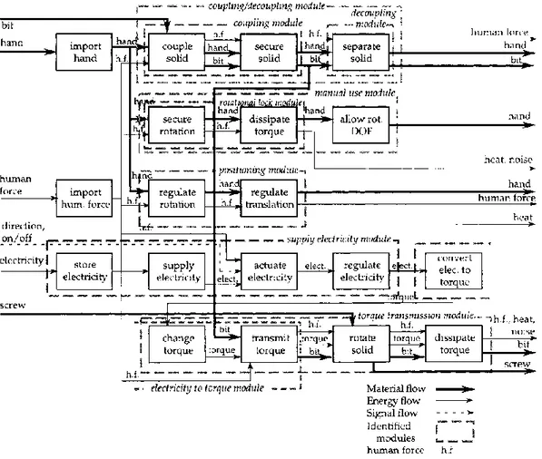
FSH is defined as an examination method that helps a designer to identify modules in a design problem, by using empirical methodology and rules of thumb.
In this method, the product’s functions are broken down in a block diagram, including the flow of information, material and energy between those functions. It separates the modules from a specific product’s function structure, by identifying the dominant flow, branching flows and conversion-transmission function pairs.
FSH starts with function structure, then compares the different module alternatives and solutions, that are defined by a group of functions according to the heuristics. Through this, possible solutions and modules are defined, and the most appropriate solution or module is chosen.
The most important criteria of this method is the functionality of the product, and the module interfaces. (Stone, 1998)
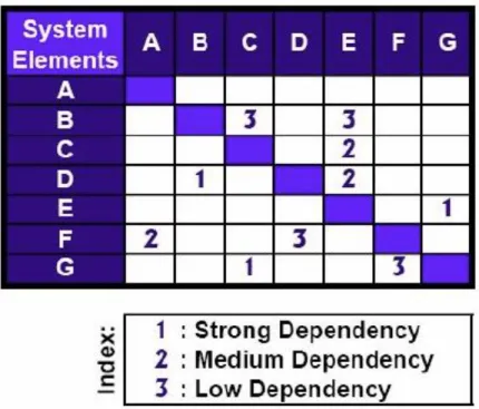
2.4.2. Design Structure Matrix (DSM)
DSM is used to organize the product development tasks and teams, to avoid any unnecessary re-work, which in turn helps to manage and speed up that development. DSM is furthermore used to define modules in a specific product architecture. In an architecture DSM, the components or functions are positioned in a row and a column, to then be mapped against each other. The mapping is done to visualize the interactions between these components/functions. It is symbolized by a grade or a number, “coupling coefficients”, depending on how strong the relation is between them, and whether it’s a positive or negative relation.
After these functions/components, and their relations are placed in the DSM, procedures can be applied to group them, taking into consideration to maximize the interaction within the groups and minimize it between groups, (Holtta, 2003). As one of these procedures, the DSM can be “partitioned”, to create a clear structure that allows easier and better planning, (Yassine, 2004).
The groups that are formed as a result of the partitioning can be seen as possible modules. The idea of the procedure is to rearrange the columns and rows to make the groups tighter. This can also cause overlapping in modules, which, in turn, is the responsibility of the designer how to deal with them.
5
DSM is designed for complex product architectures, and it focuses on the interfaces of the modules, which makes the design process easier. (Holtta, 2003)
2.4.3. Modular Function Deployment (MFD)
“Another modularization method, perhaps more management- and less engineering-oriented, is MFD. It is also based on functional decomposition, but in this method, modularity drivers other than functionality are considered. MFD is designed to modularize a single product. There are twelve modularity drivers in MFD. The first is carryover i.e. a specific function will carry over to different products and no technology changes are expected. The next two, technology evolution and planned product changes, take both unexpected and expected changes into account. Different
specification enables product variation and styling considers how the modularity choice would affect the appearance of the product.” (Holtta, 2003)
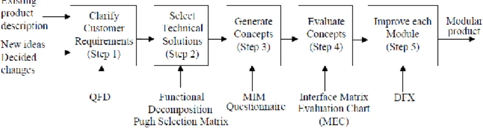
This method consists of five major steps. It starts with a Quality Function Deployment (QFD) analysis to clarify customer requirements and to identify important design requirements with special emphasis on modularity. The functional requirements on the products are analyzed and technical solutions are selected. After that, a systematic generation and a selection of modular concept is done, where the Module Indication Matrix (MIM) is used to identify possible modules by examining the interrelation between module drivers and technical solution. This will also allow you to integrate multiple functions into one single module. The result of each modular concept is then evaluated, depending on what the company wants and needs. (Erixon, 1998)
Figure 2.4.3 - 1 Modular Function Deployment, MFD
The steps that MFD consists of are: - Clarifying Customer Requirements
In this step, the company needs to make sure that the design requirements are derived from customers’ needs. Clarifying customer requirements, means that the product specifications are clearly formulated. It is appropriate to use QFD in this step, as it can ensure that the correct data is attained from the customers.
6
Figure 2.4.3 - 2 Quality Function Deployment, QFD
QFD will help the company to understand what their customers wants, and to what degree they want it. It indicates what the customer prioritizes. This also helps the company to position itself in the market in relation to their
competitors, and offer their customer a more suitable solution. This is done, for example, by choosing the right pricing for their products according to what the customers are asking for.
- Selecting Technical Solutions
The data attained from the QFD performed in the previous step will be fairly customer focused, and therefore, it will need a technical interpretation in order to continue. This is achieved by viewing the product from the function perspective. The company needs to identify the functions and sub functions that will fulfil the customer needs, and select the equivalent technical solution. This is a very important step, as it will provide a mutual
understanding of the product and how every part contributes to the whole system.
The prime condition for achieving good modular design is the independency between the different functions and technical solutions. Therefore, it is good
Pricing
High
Low
Low High Quality
7
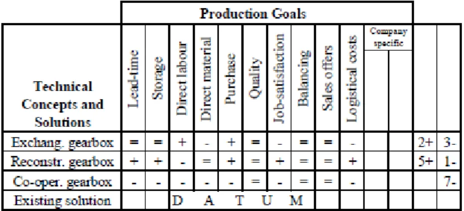
to use a structured method to perform a functional decomposition. An example for this method is Product Design Matrix (PDM).
Figure 2.4.3 - 4 Product Design Matrix, PDM
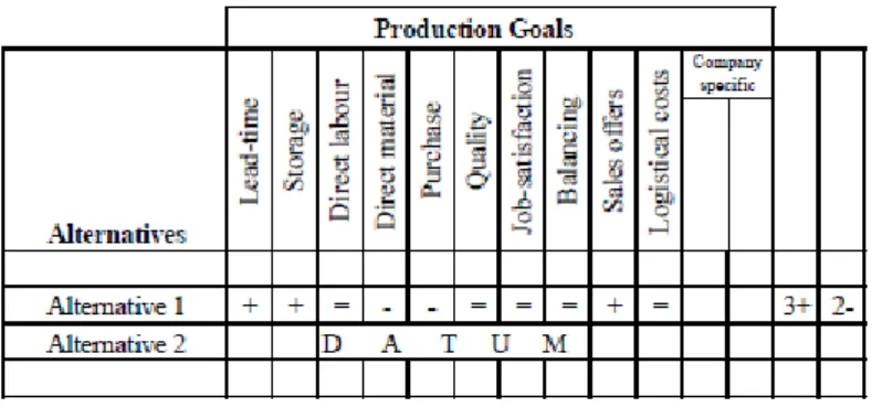
During this process, multiple solutions to different functions might appear, and the company will have to select the most appropriate solution. An evaluation can be conducted to see the value in the different solutions, compared to the current one.
Figure 2.4.3 - 5 Example for evaluating alternative solutions with Pugh matrix.
- Generating Concepts
Here, the technical solutions from previous step will be analyzed based on a number of different driving forces. These criteria are called “module drivers”.
Development Carry-over
Technology push
Planned design changes
Variance
8 Styling Production Common unit Process/organization Quality Separate testing Purchasing
Supplier offers black box
After sales
Service and maintenance
Upgrading
Recycling
These are the standard drivers, but the company could change them or complement them, depending on their needs.
These module drivers are used as the basis of a systematic evaluation of the sub-functions within a product. For that reason, a matrix was formed, where every sub-function could be mapped and evaluated against the module drivers. This evaluation can only be done after the sub-functions have been properly translated into technical solution, reasonably detailed, providing a basis for the needed considerations.
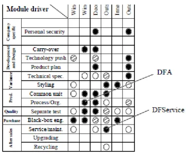
The formed matrix is called Modular Indication Matrix, MIM for short, and it is considered the heart of MFD. It has some similarity to QFD’s approach, where it gives an indication of what sub-functions could be grouped to form a module. All the modules are graded according to how important it is for it to be a module. 9 = strong driver, 3 = medium driver, 1 = some driver.
9
Figure 2.4.3 - 6 Module Indication Matrix (MIM)
To help grade the modules and module drivers, a questionnaire is provided in the appendix. (See Appendix 8.1.)
Many or unique module drivers that are highly graded, indicates that the module in question has a complex requirement design, and is more likely to form a module on its own. A unique module driver design could indicate that a module should be kept single as long as possible.
Few or low graded module drivers, indicates that the module could be easy to integrate, or even grouped with other modules. Provided that they match each other’s module drivers, without any contradictions.
Example of the contradicting module drivers can be seen in 3.1. Investigation of APS.
To evaluate any changes, another Pugh matrix can be used, to compare different concepts.
10 - Evaluating Concepts
After comparing the multiple modular concepts, it is time to do a selection, and further evaluate those alternatives. This is to give a better understanding on what effects are to be expected from those changes, and whether they are better or worse than the current concept.
Although a comparison is done in the previous step in the form of a Pugh matrix, it is important to do further evaluation and measure the effect resulted from these changes.
“For a modular design, the interfaces between modules have a vital influence on the final product and the flexibility within the assortment. Thus, firstly, an evaluation of interface connections will be the important factor for the selection of the concept.” (Erixon, 1998)
There are different types of interfaces, such as:
Fixed: where the interfaces only connect the modules and transmit force. Moving: where the interfaces transmit energy in form of rotation.
Media: where the interfaces transmit fluid, electricity, etc.
In addition to interface evaluation, it is important to consider the economical effect of these changes, if it is even possible. Whether the changes will be economically profitable.
- Improving Modules
This is the step, where the modules are visualized and improved. Each module is investigated separately to decide the design strategy of it.
The MIM works as an indicator for what’s important for the modules.
Example, if a module is mostly focused on serviceability, it should be designed to ease disassembly. Modules that are created by different teams, or bought from suppliers, should be designed for assembly, also known as DFA. (Erixon, 1998)
11
2.5. Interviews
In order to gain a better understanding of how modularization is done in electrical systems and other logic products, interviews were conducted in both Scania and Modular
Management.
The purpose of these interviews, is to provide a clear picture of how the modularization method used to develop the electrical system is structured, and how other companies do to solve similar problems. It is also important to know how these companies choose and evaluate their modules, and what module drivers they find most relevant.
The aim of this is to make a comparison between the different methods, mindset, and evaluation processes that these companies use.
The participants that partook in the interviews were:
Karl Bråtegren, Senior Manager at Modular Management. (Appendix 8.3.1) Frank Rood, Senior Consultant at Modular Management. (Appendix 8.3.2) Erik Dyrelius, Senior Engineer at Scania. (Appendix 8.3.3)
Jacob Johnsson, Senior System Owner at Scania. (Appendix 8.3.4)
12
3. Analysis
3.1. Analyzing modularization methods
To reach the goal of this project, the question stated there will be answered by using a modularization method. This is to map the current state and visualize the situation, and methodically evaluate modules.
In this project, three modularization methods has been investigated, to decide which one is most appropriate to answer the questions, and help the company improve their modules in the future. The methods are:
- Function Structure Heuristics (FSH) - Design Structure Matrix (DSM) - Modular Function Deployment (MFD)
FSH is a viable option to evaluate different alternatives of modules and solutions, as it is a
straight forward approach and quickly breaks down the product into its sub-functions/parts. This provides a rough picture of the whole product, and helps to understand how all the parts interact with each other. Thereafter, it is possible to consider all the possible
alternatives of modules and other solutions, which would help the product improve in the best way.
It is of course decided by the individuals that are working on this product, or designer, to decide which alternative is most appropriate/profitable, as this method requires a lot of experience and for the designer to be very knowledgeable about the product.
Theoretically this methods sound very good, and a worthy contestant for the method that will help reach the goal of this project.
The issue remains that it only provides a rough picture of the product, and does not give any details on what interfaces are more important to focus on. The more complex the product is, the more complex the mapping will become using this method.
13
Figure 3.1 - 1 Example of Function Structure Heuristics
The pros with this method is that it’s simple to implement, and is not very time consuming, especially for simple products.
The cons are that it does not provide enough information compared to other methods, and it can become very complicated if used on complex systems/products.
DSM is a helpful method to identify the dependency and interaction between
functions/parts, by mapping them against each other. This method will provide a picture of how these functions/parts interact with each other, which will help to identify whether some functions should be integrated/grouped together, or even broken down into smaller sub-functions. This is decided by the grade of interconnectivity that is given, or how strong the interaction between those functions are.
By identifying what interactions have higher priority, it also identifies what interfaces the company should focus on standardizing. This is decided by the designer, who could use his experience and what criteria the company value most to reach the best solution.
This method could be used to answer one of the questions stated in the goal section, which is how well the modules are defined.
Compared to FSH, this method works well with complex systems, as the matrix system is a lot more structured and easy to read. It provides the needed information, without the need to draw large and complex maps of how everything is connected.
14
Figure 3.1 - 2 Example of DSM with dependency grades
As seen in the figure above, it grades the dependency between multiple elements. The pros with this method is that it will help define modules, by identifying dependencies between functions/parts, and try to group those functions together. This also leads to identifying important interfaces.
Cons are that this method does not have any way to systematically evaluate different solutions, whether choices are profitable or not, it does not provide any information about what criteria are important, or what the reason for changes are. It does not answer all the questions in the goal section either.
MFD is a method for module management, which focuses on evaluating all the action taken
from customer needs to finished product. Every step in this method focuses on identifying and evaluating actions and changes. For example, the QFD will help identify the customer needs and how it will be fulfilled, then grade them how well those solutions fulfill customer needs.
Since this method could be seen as a systematic evaluation process, it also help new employees to understand the situation faster, and most of the information is displayed through matrixes. Compared to other methods, where the designer would have to
brainstorm ideas and estimate the effects they would cause, the standardized process will help evaluate every step taken.
As this method covers significantly more areas than the other two, it is apparent that it will provide more information and paint a clearer picture of the whole situation. But since there was not enough time to go through the whole method, the project only covers step 2 and 3 of this method. These steps uses three matrixes, PDM, Pugh and MIM, which are capable of answering the questions in the goal sections.
PDM will focus on evaluating how well defined the modules are, as mentioned in the literature section, functions should be isolated to one modules, instead of overlapping on
15
multiple modules. This method will identify new modules, whether more functions should be grouped together, or if a module is large and should be broken down into smaller sub-functions.
If there are multiple solutions to the PDM, a Pugh matrix could be used to evaluate those alternatives, and to see what effect they can cause. This is an excellent way to compare evaluate multiple solutions and modules.
The MIM will help identify what criteria the company values most, which in turn helps to allocate resources more efficiently. By taking the standard criteria, or “module drivers” as they are called in this method, the company will be able to grade and evaluate module drivers, so that more time can be spent on the important modules that are highly graded, or has more profitability in implementing.
This method is huge, and has multiple steps, but it still is simple as it guides the designer through those steps. It could be easier to be understood by new employees, rather than needing experienced designers, that have been working on the product for years, to implement any new changes.
The pros with this method is that it is an excellent way to evaluate and identify solutions and modules. It provides a clear picture of what modules should be integrated or separated, and how resources should be spent. Every step is well documented, with great detail and easy to understand. This method also manages to answer all the questions in the goal section.
The cons are that this method is, if fully implemented and used, is time consuming the first time, as it has to map the whole situation from customer interaction to final product. Hence the decision of only using two steps out of five for this project.
3.2. Analyzing interviews
Comparison of modularization methods:
From what is learned from the interviews at Scania (see: 8.3 Appendix), there are no systematic methods of modularization regarding the electrical system. Instead, they work with pre-development and pre-study of the module system, and use experience from their previous project in the new ones.
This is not necessarily good nor bad, as it assures experienced people, which have been working with this system for a long time, to continue working on it and improving it. The knowledge from previous project is used efficiently, to identify problems and reach a solution.
But this could also cause problems for new employees to provide assistance in improving the system, as there is no documented method, but they will have to first study: the whole system, and how the modules communicate within it; how the projects usually work and how they aim to solve problems and what criteria they focus on while they solve those problems. All this information could take time to learn and understand, in order to get the new employees up to speed. Another problem could be that people who will go into retirement will leave the company with their knowledge, which is a huge loss to the company.
16
A systematic method to modularize the system would greatly increase efficiency. Especially when it is easy for new employees to join the team and see a visualized map of the current state of the system, and how the group works.
In comparison to Modular Management, where the MFD method is used, it makes it easier for consultants to analyze the current state by using the systematic steps, and help the companies improve their modularization processes.
Although, when working on an already existing module system, the method of MFD is slightly changed, as to define the existing modules. This is done by including external methods, which could be as simple as drawing the modules on a whiteboard, to see how they are all connected. It could also be a more in-depth pre-study, if the situation calls for it.
Comparison of module drivers/criteria:
Comparing the choice of module drivers/criteria of both companies, it is clear that Scania’s criteria are more business related. As Erik mentioned, the cost of having different systems and the number of variants available, which correlate with the maintenance of those variants.
Another criteria that Erik mentioned was flexibility, for example flexibility in size, which also helps to scale down on different variants. “Need’s fulfillment” was also a criteria, which reflects the work of Scania to best meet customer demands. On the other hand, the standard module drivers used in MFD and by Modular Management are mostly product related. Although, product related module drivers change from company to company, and from one product to another (hardware compared to software), the analysis of them provide a better understanding of the product. , This will lead to less time wasted on less important aspects of the product, making it easier for workers to do their job. Further, the clarification of modules and their interfaces helps the company to assign the right people to the right job, which in turn provides better results.
Comparison of weighing process:
At Scania, there does not seem to be any unified method to weigh the importance of
module drivers/criteria of the modules. According to Jacob there is no weighing process, but there is an ideology of “same problem – same solution”. Thomas, on the other hand,
mentions that all the criteria are equally valuable in the beginning, but there will be some balancing throughout the project, depending on the benefits.
It is understandable that there are different ways of working, and different understanding of the weighing processes, in a large company as Scania. Each of those departments might have their own way of working, which fits them better, but it raises a question as whether it would be better to have a unified process and way of thinking.
Modular Management, on the other hand, uses MIM as a weighing process, as intended in MFD. According to Frank, they align with the customer which drivers make sense to their specific situation, and add them into the MIM as additional drivers. This also gives them a better understanding to which module has “stronger reason” to implement, according to Karl.
17
This unified understanding of the process could be seen as positive, as a consultant from one project could start working on other project without having huge problems, since they will already know the process of work. At least the processes would be very similar.
3.3. Investigation of APS
Module examination through PDM.
To get a better understanding of the module system, a closer investigation of the control units must be done. This will assist in analyzing the current state of the module system. In this example, the air processing system will be studied. The functions of this system will be identified and mapped against their respective technical solutions.
The purpose of this system is to dry the air in the compressed air system and to control the compressor.
After studying the schematics of the system, it was possible to create a matrix mapping the functions against the technical solutions. This matrix will show the complexity of each module and how many functions are imbedded in each module.
Technical Solution P ressur e sens o r Te m p erature se n so r ECU MCP V AD Function Pressure signal X Temperature signal X Signal manager X Prevent overpressure X Prevent pressure failure X Circuits manager X Dry air X Filter air X
Figure 3.1 - 3 Product Design Matrix for the current state of the APS
Analyzing this matrix shows that the modules in this example are very well isolated, as the functions does not carry over to other modules which would cause unnecessary
complications in the system. Still, another question surfaces as some modules has visibly more functions than others: is the MCPV module to big and should it be broken down in smaller modules?
Considering the functions related to MCPV, it is understandable that the functions are integrated in the same module. A unit that separate and manages the air pressure circuits, and at the same time also has fail-safe measures and functions related to the air pressure, is a good decision, so that incase anything wrong happens to the air pressure, it will be
18
resolved within the module. Moreover, splitting the module in more parts would mean that pneumatic connections would have to be spread out, rather than having them connected to one module. That would also cause unnecessary complications in the system.
Unfortunately there were no available documents to compare different solution
alternatives, as it is recommended when using this method and having multiple solutions. But it is helpful for the company to consider it, when using this method of evaluation. Providing the company with an example and enough information to how it is used would be sufficient.
Module evaluation through MIM.
MIM is a one of the MFD tools that is used to identify modules, by examining the
interrelationship between criteria/module drivers and the technical solutions. This is done by mapping both module drivers and technical solutions, and rating them according to the interrelationship between them. At the end, a total number will be provided that will
indicate whether there is any opportunity for integration between modules. The total on the bottom indicates the weight of each technical solution, this is to give an idea of how the company should divide resources, and focus on what is more relevant/important.
MIM can also be used to visualize the weight of each module driver, and the quality of each technical solution.
In this MIM, the standard module drivers are used except for one, which is “styling” that is replaced by “independency”.
The module drivers used to evaluate the APS are:
Carryover means a part of a product can be reused in a newer version of the product.
This will separate a quick fix to a problem from a solution that will continuously be used in the future.
An example of this was brought up by Thomas Strange in an interview, where a problem they face is that when designers are very focused on solving a specific problem they might miss or not consider the full picture. This could result in a quick fix to their problem that they might not be able to use in the future.
Technological evolution refers to a part that is likely to go through a technology shift
throughout its life cycle. This can be a result of expected and radically changing customer demands. Either the technology changes, or there might be newer material that could be used instead of the current one.
Planned design changes refers to when a part is still in development or that the company
intend on continuing to develop.
Technical specification refers to a part that carries the product’s variance and performance
properties. To handle product variation and customization effectively, a designer should strive to allocate all variations to as few product parts as possible.
Independency refers to the ability of parts that can work independently without the need of
an additional external parts. This is to avoid any “incorrect” signals or malfunctioning parts affecting it. Having this part working without any dependencies provides lower risk for failure.
19
A Common unit part can be used for the entire product assortment or large parts of it. Such parts often carry functions required by all customers. This should be carefully differentiated from a carry over, which is shared from one generation to the next.
Process/organization refers a part that have a common internal process and could be
clustered together. Such parts can be clustered based on suitable work content, special process skills, manageable ergonomics, and long lead-time.
Separate testing refers to parts that have particular requirements in internal quality control
can be clustered together with the separate testing driver. This is mainly due to the reduced feedback times. The complaints and quality loss statistics may be searched if part quality is a concern.
Strategic supplier parts are those suitable for purchase from vendors as standard modules,
instead of buying individual parts from subcontractors. Sometimes known as black-box engineering. This approach implies that a supplier takes total responsibility for
manufacturing, development and quality.
Serviceability brings together the parts where quick service and maintenance in the field is
an important customer requirement. Clustered parts can form a service module. With properly designed interfaces, a new module can quickly replace a damaged one.
The Upgrading driver brings together the parts that will require upgrading after sales. This approach offers customers the possibility of changing the product in the future. This change is often related to an introduction of new features or performance improvement.
Recycling brings together the parts that have the same recycling process. This driver is
suitable for products with high emphasis on sustainable design, either for regulatory or marketing purposes. Environmentally hostile or easily recyclable material can be kept separate in specific modules so that the disassembly of the product will be simplified.
20 Technical Solutions P ressur e sens o r Te m p erature se n so r Elect ro n ic C o n tr o l Un it M u lti -Cir cui t P ro te ctio n Val ve Ai r D ry er :T o ta l M o d u le dri ver s Carryover 9 9 3 21 Technology evolution 9 9 18 Planned design changes 0 Technical specification 9 9 Independency 9 9 9 27 Common unit 9 9 9 9 36 Process/organization 9 9 9 9 9 45 Separate testability 9 9 1 19 Supplier availability 9 9 9 9 9 45 Service/maintenance 9 9 3 3 9 33 Upgrading 0 Recycling 9 9 9 9 9 45 Total: 63 63 57 57 58 Figure 3.1 - 4 Module Indication Matrix with rough estimations
9 = Strong driver, 3 = Medium driver, 1 = Weak driver
There are two important things to keep in mind here. First is that some module drivers are contradictory to each other, which means it wouldn’t be wise to put a high grade on those module drivers for the same module. The module drivers that could cause conflicts with each other are:
- Carry over <-> Technology evolution - Carry over <-> Planned development - Common Unit <-> Technical specification
The second thing is that the questionnaire was aimed to help map the current situation, and not to evaluate future plans. That part is for the company to decide, and it would take more time than the project could manage.
The MIM above shows a rough estimation of the modules that was conducted with help of Johan Svahn, as it is difficult to estimate all the modules without having all the groups involved in the same room.
The analysis of the APS with the grading of each module driver is as follows:
21
The sensors, both pressure and temperature, have high grade, as they are likely to be used in next generation of the product as is, without any changes.
The air dryer has a medium grade as it is not entirely carry to the next generation, but some changes might occur caused by technology push.
Technology evolution:
The reason why the ECU and MCPV are not considered a carryover is that most changes that will occur, will be in those two modules.
Planned design changes:
None of these modules are still in the development phase, hence none of them are connected to this module driver.
Technical specification:
While grading the modules, the only technical specification was MCPV which had a grade of 9. But since it was graded high on common unit as well, it would cause confusion and conflicts, so this issue had to be revisited. After some further consideration, it was decided that the MCPV was a technical specification as there are more than one variant, which does not allow it to be a common unit.
Independency:
Most of the modules in the APS seems to be independent, except for the MCPV where it has some slight dependencies. This could be a result of being a variant, it depend on the air pressure needed/provided for it to work properly.
Common unit:
As mentioned earlier, the MCPV was not eligible to be a common unit, as it was considered a technical specification. Other than that, the other modules are considered as common units, and are used in multiple products.
Process/organization:
It was mentioned that, since all the modules have their own “product owner” and worked on separately by different groups. Hence the high rating on this module driver.
Separate testing:
The sensors are bought directly from the supplier, pre-tested and should be ready to work. Therefore, it was decided not to grade the sensors on this module driver. The ECU and MCPV are important to have tested separately, to make sure they work before assembling them. And the air dryer might be tested in some cases, hence the low grade.
Strategic supplier:
All the modules are bought from the supplier pre-built as a “black box”, thus the high grade for the modules.
22
Some of the modules are easier to service and replace than others, in case they break or malfunction. The sensors and air dryer have a high grade as they can easily be replaced, but the ECU and MCPV will need more work.
Upgrading:
Currently it is not possible to upgrade the modules that are in the vehicle that the customer buys. What could get upgraded is the software, which is not included here.
Recycling:
All the modules should be recyclable, as there are many rules and laws for how much of a product that should be recyclable. Hence the high grade for all modules.
23
4. Result
The analysis has now provided information through:
1. Comparison of different modularization methods, to properly understand how they can be used to assist with the goal of the project, and which method could be used most efficiently. 2. Comparison of the interviews that were conducted at both Scania and Modular
Management, which helps to understand the work process when it comes to modularization. One important point to note, is that at Scania the work process differ from one group to another, compared to Modular Management where it is fairly similar.
3. Investigating one of the control units, the Air Process System, to try and use the chosen modularization method to analyze the current state of modules, and the way the company weigh important criteria.
The comparison of modularization methods lists the pros and cons of each method, and how they can assist in this project. The most viable option and the one that can help, both this project and the company in the future, is MFD.
Other than the ability of answering the questions of the project through systematic steps, it is also a very good method to manage information about the product, its modules and what criteria are important for the company to focus on. For that reason, it was chosen as the method to use in the investigation of the APS.
After the selection of method to be used in the investigation, interviews were conducted at both Scania and Modular Management.
The interviews at Modular Management, provided important information of how MFD is used in practice, and how it can be adjusted to fit different companies’ needs. It was also helpful to provide a perspective of the pros and cons of this method. As Frank mentioned, this method aim to revolutionize the product, while many companies aim to improve previous products,
(revolution vs evolution). Meaning, some products could have old foundation or base, which could cause it to need a lot of fixes and limit the progress, compared to revolutionizing the product and making a new and stronger base.
The interviews at Scania where important, to see if it is possible to somehow integrate their current modularization method, or way of working, into MFD. But it was clear that different projects/groups have different working processes, and there was a lack of systematic way to modularization. Still, some ideas were shared throughout the company, such as “same problem – same solution”, and the understanding that it is important to isolate modules so that the
architecture would remain the same. The project groups also follow similar instructions of milestones, which are standardized throughout the company.
One question that had fairly similar answers in the interviews, was regarding the constraints in the projects. The most dominant issue was the resource constraints, which refers to the skills, time and number of people working on the project. This point is important to consider while using MFD, as it can be managed effectively using the MIM to allocate the right resources to the right project.
The purpose of the investigation was to analyze the current situation, and to answer the questions in the goal section: Are the modules well defined? How to evaluate and compare different solutions? What criteria is important to focus on? The investigation managed to fulfill its purpose, although one evaluation method was not possible, the Pugh matrix, as there were no
24
other options to compare them to the current solution. But since the method is still included in MFD, the question could be seen as answered.
This matrix, which was created for the investigation, shows the function of each module. It shows how well defined the modules already are, as no function overlaps multiple modules, and no module have overwhelming number of functions to handle.
Technical Solution P ressur e sens o r Te m p erature se n so r ECU MCP V AD Function Pressure signal X Temperature signal X Signal manager X Prevent overpressure X Prevent pressure failure X Circuits manager X Dry air X Filter air X
Even though the MCPV has more functions than the others, they are all related to keeping the pressure levels under control and manage circuits.
This means that the first question has now been answered by this PDM.
The second question was about comparing and evaluating alternative solutions, and what effects they may have on the product. This is done through a Pugh matrix as mentioned in the literature study section, but it was not possible use this method in the investigation, as there were no alternatives to compare with.
The third question was about identifying important criteria, which might have a stronger reason to be focused on. This issue was solved using the MIM.
The MIM shows two “total” numbers, one on the bottom and one on the right side of the matrix. The one on the right shows the weight of each criteria/module driver, which was the aim of this matrix. It is clear that some module drivers are significantly more important than others, in this current state, but they are still important to include in case of changed circumstances.
Process/organization, supplier availability and recycling have the highest score out of all the module drivers. The process/organization is important because every module is worked on by different teams. Supplier availability is important because most of the hardware is bought from suppliers. Recycling is important because all the hardware should be recyclable and not be harmful to the environment.
25
Planned changes and upgrading have not scored anything in this current state, that’s because none of the modules are still in the development phase, and there is currently no way for customers to upgrade their already purchased vehicle, other than the software.
The bottom total numbers, refers to the weight of the modules. This can provide the company with information about how important each modules is. If one module weigh significantly more than another, then that would indicate that the company might need to focus more on it. But the result shows that all the modules are within six points from each other. This could be because of the rough estimation, but even so, it is not a lot. All the modules have almost the same weight and the same importance in the current state.
26
5. Conclusion
The main goal of this project was to provide answers to Scania’s questions, regarding the
modularization of the electrical system that they currently use in their vehicles. Are the modules well defined? How can we evaluate alternative solutions? What criteria should we focus on?
This project manages to provide the optimal modularization method to answer those questions, and furthermore investigate one of the control units to offer an example of how this method is used. Although, one question could not be answered through the investigation, the theory covers how to perform the investigation when the opportunity presents itself. This refers to the Pugh matrix, which needs an alternative solution to compare with the current solution.
As a conclusion, MFD is definitely the dominant modularization method that provides more answers than the other methods that were compared in this project. Since this project only scratched the surface of MFD and Scania’s electrical system, more work needs to be done to get the most out of MFD, and to better work with Scania’s way of working.
5.1. Recommendation
For example, using all the steps in MFD might be needed, or even a must for this method to work, but once again, this method is very flexible and there might be a way to make it work with only few steps. It is worth considering the benefit/time consumption ratio of the whole method, as it will take a lot of time to cover the whole electrical system with this method, depending on how many people are working on it.
5.2. Future work
Another idea is to bring in a group of students, with the background in IT and computer science, to cover the electrical system using MFD from a software perspective. This project can act as a ground work for that project, and provides an example of how mapping the current state could look. This project has already proven the using MFD is a viable option to modularize software, thus it could be a great help to Scania, to further help them with the modularization of the electrical system.
27
6. Sources
Baldwin, 1999 "Design rules. Vol. 1, The power of modularity". Carliss Y. Baldwin and Kim B. Clark. ISBN 0-262-02466-7
Holtta, 2003 "Comparing three modularity methods. In proc of ASME Design Engineering Technical Conferences". Holtta K. & Salonen M.
Stone, 1998 "A heuristic method to identify modules from a functional description of a product". Robert B. Stone, Kristin L. Wood and Richard H. Crawford.
Erixon, 1998 "Modular Function Deployment - A method for product modularisation". Gunnar Erixon.
Kuemmerle, 2017 "Method for modularization measurement - Developing a prototype at a truck manufacturer". Tobias Kuemmerle.
Schilling, 1999 "Towards a general modular systems theory and its application to inter-firm product modularity". Melissa A. Schilling.
Ericsson & Erixon, 1999 "Controlling Design Variants - Modular Product Platform". Anna Ericsson, Gunnar Erixon.
Yassine, 2004
"An introduction to modeling and analyzing complex product
development processes using Design Structure Matrix (DSM) method", Ali A. Yassine.
29
7. Figures
Figure 2.4.3-1 Modular Function Deployment, MFD
"Modular Function Deployment - A method for product modularisation". Gunnar Erixon.
Figure 2.4.3-2 Quality Function Deployment, QFD
"Modular Function Deployment - A method for product modularisation". Gunnar Erixon.
Figure 2.4.3-3 Example of a pricing vs quality plot
Created for the purpose of giving an example of the price - quality plot used in economics.
Figure 2.4.3-4 Product Design Matrix
"Modular Function Deployment - A method for product modularisation". Gunnar Erixon.
Figure 2.4.3-5 Example for evaluating alternative solutions with Pugh matrix
"Modular Function Deployment - A method for product modularisation". Gunnar Erixon.
Figure 2.4.3-6 Module Indication Matrix (MIM)
"Modular Function Deployment - A method for product modularisation". Gunnar Erixon.
Figure 2.4.3-7 Example of Pugh matrix to compare alternative modular concepts
"Modular Function Deployment - A method for product modularisation". Gunnar Erixon.
Figure 2.4.3-8 MIM used as an indicator
"Modular Function Deployment - A method for product modularisation". Gunnar Erixon.
Figure 3.1-1 Example of Function Structure Heuristics
"A heuristic method to identify modules from a functional description of a product". Stone, 1998 Stone, Kristin L. Wood and Richard H. Crawford. Figure 3.1-2 Example of DSM
with dependency grades
"Mapping product innovation profile to product development activities - the I-DSM tool" N.Bilalis, E. Maravelakis, A. Antoniadis and V. Moustakis. Figure 3.1 - 3 Product Design
Matrix for the current state of the APS
A PDM created through the investigation of the APS with help of the original PDM in figure 2.4.3-4.
Figure 3.1 - 4 Module Indication Matrix with rough estimations
A MIM created through the investigation of the APS with help of the original MIM in figure 2.4.3-6.
30
8. Appendix
31
8.2. Altered questionnaire for Module Indication Matrix (MIM)
Carry over: How likely is it for this module to be brought into the next generation of this product without changes?
9 = High chance 3 = Medium chance 1 = Low chance Technological evolution: How likely is it for this module to go through a technological change through its lifecycle?
9 = High chance 3 = Medium chance 1 = Low chance Planned design changes: Does this module have reason to be changed?
9 = Strong reason 3 = Medium reason 1 = Weak reason Technical specification: how much is this module affected by varied requirements? 9 = High chance 3 = Medium chance 1 = Low chance Independency: How much help does this module require from other components? 9 = No help 3 = some help 1 = little help
Common unit: To what grade can this module be used in other products in its current state? 9 = Whole unit 3 = some parts 1 = Few parts
Process/organization: To what grade does this module need a special process/team to make?
9 = High grade 3 = Medium grade 1 = Low grade Separate testing: to what grade does this module need to be tested separately? 9 = High grade 3 = Medium grade 1 = Low grade Strategic supplier: how strong of a reason does this module have to why it should be manufactured by specialists outside the company?
9 = Strong reason 3 = Medium reason 1 = Weak reason Serviceability: How easy is this module to be repaired if it breaks?
9 = Very easy 3 = fairly easy 1 = somewhat easy Upgrading: to what grade is this module upgradable after the customer has gotten the product?
9 = High grade 3 = Medium grade 1 = Low grade Recycling: to what grade is this module recyclable?
32
8.3. Interviews
8.3.1. Interview 1 – Karl Bråtegren, Senior Manager at Modular Management.
What modularization method do you use?
Modular Function Deployment (MFD) is a completely viable option for modularity in software, and is the most used method in modularization projects at Modular Management. As the trend ofgrowing software functionality in manufactured
products increase, the need of better module architecture is becoming more and more important. This trend is clearly seen in the leading vehicle manufacturers today, such as Volvo, Scania and Tesla.
What are the module drivers that you use?
Although MFD has its own steps and standard module drivers, it may be altered to fit the companies’ strategies better. For example, the module drivers are changed, as some might be irrelevant to software modularization.
Example of module drivers that can replace some of the irrelevant ones are: hardware independency, real-time and scalability.
Hardware independency may be important, since the software does not get affected when the hardware changes. This helps to avoid unnecessary variants of the software and thus easier software porting to new hardware
Real-time reaction in the system is also important, for example when the sensors in the car detects an object, the brakes must react in real-time. However, all functions of the software may not have to be developed in a real time environment, where
software development support typically will be limited compared to a conventional operating system.
Scalability, the capability of a system to handle a growing amount of load, is related to the location of the installation of the software, and on what processes it will run. An appropriate way to visualize and analyze such dependencies is by using the interface matrix of the MFD.
How do you weigh the module drivers?
There usually isn’t any weighing process in the project, but a good way to decide what modules have a “stronger reasons” to implement, is to do a MIM (Module Indication Matrix) and to analyze the impact score and customer value score of product properties in relation to software functions
What do you do to define the modules in an existing module system?
When working on an already existing module system, the modules are defined by firstly doing a pre-study to get a better understanding of the situation of the system. Thereafter, a tool called the Design Property Matrix is used to visualize the correlation between the product properties, functions and technical solutions.
It’s unwanted to divide a module if it means that the function would in turn also be divided in to several modules. Therefore, the functions should be well isolated in its module. However, a company may have important strategic considerations, which could result in the split of a function over several modules.
33
The selection of modules is done according to the dependencies of the software functions in relation to product properties derived from customer values, company strategy reflected in module drivers and in interface relations to other software and hardware modules.
An important point to consider when it comes to the product properties, is that they should impel progress, without creating or causing unnecessary variants of the product. Another important point is the interface of the software. The interface in the software sense is the communication between programs/sub programs, where the communication type can be different depending on the programs that are
communicating and how secure and fast the communication should be.
What are some of the reoccurring problems that you face while working on a modularization project?
One problem that occurs often, is that software is abstract by nature. This makes it hard to understand and visualize the purpose of the program, and what it should do. It is important to be specific and clear with the scope, where a function or sub-program starts and where it ends.
Another problem that is somewhat rarer, but occurs none the less, is circular dependencies. This could happen when, for example, “Module A” is dependent on a signal from “Module B”, which in turn is depending on a signal from “Module A”. This should be avoided and the modules may have to be redefined.
How dependent are the modules usually in the projects you have worked on?
In some cases they have ended up with strong dependencies, which is not optimal as the less dependencies they have to each other the better. It’s definitely better to have simple interfaces between modules, and if there is enough time and resources, it would be a good idea to simplify those interfaces. At the end, qualitative decisions must be made to consider what is “good enough”. Such assessments are based on experience.
What constraints do you have when working on similar project?
There are two constraints that usually affect the projects. The first being the
technological constraints, which can limit the ability to reach the target architecture. The second one, and the most important, is the resource constraints, which are skills, manpower and time of people that are working on the project.
34
8.3.2. Interview 2 – Frank Rood, Senior Consultant at Modular Management.
What method of modularization do you use?
MFD works with most products, be it software or hardware. Most of the steps in MFD are used, such as the matrixes to evaluate the modules, but sometimes some of the steps are not valid for software. This means that the MFD model must be configured to fit the project better.
What’s the method you use to define modules in an existing module system?
The process of identifying the modules is fairly basic, as it involves drawing the modules on a whiteboard, draw how they are connected (interfaces) and define what type of communication they use. The interface definitions are in the code as all communication happens through the code. That’s why a drawing of the system helps to visualize the situation, and facilitates the process.
In most projects, the systems we work on are already somewhat modularized, in a sense that they try to break it down into functional blocks. In the MFD process (re)defining these blocks is guided by the module drivers.
What module drivers do you use?
Comparing to the standard drivers included in MFD, some of them do not apply to software or should be avoided. These drivers are styling, recycling and sometimes even process/organization.
The styling and recycling drivers are self-evident to why they are irrelevant to the software. But the process driver only apply when the code is developed separately in segments/modules by multiple companies, and integrated at the end.
Instead, other software specific module drivers are used, such as real-time environment, hardware independency, safety/cyber security.
Real-time environment is used to define what functions runs in real-time, as this is one of the important drivers that will help to define modules in the system. Real-time functions are collected in the same function block/module.
Hardware independency can be important, as the software does not have to change when the hardware changes. This will facilitate software porting to new hardware and avoid unnecessary variants of the software.
Safety implicates safety standards demanding redundancy and cyber security. There can also be some demands on security that are directly ordered from new legislations.
How do you weigh module drivers?
We align with the customer which drivers make sense to their specific situation, and add them to the MIM table as additional drivers. Then we score them in the same way as the other drivers.
Some drivers, such as “code size”, are evaluated separately late in process, when we have a better view on the implementation.