HYDRIDE-INDUCED STEADY-STATE CRACK GROWTH IN METALS
A.G.Varias
Materials Science, Technology and Society, Malmö University SE-205 06, Malmö, Sweden
andreas.varias@ts.mah.se
ABSTRACT
The sub-critical crack growth, which is caused by the precipitation of near-tip hydrides in hydride-forming metals, is investigated under conditions of constant temperature, plane strain, small scale yielding and steady-state crack propagation. The coupling of the operating physical processes of hydrogen diffusion, hydride precipitation and elastic-plastic material deformation is taken into account. It is shown that the near-tip field, when the quantities are appropriately normalized, depends on a normalized stress intensity factor, which incorporates both effects of the applied stress intensity factor and the crack velocity, as well as on hydrogen concentration, far from the crack tip. It is also shown that, as the crack velocity tends to zero, i.e. as the normalized stress intensity factor tends to zero, a hydrostatic stress plateau develops in the area of hydride precipitation near the tip. The plateau is a result of approaching hydrogen chemical equilibrium in the solid solution. As the crack tip velocity and the applied stress intensity factor increase, i.e. as the normalized stress intensity factor increases, hydrogen distribution deviates from that under chemical equilibrium and the stress distribution tends to that of a hydrogen free material. The model has been applied to Zircaloy-2 and the predictions on the threshold stress intensity factor and stage-II crack growth velocity are in agreement with experimental measurements.
BOUNDARY VALUE PROBLEM
A crack is moving with a constant speed Vc, under plane strain conditions and constant
temperature. A Cartesian coordinate system, (x1, x2), is considered, which has origin at the tip
and therefore moves with velocity Vc. x1 is the direction of crack propagation and x2 is normal
to the crack plane. Far from the crack tip, at a distance, r, which is large compared to the size of the plastic zone and the hydride-precipitation zone, K-filed dominates; therefore far from the crack tip, σij ∝KI r , where σij and KI are the stress tensor and the mode-I stress
intensity factor. Also far from the crack tip the concentration of hydrogen, H
C , is constant
and equal to H b
C . In the present study, it is assumed that, far from the crack tip, hydrogen is in
solid solution and therefore H b
C is below the terminal solid solubility of hydrogen in the
metal. Between the crack faces it is assumed that the hydrogen gas is in chemical equilibrium with the remote hydrogen concentration. The hydrogen gas is also assumed to be in chemical equilibrium with the hydrogen, which is in solid solution on the fracture surface. Therefore, along the crack faces, the following boundary condition is applied:
(
)
(
)
= < = = < 0, 0 T 3 exp 0 , 0 2 1 2 1 x x R V C x x C kk H H b H σ , (1)R, T and V Hare the gas constant, the absolute temperature and the molal volume of hydrogen
in the solid solution, respectively. σkk is the trace of the stress tensor. Due to symmetry with respect to the crack plane, the shear stress, as well as the displacement and the flux of hydrogen, normal to the crack plane, are zero along the crack line.
GOVERNING EQUATIONS
At constant temperature, delayed hydride cracking results from the simultaneous operation of the processes of hydrogen diffusion, hydride precipitation and material deformation (e.g. [1]). The coupling of these processes is taken into account. The model is developed for a metal, M, which forms hydrides of the type MHx. The presence of the hydrides is described by the
hydride volume fraction; the hydrides are smeared. The development of regions rich in hydrides, their shape and size is given by the distribution of hydride volume fraction. The governing equation of hydrogen diffusion is the differential form of hydrogen mass conservation, which, under steady-state crack growth conditions, becomes:
k H k HT c x J x C V ∂ ∂ = ∂ ∂ 1 , (2) H hr H HT C f fC C = , +(1− ) , (3)
(
)
− ∂ ∂ − − = k mm H H H k H H H k x R V C D x C D f J ∂ ∂σ T 3 1 . (4)The total hydrogen concentration, HT
C , is related to the concentration of hydrogen in the
solid solution, H
C , and the hydride, CH,hr, according to (3), where f is the volume fraction of
the hydrides. H
C is defined with respect to the volume occupied by the solid solution, i.e.
(1-f)V, and it is equal to the hydrogen terminal solid solubility, CTS, when f ≠ 0. Similarly CH,hr
is defined with respect to the volume occupied by the hydrides, i.e. fV, and therefore it can be considered constant. In relation (4) of hydrogen flux, H
k
J , it was taken into account that
hydrogen diffusion in the hydride is very slow, when compared to the diffusion in the solid solution; in (4), H
D is the diffusion coefficient of hydrogen in the solid solution. Hydride
precipitation is assumed to be a reversible process, governed by the following relation [1-2]: = T 3 exp T x exp int R V R w C C H kk TS e TS σ . (5) TS e
C is the terminal solid solubility, which can be measured experimentally, under no external
load. int ( hr hr 3) kk V
w ≅−σ θ is the interaction strain energy of the applied field with the field
of the expanding hydride, per mole of hydride of volume hr
V . Note that hydride formation is
The material, composed of solid solution and hydrides, is assumed to be elastic-plastic. The deformation is coupled with hydrogen diffusion and hydride precipitation due to the strains, which are caused by hydride formation and hydrogen dissolution:
(
)
(
)
ij[
hr(
)
H H]
kl kl ij p kl ij jl ik ij V C f f d E d E d dH E d − + ⋅ − − + ′ ′ + + − − + + = 1 2 1 3 1 3 2 1 1 2 3 2 1 1 2 θ δ ν ε σ σ ν ε σ δ δ ν ν δ δ ν σ (6)E, ν are Young’s modulus and Poisson’s ratio. Also σij′
(
=σij −( )
13σkkδij)
,σ
(
)
(
3 2 12)
ij ijσ σ′ ′ = , εp(
)
= 2 3 p 12 ij p ij p d ddε ε ε and H
( )
ε p are the stress deviator, theeffective stress, the accumulated effective plastic strain and the hardening function, respectively. Isotropic material hardening is assumed:
(
)
1 0(
)
00 σ σ 3 ε 21 ν σ
σ
σ N − = p +
E .
N is the hardening exponent, which takes values in the range (0,1). N=1 corresponds to an
elastic material and N=0 corresponds to a perfectly plastic material. Finally σ0 is the yield stress in tension.
The size of the area, over which hydrogen redistributes during crack propagation, depends on the ratio of the hydrogen diffusion coefficient and the resulting crack tip speed.
Therefore c
H
V
D is a characteristic length of hydride induced crack growth. Also, a
characteristic level of hydrogen concentration is the terminal solid solubility under no applied stress, TS
e
C . Finally, RT V H is a characteristic stress, introduced by hydrogen diffusion in
relation (4), which incorporates the effects of temperature and lattice expansion during hydrogen dissolution. Then, by using the normalization H
c i i x V D x = ~ , TS e H H C C C~ = and T ~ V H R ij ij σ
σ = , one derives normalized forms of governing equations, which do not explicitly involve the speed of the crack, the diffusion coefficient of hydrogen and temperature. Consequently, the near tip field, ahead of a steadily propagating crack, has the
form
(
H)
b I k i i U x K C u~ = ~ ;~ , ~ , ij Sij(
xk KI CbH)
~ , ~ ; ~ ~ = σ ,(
H)
b I k H C K x C C~ = ~ ; ~ ,~ , f F(
xk KI CbH)
~ , ~ ; ~ = ,for displacement, stress, hydrogen concentration and hydride volume fraction respectively. The displacements have been normalized in the same way as particle coordinates. The near-tip distributions of the normalized quantities depend on the normalized boundary conditions:
(
H)
H c I
I K V D R V
K~ = T and C~ =bH CbH /CeTS. They also depend on normalized material
parameters. A detailed discussion is presented in [2]. According to the normalized near-tip field, increase of the remote stress intensity factor, KI, at a given speed, V , or increase of thec crack tip speed, at a given remote stress intensity factor, leads to similar changes of the near-tip field distributions. Therefore, the study of the normalized near-near-tip field provides information either near the threshold or within stage II growth.
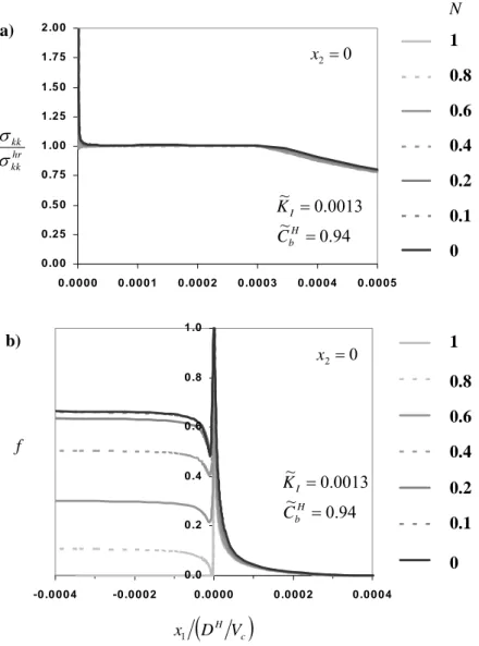
0 .0 0 0 .2 5 0 .5 0 0 .7 5 1 .0 0 1 .2 5 1 .5 0 1 .7 5 2 .0 0 0 .0 0 0 0 0 .0 0 0 1 0 .0 0 0 2 0 .0 0 0 3 0 .0 0 0 4 0 .0 0 0 5 S e rie s 1 S e rie s 2 S e rie s 3 S e rie s 4 S e rie s 5 S e rie s 6 S e rie s 7 hr kk kk σ σ N 1 0.8 0.6 0.4 0.2 0.1 0 a) 0 2= x 0013 . 0 ~ =I K 94 . 0 ~ =H b C 0 .0 0 .2 0 .4 0 .6 0 .8 1 .0 -0 .0 0 0 4 -0 .0 0 0 2 0 .0 0 0 0 0 .0 0 0 2 0 .0 0 0 4 S e rie s1 S e rie s2 S e rie s3 S e rie s4 S e rie s5 S e rie s6 S e rie s7
(
c)
H V D x1 0 2= x b) f 0013 . 0 ~ =I K 94 . 0 ~ =H b C 1 0.8 0.6 0.4 0.2 0.1 0Figure 1. Normalized distributions of (a) stress trace and (b) hydride volume fraction, along the crack plane of a steadily propagating crack, in a zirconium alloy at 300o C, near the sub-critical crack growth threshold.
NEAR-TIP FIELD
Calculations have been performed for Zircaloy-2 and δ-hydride (ZrH1.66) at 300oC. Material
properties are given in [1]. When the velocity of the crack tends to zero and, consequently, the stress intensity factor tends to its threshold value, hydrogen has sufficient time to redistribute in the body and approach chemical equilibrium. Under hydrogen chemical equilibrium and hydride formation governed by (5), the stress trace in the near-tip area of hydride precipitation tends to a constant value [2]:
≅ H b TS e hr hr hr kk C C R V Tln 3x θ σ . (7)
The finite element results, presented in Figure 1a, confirm the existence of the stress trace plateau, within the area of hydride precipitation, shown in Figure 1b. Figure 1b also shows that the hydride phase re-dissolves behind the crack tip, when the material is purely elastic, as expected. On the other hand, material plastic deformation leads to hydride stability, in agreement with experiment observations on zirconium alloys (e.g. [3]).
According to relations (5) and (7) and the finite element calculations, the stress trace plateau does not depend on the elastic-plastic properties of the material, including hardening. Also the plateau stress could take relatively small values, when the remote hydrogen concentration approaches terminal solid solubility. However, hydride cleavage could still occur due to the steep stress increase in the area of large f, very close to the tip (see Figure
1a). Indeed when
(
)
2 21 10 − = < σ σ A K
x I kkhr , 87f >0. and the hoop stress takes values
which exceed hydride strength, assumed to be in the range of 500 to 1000 MPa. Then, a threshold stress intensity factor could be calculated, based on the relation,
σ σ L A K thc hr kk th I = , where th c
L is a critical length of the order of hydride thickness [2]. When
th c
L is in the range of 1 to 5 µm [3], then the predicted value of K is between 5.8 and 13Ith
MPa√m, in agreement with experimental measurements [3].
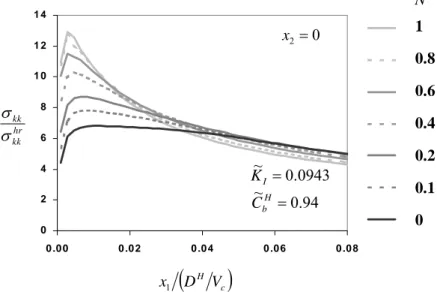
0 2 4 6 8 1 0 1 2 1 4 0 .0 0 0 .0 2 0 .0 4 0 .0 6 0 .0 8 S e rie s1 S e rie s2 S e rie s3 S e rie s4 S e rie s5 S e rie s6 S e rie s7 1 0.8 0.6 0.4 0.2 0.1 0 hr kk kk σ σ 0 2= x 0943 . 0 ~ =I K 94 . 0 ~ =H b C N
(
c)
H V D x1Figure 2. Normalized distributions of stress trace along the crack plane of a steadily propagating crack, in a zirconium alloy at 300o C, within stage-II crack growth regime.
As the normalized stress intensity factor increases, there is no sufficient time for hydrogen to redistribute, within the hydride precipitation zone, due to relatively large crack velocity and/or due to relatively large size of the hydride precipitation zone. Then, the hydrogen in the solid solution is far from chemical equilibrium. In this case there is no thermodynamic requirement on the level of the stress trace in the solid solution. Therefore, when the hydride volume fraction is relatively small, the stress field approaches the asymptotic near-tip field of a hydride-free homogeneous material. For example, in Figure 2, which corresponds to a stage-II crack growth regime, the stress trace distribution is nearly flat close to the crack tip, when the
material does not harden. The maximum equals to 6.81σ0, approaching the hydrogen-free value of 7.11σ0.
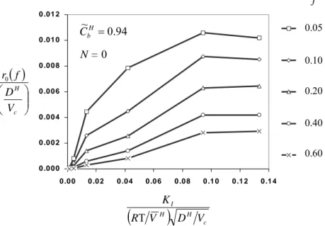
The evolution of the hydride-rich region ahead of the crack tip, r , with 0 K~I is shown
in Figure 3. Note that the ratio
( )
(
c)
HV D f
r0 , for f=0.05-0.6, remains nearly constant, when
0943 . 0 ~ ~ ≥ SS = I I K
K . Based on this feature, one may assume that stage-II delayed hydride
cracking occurs, when the extent of the hydride-rich area, ahead of the crack tip, remains constant, together with the velocity of the crack, and independent of the applied stress intensity factor. If stage-I / stage-II transition is neglected, the velocity of the crack, during stage-II growth, is given by the relation,
(
T~ th)
2I H SS I H SS c D R K V K
V = . Then for a Zircaloy-2
at 300oC and threshold stress intensity factor in the range of 5.8 to 13 MPa√m, one may derive, that the stage-II crack growth velocity is in the range of 3.3⋅10−7 to 1.7⋅10−6m/s; the
predicted range is in agreement with measured crack growth velocities [3].
0 .0 0 0 0 .0 0 2 0 .0 0 4 0 .0 0 6 0 .0 0 8 0 .0 1 0 0 .0 1 2 0 .0 0 0 .0 2 0 .0 4 0 .0 6 0 .0 8 0 .1 0 0 .1 2 0 .1 4 S e rie s5 S e rie s1 S e rie s2 S e rie s3 S e rie s4 94 . 0 ~ =H b C N = 0
( )
c H V D f r0(
)
c H H I V D V R K T 0.20 0.40 0.60 0.10 0.05 fFigure 3. Variation of the extent, ahead of the crack tip and along the crack plane, of the area of hydride precipitation, with hydride volume fraction equal to or larger than f, vs. the normalized stress intensity factor (in a zirconium alloy at 300o C).
REFERENCES
[1] A.G. Varias and A.R. Massih, J. Mech. Phys. Solids, vol. 50, pp. 1469-1510, 2002.
[2] A.G. Varias, ‘Steady-State Crack Growth due to Hydride-Induced Embrittlement – Effect of Hydride Precipitation on Near-Tip Hydrostatic Stress’, Report PA-01-06-02, Malmö University.
[3] P. Efsing and K. Pettersson, Zirconium in the Nuclear Industry: Eleventh International
Symposium, ASTM STP 1295, (Bradley, E.R., Sabol, G.P., Eds.), American Society for