Bone Ingrowth to Ti Fibre Knit Block with High Deformability
Yoko Henmi
1, Yoshihito Naito
2, Ryo Jimbo
3, Yohei Jinno
3, Kazumitsu Sekine
1, Kenichi Hamada
1 1Department of Biomaterials and Bioengineering, Tokushima University Graduate School of Oral Science, Tokushima, Japan. 2Oral Implant Center, Tokushima University Hospital, Tokushima, Japan.3Department of Oral and Maxillofacial Surgery and Oral Medicine, Malmö University, Malmö, Sweden.
Corresponding Author: Yoshihito Naito 3-18-15 Kuramoto-cho, Tokushima, 770-8504 Japan Phone: +81-88-633-7970 Fax: +81-88-633-7461 E-mail: yoshi11@tokushima-u.ac.jp ABSTRACT
Objectives: The objective of this study is to develop a Ti fibre knit block without sintering, and to evaluate its deformability and new bone formation in vivo.
Material and Methods: A Ti fibre with a diameter of 150 μm was knitted to fabricate a Ti mesh tube. The mesh tube was compressed in a metal mould to fabricate porous Ti fibre knit blocks with three different porosities of 88%, 69%, and 50%. The elastic modulus and deformability were evaluated using a compression test. The knit block was implanted into bone defects of a rabbit’s hind limb, and new bone formation was evaluated using micro computed tomography (micro-CT) analysis and histological analysis.
Results: The knit blocks with 88% porosity showed excellent deformability, indicating potential appropriateness for bone defect filling. Although the porosities of the knit block were different, they indicated similar elastic modulus smaller than 1 GPa. The elastic modulus after deformation increased linearly as the applied compression stress increased. The micro-CT analysis indicated that in the block with 50% porosity new bone filled nearly all of the pore volume four weeks after implantation. In contrast, in the block with 88% porosity, new bone filled less than half of the pore volume even 12 weeks after implantation. The histological analysis also indicated new bone formation in the block.
Conclusions: The titanium fibre knit block with high porosity is potentially appropriate for bone defect filling, indicating good bone ingrowth after porosity reduction with applied compression.
Keywords: biocompatible materials; bone formation; bone substitutes; elastic modulus; histological techniques; titanium. Accepted for publication: 23 December 2016
To cite this article:
Henmi Y, Naito Y, Jimbo R, Jinno Y, Sekine K, Hamada K. Bone Ingrowth to Ti Fibre Knit Block with High Deformability J Oral Maxillofac Res 2016;7(4):e2
URL: http://www.ejomr.org/JOMR/archives/2016/4/e2/v7n4e2.pdf doi: 10.5037/jomr.2016.7402
INTRODUCTION
Titanium (Ti) has been widely used in many types of biomedical applications. Some of these applications are bone substitution materials: bone plates, bone screws, artificial joints, and dental implants. Several major advantages of Ti are its excellent biocompatibility, good osteoconductivity, superior corrosion resistivity, and sufficient strength. However, two major disadvantages exist: one is an elastic modulus higher than that of the cortical bone, and the other is a low bone bonding strength without surface modifications. An elastic modulus mismatch leads to “stress shielding” effects and causes bone resorption around the implant [1]. One of the effective approaches to improving upon the above two problems is making the Ti porous. The most popular and traditional process to produce a porous Ti is the sintering of Ti powders [2]. Moreover, a newly developed advanced procedure is selective laser melting [3]. Porous Ti produced by the above-mentioned processes shows a large plastic deformation under compressive stress; however, it shows early fractures without showing sufficient deformation under tensile stress or bending stress. To improve the anisotropic plastic deformation property, a reduction of the porosity is the only solution, resulting in loss of the advantages of porous Ti.
A typical application of bone substitute material is to fill bone defects [4]. Materials commonly used in medical treatment today are calcium-phosphate cement paste [5], bio-absorbable polymer [6], and acrylic resin [7]. The advantage of these materials is that they can be injected into the defect and fill it completely, and the material is geometrically stable in the defect. In contrast, metal materials cannot be injected; therefore, a metal piece for bone defect filling needs to be designed and shaped close to the defect. Some studies reported on the use of porous Ti granules that could fill defects [8,9]. However, since close-packing of the granules into a defect is difficult, a large gap between the granules and bone may inhibit the osteoconduction [10].
Another type of porous Ti that has gained interest is sintered Ti fibre mesh [11-13]. Sintered Ti fibre mesh can exhibit high porosity, sufficient strength, and elastic deformation under bending stress, simultaneously. However, the deformability of sintered Ti fibre mesh is limited, and it needs to be designed and shaped to fill a bone defect. Thus, in this study, a Ti fibre knit block without sintering was developed. The block was produced from a Ti fibre knit tube. The tube was made from one Ti fibre by knitting, and it was
compressed into a block in a metal mould by cold pressing. Because Ti fibre does not bond mutually by sintering, the Ti fibre knit block is flexible and can fit bone defects of any shape. The objective of this study is to evaluate the deformability, apparent elastic modulus, and bone ingrowth of a Ti fibre knit block in vivo.
MATERIAL AND METHODS Fabrication of Ti fibre knit block
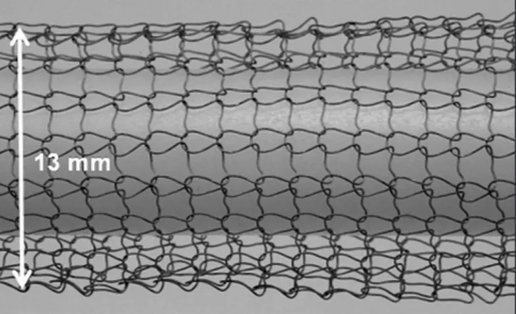
The Ti fibre knit block in this study was produced from grade-1 pure Ti fibre with a diameter of 150 μm. The ultimate strength of the fibre was 400 MPa. Prior to the knitting process, the Ti fibre was soaked in a mixed solution of 10% HF and 40% HNO3 for 1 min to remove its thick surface oxide layer. After soaking, the diameter decreased to approximately 130 μm. One Ti fibre was knitted into a mesh tube of approximately 13 mm in diameter (Figure 1). The knit pattern was a plain stitch with a mesh size of approximately 1.5 mm. The tube was inserted into a metal mould with a 3 mm inner diameter, and compressed to form a cylindrical block of 3 mm in height. In this study, blocks of three different porosities were fabricated. The porosity was adjusted to approximately 90% (Group A), 70% (Group B), and 50% (Group C) by controlling the length of the Ti mesh tube. The Ti fibre volume in a block was calculated from the weight of the block and Ti density, and the porosity of the block was calculated from the Ti fibre volume and apparent volume of the block with a 3 mm diameter and 3 mm height. Ti fibre knit blocks for animal study were sterilized by ethylene oxide gas.
Mechanical property evaluation
To evaluate the elastic modulus and deformability, compressive stress was applied to the block using a universal testing instrument (Autograph AG-1KNX, Shimadzu, Kyoto, Japan). The loading direction
was parallel to the cylinder axis, and the strain rate was 1 × 10⁻²·s-1. Because the block showed a large
plastic deformation with loading, and the elastic modulus changed with increasing plastic deformation, the applied stress to the block started at 5 N and increased to 50 N in 5-N steps. To clarify the change in plastic deformation after loading, two loading-unloading cycles were performed at each applied stress. Young’s modulus of the block was calculated from the inclination of the linear unloading area of the stress-strain curve. To calibrate the displacement of the compressive test apparatus with loading, a copper rod of the same dimensions as the Ti knit block was loaded, and the strain of the test apparatus was cancelled. The deformation of the Ti knit block during the compressive test was observed and recorded with a digital camera.
Surgical procedure
New bone formation was evaluated using 16 New Zealand white rabbits, following the requirements of the Ethics Committee for Animal Research (protocol no. 00391.01) at the École Nationale Vétérinaire d’Alfort (Maisons-Alfort, Val-de-Marne, France). All surgical procedures were performed under general anaesthesia using an intramuscular injection of ketamine chlorate (15 mg/kg). The tibia of the rabbit was shaved and disinfected with 10% povidone-iodine solution. After anaesthetic and disinfection procedures, a flap was raised, and three bone defects of 3 mm
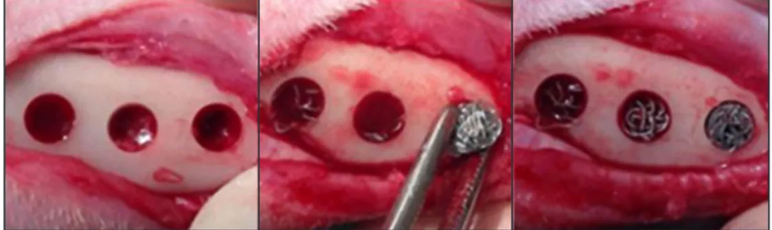
in depth and 3 mm in diameter were drilled in each tibia in imitation of the similar study on the bone scaffolds fabricated by Ti fibre [14]. The bone defects were randomly designated to the specimen from the three porosities (Figure 2).
Micro computed tomography
Four weeks or 12 weeks after implantation, the animals were euthanized with an anaesthesia overdose, and the bone around the defects was cut out. The bone specimens were removed en bloc and were soaked in 4% formaldehyde. After fixation, the bone formation within the defect was examined using micro-CT (SkyScan 1176, Bruker microCT, Kontich, Belgium). All scans were obtained at 80 kV and 300 mA, using a Cu + Al filter. The image pixel size was 17.59 µm. Three-dimensional images were created using reconstruction software (NRecon, Bruker microCT, Kontich, Belgium), and analysed using viewing software (Data Viewer, Bruker microCT, Kontich, Belgium). The axis of the slice was set perpendicular to the axis of the defect. The cylindrical volume of interest (VOI) was 3 mm in diameter and 3 mm in height, and 200 slices in height were created. The volume of the newly formed bone in the defect was evaluated using analysis software (CT-Analyser, Bruker micro CT, Kontich, Belgium). The upper threshold of the signal intensity was set to 85/256 to eliminate existing bone in the image, and the lower threshold of the signal intensity was set to 25/256 to eliminate Ti fibre and pores in the image (Figure 3).
Figure 2. Implantation of Ti fibre knit block into bone defects. In this picture, blocks of groups A, B, and C were implanted from left to right.
The volume fraction of the newly formed bone in each defect area was calculated using the following equation:
Vnb = Volume of newly formed bone Volume of bone defect
where Vnb is the volume fraction of the newly formed bone.
Histological analysis
After CT scanning, the bone specimens were dehydrated and infiltrated in a series of mixed liquid of ethanol and a light curing resin (Technovit 7200 VLC, Heraeus Kulzer GmbH, Hanau, Germany) with an ethanol mixing ratio of 100%, 70%, 50%, 30%, 15%, and 0% under constant vacuuming. After complete infiltration, the specimens were embedded in light curing resin (Technovit 7200 VLC, Heraeus Kulzer GmbH, Hanau, Germany). The resin blocks after curing were subjected to a non-decalcified cut using a low-speed diamond band saw (BS-300CP, Meiwafosis Co., LTD, Tokyo, Japan), and then grind sectioning using waterproof silicon carbide grinding paper of P800, P1000, and P1200 with a final thickness of approximately 30 µm at the central section. The cutting direction was parallel to the cylindrical specimen axis. The specimen was then stained with toluidine blue according to staining protocol for plastic sections. Histological analyses were performed using a light microscope (BZ-9000E; KEYENCE, Osaka, Japan). The images were analysed using image analysing software (Image J ver. 1.43u, National Institute of Health, Maryland, U.S.A.), and the amount of newly formed bone stained with toluidine blue in the bone defect area was calculated.
The area fraction of the newly formed bone in the defect area was calculated using the following equation:
Snb = Area of newly formed bone Area of bone defect
where Snb is the area fraction of the newly formed bone.
Statistic analysis
All data were statistically analysed using a student’s t-test (Microsoft Excel 2010, Microsoft, Redmond, WA, USA), and P value of less than 0.01 was considered for significance.
RESULTS
Morphology and porosity of Ti fibre knit block
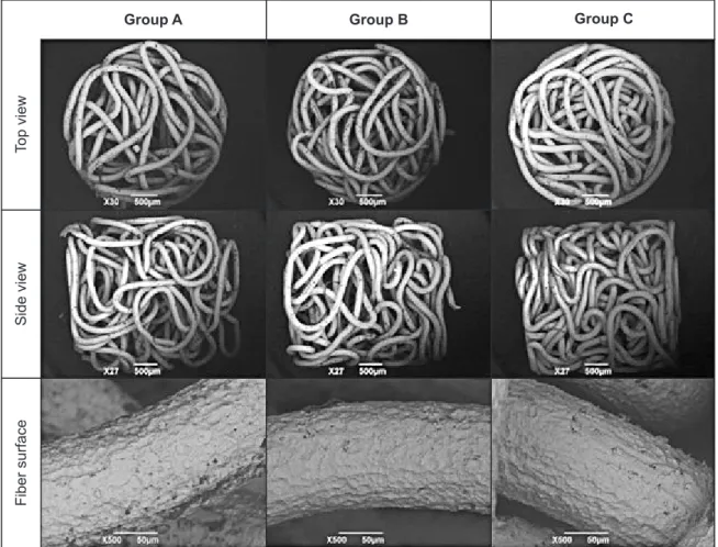
The fabricated Ti fibre knit blocks are shown in Figure 4. The Group A specimen with the highest porosity showed loosely compacted Ti fibre, while the Group C specimen with the lowest porosity showed densely compacted fibre. No fibre folding or fractures were observed in the SEM images of each block (Figure 5). The SEM images also showed a rough surface of Ti fibre after the surface oxide layer was removed; however, no cracks were observed.
The porosities of the blocks of groups A, B, and C were 88%, 69%, and 50%, respectively. Although pore size distribution was not estimated in this research, many large pores were observed in the Group A specimen, while few large pores were observed in the Group C specimen.
Figure 4. Appearance of Ti fiber knit blocks.
Group A Group B Group C
Side view
Mechanical properties of Ti fibre knit block
Figure 6 shows the stress-strain curves of the compressive test for the Ti fibre knit block. The Group A specimen showed a large plastic deformation with the first loading of 5 N, 10 N, and 15 N. This specimen showed less plastic deformation with the second loading of the forces; however, it showed considerable hysteresis between loading and unloading. The plastic deformation decreased with a loading of more than 20 N, and the difference in the stress-strain curve between the first loading and second loading also decreased. A unique feature of the stress-strain curves was that a linear area was barely observed in the loading curve; however, the initial area of the unloading curve was linear and appropriate for Young’s modulus calculation. The Group B specimen showed a smaller plastic deformation than the Group A specimen; however, the reduction in the plastic deformation with increasing applied stress was smaller than that of the Group B specimen. The Group C specimen showed a much smaller plastic deformation. The deformation of groups A, B, and C with a 50 N load was 2.49 mm, 1.95 mm, and 0.63 mm, respectively. The plastic deformation after unloading of a 50 N load was 2.26 mm, 1.68 mm, and 0.38 mm, respectively.
Figure 7 shows the Ti fibre knit blocks after a loading of 50 N. The Group A specimen showed a large deformation in the directions perpendicular and parallel to the specimen axis. This buckling was slightly observed in the Group B specimen, and barely observed in the Group C specimen.
Figure 8 shows Young’s modulus of the Ti fibre knit block. Although the porosities of the specimens were different, Young’s modulus of the specimens of groups A, B, and C were not significantly different. Young’s modulus of the specimen increased linearly with an increasing applied load.
Micro computed tomography analysis
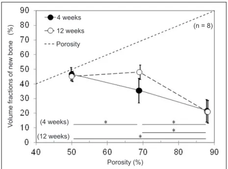
The effects of specimen porosity and time after implantation on a volume fraction of new bone (Vnb) are shown in Figure 9. A dotted line indicates the porosity, namely, the maximum Vnb at the porosity. Four weeks after implantation, the Group C specimen with 50% porosity showed the highest Vnb (46.7%), and new bone filled nearly all pores. With increasing porosity, Vnb decreased. Twelve weeks after implantation, Vnb of the Group C specimen (45.2%) did not increase because new bone already filled nearly all of the pores at four weeks after implantation.
Group A Group B Group C
Fiber surface
Side view
Top view
Figure 6. Compressive stress-strain curve of Ti fiber knit block.
Figure 7. Ti fiber knit block after loading of 50 N. Dotted line indicates the original height.
Group A Group B Group C
Group A Group B Group C Strain (%) Strain (%) Strain (%) Stress (MPa) Stress (MPa) Stress (MPa)
Vnb of the Group B specimen with a 69% porosity (35.5%) increased from that at four weeks after implantation, and had a Vnb similar to that of Group C; however, new bone did not fill all pores. Vnb of the Group A specimen with an 88% porosity (21.7%) did not increase from that at four weeks after implantation.
Histological evaluation
Typical histological cross-section images of the blocks at four weeks and 12 weeks after implantation are shown in Figure 10. Area stained with light blue shows an existing bone, and area stained with dark blue shows a new bone. The histological observation showed healing of the bone around the Ti fibre knit block, and did not show an inflammatory response in any specimens. New bone formation in the Group A specimen of 88% porosity was limited to the area near the tibia bone surface. New bone formation in the Group B specimen and Group C specimen were observed in the entire Ti fibre knit block.
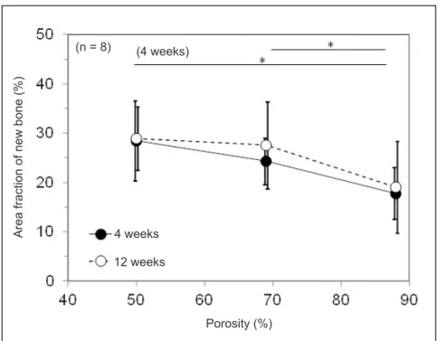
Figure 11 shows Snb of the Ti fibre knit block as histologically evaluated. Four weeks after implantation, Snb of the Group A specimen (17.8%) was significantly lower than that of the Group C specimen (28.4%). Twelve weeks after implantation, Snb of the Group A (19.1%), Group B (27.6%), and Group C specimens (28.9%) was not significantly different. Interestingly, although the dependence of porosity on Snb as histologically evaluated was similar to that of Vnb evaluated using CT data, Snb was clearly lower than that evaluated using CT data.
DISCUSSION
Morphology and mechanical properties of Ti fibre knit block
The Ti fibre knit block developed in this research is made of a single fibre, and no fibre fracture was observed in the blocks. Therefore, there are only two
fibre ends in the block. Because the diameter of the fibre is small, the fibre ends can potentially penetrate tissue and cause inflammation. The risk of such trouble in this block is, however, minimum, because there are minimum numbers of fibre ends.
Because the Ti mesh tube was compressed to the cylindrical block, nearly all parts of the fibre in the block are not straight, and the directions of each part are not uniform, as observed in Figure 4 and Figure 5. Therefore, the deformations in each part with loading should not be uniform. When parts of the fibre are oriented nearly perpendicular to the block axis, the deformation in the loading direction should be small with initial loading. By contrast, when parts of the fibre are oriented nearly parallel to the block axis, the deformation should be large with initial loading. Because the fibre of the Group A specimen was lightly compressed, the directions of the parts of the fibre were potentially close to random. Therefore, many parts of the fibre were oriented close to parallel
to the block axis, and showed large deformations with initial loading. By contrast, because the fibre of the Group C specimen was heavily compressed, many parts of the fibre were potentially oriented perpendicular to the block axis, and showed small deformations with initial loading.
Although the initial loading curves of the block were not linear, the initial unloading curves were linear. Macroscopically, linear elastic recovery is a typical behaviour; however, it is not certain that the recovery of each part of the fibre is also linear. The mechanism of linearity mismatches between loading and unloading was not clarified in this research. However, the pairing of nonlinear loading curves and linear unloading curves reminds us of the loading Figure 8. Young’s modulus of Ti fiber knit block.
Figure 9. Volume fractions of new bone 4 weeks and 12 weeks after implantation.
*Significant different (P < 0.01).
Porosity (%)
Volume fractions of new bone (%)
Porosity 12 weeks 4 weeks (n = 8) (12 weeks) (4 weeks) Stress (MPa) Young’ s modulus (GPa) (n = 5) Group A (88%) Group B (69%) Group C (50%)
and unloading curves of a dynamic hardness test result [15], and suggests this is not necessarily unusual behaviour.
One more unusual mechanical behaviour was observed in this research. It is reported that the elastic modulus of the porous Ti decreased as the porosity increased [16]. However, the elastic modulus of the block in this research did not change when the porosity changed. The reason for this decreased
effect of porosity is also the orientation of the parts of the fibre in the block. The parts of the fibre close to perpendicular to the block axis show less deformation with loading; therefore, the number density of parts of the fibre parallel to the block axis mainly affects the elastic modulus. As discussed above, major parts of the shorter fibre of the Group A specimen, and minor parts of the longer fibre of the Group C specimen, were potentially parallel to the axis. Figure 10. Typical histological cross section images of the blocks (Toluidine blue stain, original magnification x10).
Figure 11. Area fraction of new bone 4 weeks and 12 weeks after implantation.
*Significant different (P < 0.01).
Group A Group B Group C
12 weeks
4 weeks
Porosity (%)
Area fraction of new bone (%)
12 weeks 4 weeks (4 weeks) (n = 8) 500 μm 500 μm 500 μm 500 μm 500 μm 500 μm
For the three types of blocks in this research, the number densities of the parts of the fibre parallel to the block axis were potentially similar, and the elastic modulus were similar.
After the plastic deformation of the compressive test, each specimen indicated compressive plastic deformation along the block axis. The compressive deformation induced a porosity reduction, and potentially led to an increase in elastic modulus. It is noted that the compressive deformation during block production did not change the elastic modulus of each type of specimen. The difference in the above two compressive deformations was that the block was produced in a mould and there was a wall beside it, while the block was deformed freely perpendicular to the block axis during the compressive test. However, the effect of this difference was not clarified in this research.
To discuss the mechanical behaviour of the blocks quantitatively, a three-dimensional analysis of the fibre shape in the block is required. However, a numerical analysis is still difficult because the shape of the fibre is complicated, and the shape should be different in each block.
Increasing the porosity of the block increased the plastic deformation after 50 N loading. In addition, the direction of deformation changed. The Group A specimen showed buckling with plastic deformation, in other words, it showed deformation parallel to and perpendicular to the loading direction, simultaneously. However, the Group C specimen showed only plastic deformation parallel to the block axis. Flexible plastic deformation of a high-porosity block suggests that these blocks should fill a non-uniform bone defect effectively with compression into the defect. By contrast, limited plastic deformation of a low-porosity block suggests that these blocks might be appropriate to fill a cylindrical defect but are not appropriate for non-uniform defects, especially a defect whose entrance size is smaller than the inner size.
Bone formation of Ti fibre knit block
Both the X-ray micro-CT analysis and histological analysis indicated new bone formation in the blocks; however, Snb based on a histological analysis was lower than Vnb based on an X-ray micro-CT analysis. One possible reason was that the histological sections in this study were sliced parallel to the block axis. Because the new bone grew into the block from the outside, Vnb in the outer area of the block is higher than or similar to that of the inner area. Therefore, when the sections were sliced perpendicular to
the axis, Snb should have been close to Vnb of the entire specimen. When the sections were sliced parallel to the block axis, Snb changes with the slice position. Therefore, Snb is not necessarily close to Vnb. The mismatch between Vnb and Snb suggests a limitation of the histological analysis in this research, and the efficacy of X-ray micro-CT analysis.
The Ti fibre knit block with higher porosity showed less bone formation in this research. There are many research studies that indicate the effect of the pore size of porous material on bone formation [17-25], and they suggest there is an appropriate range of pore sizes. However, the proper size seems to be under discussion. In this research, the pore size distribution could not be analysed from X-ray micro-CT data. However, the results potentially indicated that the Group C specimen consisted of pores of appropriate size, and the pore size of the Group A specimen was larger than that. This leads to a difference in new bone formation speed between the types of specimen.
Appropriate porosity of Ti fibre knit block
The deformation of the specimen after the compressive test suggested the porosity should decrease after compression. Therefore, the Group A specimen, which had the lowest bone formation in this research, could increase its bone formation after compression into a bone defect. Concerning the other important clinical property, deformability with compression, the Group A specimen indicated promising data. Therefore, the Group A specimen, a specimen with high porosity and high deformability, is appropriate for bone defect filling. After filling into the defect, the porosity should decrease and the bone formation should be improved, simultaneously. The effect of in situ porosity changes with bone defect filling will be evaluated in the future.
CONCLUSIONS
The titanium fibre knit block in this research exhibited excellent properties with controlling porosity of the block. The specimen of higher porosity indicated excellent deformability, demonstrating potential appropriateness for bone defect filling material. The elastic modulus was sufficiently smaller than that of bone. The titanium fibre knit block with 88% porosity is potentially appropriate for bone defect filling, potentially indicating good bone ingrowth after porosity reduction with compression into it.
ACKNOWLEDGMENTS AND DISCLOSURE STATEMENTS
The authors are grateful to Marui Textile Machinery Co., Ltd., Osaka, Japan, for the Ti fibre
knit block production, which was supported in part by a manufacturing grant from the Small and Medium Enterprise Agency, Japan.
The authors report no conflicts of interest related to this study.
REFERENCES
1. Huiskes R, Weinans H, van Rietbergen B. The relationship between stress shielding and bone resorption around total hip stems and the effects of flexible materials. Clin Orthop Relat Res. 1992 Jan;(274):124-34. [Medline: 1728998]
2. Wang X, Xu S, Zhou S, Xu W, Leary M, Choong P, Qian M, Brandt M, Xie YM. Topological design and additive manufacturing of porous metals for bone scaffolds and orthopaedic implants: A review. Biomaterials. 2016 Mar;83: 127-41. [Medline: 26773669] [doi: 10.1016/j.biomaterials.2016.01.012]
3. Sallica-Leva E, Caram R, Jardini AL, Fogagnolo JB. Ductility improvement due to martensite α’ decomposition in porous Ti-6Al-4V parts produced by selective laser melting for orthopedic implants. J Mech Behav Biomed Mater. 2016 Feb;54:149-58. [Medline: 26458113] [doi: 10.1016/j.jmbbm.2015.09.020]
4. Liu Y, Lim J, Teoh SH. Review: development of clinically relevant scaffolds for vascularised bone tissue engineering. Biotechnol Adv. 2013 Sep-Oct;31(5):688-705. [Medline: 23142624] [doi: 10.1016/j.biotechadv.2012.10.003]
5. Zhang J, Liu W, Schnitzler V, Tancret F, Bouler JM. Calcium phosphate cements for bone substitution: chemistry, handling and mechanical properties. Acta Biomater. 2014 Mar;10(3):1035-49. [Medline: 24231047] [doi: 10.1016/j.actbio.2013.11.001]
6. LogithKumar R, KeshavNarayan A, Dhivya S, Chawla A, Saravanan S, Selvamurugan N. A review of chitosan and its derivatives in bone tissue engineering. Carbohydr Polym. 2016 Oct 20;151:172-88. [Medline: 27474556] [doi: 10.1016/j.carbpol.2016.05.049]
7. Magnan B, Bondi M, Maluta T, Samaila E, Schirru L, Dall’Oca C. Acrylic bone cement: current concept review. Musculoskelet Surg. 2013 Aug;97(2):93-100. [Medline: 23893506] [doi: 10.1007/s12306-013-0293-9]
8. Vandeweghe S, Leconte C, Ono D, Coelho PG, Jimbo R. Comparison of histological and three-dimensional characteristics of porous titanium granules and deproteinized bovine particulate grafts used for sinus floor augmentation in humans: a pilot study. Implant Dent. 2013 Aug;22(4):339-43. [Medline: 23736312] [doi: 10.1097/ID.0b013e3182938d03] 9. Thor A. Porous Titanium Granules and Blood for Bone Regeneration around Dental Implants: Report of Four Cases
and Review of the Literature. Case Rep Dent. 2013;2013:410515. [Medline: 23533827] [PMC free article: 3606741] [doi: 10.1155/2013/410515]
10. Akimoto K, Becker W, Persson R, Baker DA, Rohrer MD, O’Neal RB. Evaluation of titanium implants placed into simulated extraction sockets: a study in dogs. Int J Oral Maxillofac Implants. 1999 May-Jun;14(3):351-60. [Medline: 10379108]
11. Kitaoka K, Yamamoto H, Tani T, Hoshijima K, Nakauchi M. Mechanical strength and bone bonding of a titanium fiber mesh block for intervertebral fusion. J Orthop Sci. 1997 Mar;2(2):106-13. [doi: 10.1007/BF02489521]
12. Vehof JW, Spauwen PH, Jansen JA. Bone formation in calcium-phosphate-coated titanium mesh. Biomaterials. 2000 Oct;21(19):2003-9. [Medline: 10941922]
13. Hirota M, Shima T, Sato I, Ozawa T, Iwai T, Ametani A, Sato M, Noishiki Y, Ogawa T, Hayakawa T, Tohnai I. Development of a biointegrated mandibular reconstruction device consisting of bone compatible titanium fiber mesh scaffold. Biomaterials. 2016 Jan;75:223-36. [Medline: 26513415] [doi: 10.1016/j.biomaterials.2015.09.034]
14. Yasuoka S, Usukura Y, Fuse M, Okada H, Hayakawa T, Kato T. Stainless and titanium fibers as non-degradable three-dimensional scaffolds for bone reconstruction. J Hard Tissue Biol. 2014 Jul;23(4):407-14. [doi: 10.2485/jhtb.23.407] 15. Sahin O, Uzun O, Sopicka-Lizer M, Gocmez H, Kölemen U. Dynamic hardness and elastic modulus calculation of
porous SiAlON ceramics using depth-sensing indentation technique. J Eur Ceram Soc. 2008 Dec;28(6):1235-42. [doi: 10.1016/j.jeurceramsoc.2007.09.052]
16. Bandyopadhyay A, Espana F, Balla VK, Bose S, Ohgami Y, Davies NM. Influence of porosity on mechanical properties and in vivo response of Ti6Al4V implants. Acta Biomater. 2010 Apr;6(4):1640-8. [Medline: 19913643] [PMC free article: 2830321] [doi: 10.1016/j.actbio.2009.11.011]
17. Chang B, Song W, Han T, Yan J, Li F, Zhao L, Kou H, Zhang Y. Influence of pore size of porous titanium fabricated by vacuum diffusion bonding of titanium meshes on cell penetration and bone ingrowth. Acta Biomater. 2016 Mar;33: 311-21. [Medline: 26802441] [doi: 10.1016/j.actbio.2016.01.022]
18. Bobyn JD, Pilliar RM, Cameron HU, Weatherly GC. The optimum pore size for the fixation of porous-surfaced metal implants by the ingrowth of bone. Clin Orthop Relat Res. 1980 Jul-Aug;(150):263-70. [Medline: 7428231]
19. Park JW, Kim ES, Jang JH, Suh JY, Park KB, Hanawa T. Healing of rabbit calvarial bone defects using biphasic calcium phosphate ceramics made of submicron-sized grains with a hierarchical pore structure. Clin Oral Implants Res. 2010 Mar;21(3):268-76. [Medline: 20074242] [doi: 10.1111/j.1600-0501.2009.01846.x]
20. Geetha M, Singh AK, Asokamani R, Gogia AK. Ti based biomaterials, the ultimate choice for orthopaedic implants – A review. Progress in Materials Science. 2009 May;54(3):397-425. [doi: 10.1016/j.pmatsci.2008.06.004]
21. Karageorgiou V, Kaplan D. Porosity of 3D biomaterial scaffolds and osteogenesis. Biomaterials. 2005 Sep;26(27): 5474-91. [Medline: 15860204]
22. Ripamonti U. Osteoinduction in porous hydroxyapatite implanted in heterotopic sites of different animal models. Biomaterials. 1996 Jan;17(1):31-5. [Medline: 8962945] [doi: 10.1016/0142-9612(96)80752-6]
23. Dabrowski B, Swieszkowski W, Godlinski D, Kurzydlowski KJ. Highly porous titanium scaffolds for orthopaedic applications. J Biomed Mater Res B Appl Biomater. 2010 Oct;95(1):53-61. [Medline: 20690174] [doi: 10.1002/jbm.b.31682]
24. Li JP, Habibovic P, van den Doel M, Wilson CE, de Wijn JR, van Blitterswijk CA, de Groot K. Bone ingrowth in porous titanium implants produced by 3D fiber deposition. Biomaterials. 2007 Jun;28(18):2810-20. [Medline: 17367852] 25. Prananingrum W, Naito Y, Galli S, Bae J, Sekine K, Hamada K, Tomotake Y, Wennerberg A, Jimbo R, Ichikawa T. Bone
ingrowth of various porous titanium scaffolds produced by a moldless and space holder technique: an in vivo study in rabbits. Biomed Mater. 2016 Feb 2;11(1):015012. [Medline: 26836201] [doi: 10.1088/1748-6041/11/1/015012]
To cite this article:
Henmi Y, Naito Y, Jimbo R, Jinno Y, Sekine K, Hamada K. Bone Ingrowth to Ti Fibre Knit Block with High Deformability J Oral Maxillofac Res 2016;7(4):e2
URL: http://www.ejomr.org/JOMR/archives/2016/4/e2/v7n4e2.pdf doi: 10.5037/jomr.2016.7402
Copyright © Henmi Y, Naito Y, Jimbo R, Jinno Y, Sekine K, Hamada K. Published in the JOURNAL OF ORAL & MAXILLOFACIAL RESEARCH (http://www.ejomr.org), 28 December 2016.
This is an open-access article, first published in the JOURNAL OF ORAL & MAXILLOFACIAL RESEARCH, distributed under the terms of the Creative Commons Attribution-Noncommercial-No Derivative Works 3.0 Unported License, which permits unrestricted non-commercial use, distribution, and reproduction in any medium, provided the original work and is properly cited. The copyright, license information and link to the original publication on (http://www.ejomr.org) must be included.