This is the published version of a paper published in Wireless personal communications.
Citation for the original published paper (version of record):
Abbas, M T., Muhammad, A., Song, W-C. (2019)
Road-Aware Estimation Model for Path Duration in Internet of Vehicles (IoV)
Wireless personal communications
https://doi.org/10.1007/s11277-019-06587-5
Access to the published version may require subscription.
N.B. When citing this work, cite the original published paper.
This article is distributed under the terms of the Creative Commons Attribution 4.0
International License (http://creativecommons.org/licenses/by/4.0/), which permits
unrestricted use, distribution, and reproduction in any medium, provided you give
appropriate credit to the original author(s) and the source, provide a link to the Creative
Commons license, and indicate if changes were made.
Permanent link to this version:
Road‑Aware Estimation Model for Path Duration in Internet
of Vehicles (IoV)
Muhammad Tahir Abbas1 · Afaq Muhammad2 · Wang‑Cheol Song3 © The Author(s) 2019
Abstract
In Internet of Vehicles (IoV), numerous routing metrics have been used to assess the per-formance of routing protocols such as, packet delivery ratio, throughput, end-to-end delay and path duration. Path duration is an influential design parameter, among these routing metrics, that determines the performance of vehicular networks. For instance, in highly dynamic scenarios, it can be used to predict link life time in on-demand routing protocols. In this paper, we propose an infrastructure-assisted hybrid road-aware routing protocol which is capable of enhanced vehicle-to-vehicle and vehicle-to-infrastructure communica-tion. A remarkable aspect of the proposed protocol is that it establishes a link between path duration and fundamental design parameters like vehicular velocity, density, hop count and transmission range. Although, a lot of research has been previously performed, a well defined analytical model for IoV is not available in the literature. Precisely, a relation between path duration and vehicular velocity has not been validated in the previous studies. Experimental results show that the increased packet delivery ratio with reduced end-to-end delay can be achieved by the prediction of path duration. Proposed model for path duration is validated by getting experimental results from network simulator 3 (NS3) and analytical results from MATLAB. In addition, SUMO simulator was used to generate real time traffic on the roads of Gangnam district, South Korea.
Keywords Internet of Vehicles (IoV) · Infrastructure-assisted network · Inter-vehicle communication · Hybrid road-aware routing · Roadside units (RSUs) · Path duration estimation
* Muhammad Tahir Abbas tahir.abbas@kau.se
Afaq Muhammad afaq.csit@suit.edu.pk
Wang-Cheol Song philo@jejunu.ac.kr
1 Department of Computer Science, Karlstad University, Karlstad, Sweden
2 Department of Computer Science and IT, Sarhad University of Science and Information Technology, Peshawar, Pakistan
1 Introduction
With a phenomenal increase in the number of vehicles on roads, IoV has become one important research field providing better solutions for smart transportation system. Cur-rently, researchers are focusing mainly on the architecture and development of IoV and its applications due to its significance in an Intelligent Transportation System (ITS). Pre-ciesely, IoV applications allow for improving road safety features such as intersection warning, crash warning, safe distance warning, and so on. Not only that, such applications also provide real-time entertainment services. Nevertheless, these road safety applica-tions require appropriate propagation of warning messages which is a difficult task on the road owing to vehicular dynamic environment. Although, there are a number of routing protocols [1–3] that enable a vehicle to find a better path for information sharing, a path becomes invalid if a vehicle changes its topology even slightly. It is pertinent to mention here that the prediction of a path failure before it breaks as well as finding a new path can significantly enhance the performance of the network. To this end, in the paper, we propose a novel analytical model for the estimation of path duration with road-aware routing pro-tocol to enhance the packet delivery ratio with reduced routing overhead and end-to-end delay.
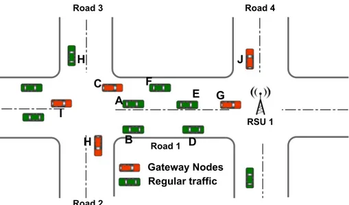
Number of commercial and safety applications need coordination among cars and Road-side Units (RSUs) [4–6]. However, RSUs not provide safety application services but to provide routing functionalities as well, with the aim of reducing overhead. RSU-based routing protocols are termed as infrastructure-assisted protocols [7–10]. These protocols are responsible for relaying data traffic to remote vehicles in sparse or detached networks. Although, several studies that have been conducted on this routing apraoch can be found in the literature, it is still in its inception. A number of previously proposed protocols undergo low readability and inadequacy while negotiating with both (V2I) and (V2V) communica-tion [7, 8]. Previously proposed protocols do not meet diverse requirements for V2I com-munication, as they are not designed specifically for the hybrid environments, as shown in Fig. 1.
Prediction of path for a specific time period is not straightforward as it relies on multi-ple parameters such as velocity, direction, position of a vehicle and number of relay nodes [11, 12]. Path duration is defined as the total time for which two nodes remain connected through relay nodes. A number of distinguished routing protocols discussed in [13, 14] do not select a route based on its duration. Hence, the ability of estimating a path lifetime, if incorporated, will substantially increases the throughput of a routing protocol.
In this paper, a novel infrastructure-based hybrid road-aware routing protocol (IARAR) is proposed along with an analytical model for path duration estimation to eliminate the aforementioned restraints of V2V and V2I communication. In order to that, IARAR com-bines the features of reactive and proactive routing simultaneously. V2V and V2I connec-tion is established by the usage of RSUs at intersecconnec-tions or in a multi-hop fashion, based on available paths. A route within a road segment is determined by the estimation of path duration using different parameters including hop count, link availability time, vehicle velocity and direction. A relation of node relative velocity is derived along with the prob-ability functions to realize almost each scenario of vehicular movement for better path cal-culation. The approach of local information distribution improves the process of link dis-covery as well as reduces the extra overhead over wireless and wired network. Last but not least, our proposed mathematical model for path estimation guarantees link reliability and stability for a road segment.
The rest of the paper is organized as follows: Sect. 2 describes the related work of exist-ing routexist-ing protocols for infrastructure-assisted VANETs. Section 3 presents functionality of the proposed protocol. Section 4 shows different operations of IARAR along with route estimation model to be used for the data transmission within a road segment. Section 5
assess the performance of our proposed estimation model and routing protocol. Section 6
concludes the paper.
2 Related Work
VANET applications vary from situation to situation in vehicular networks such as warn-ing messages for collision avoidance, emergency operations and sometimes multimedia services and voice over IP applications. These communication-based VANET applications cover both V2V and V2I communication modes. Motivation behind utilizing the infrastruc-ture (RSUs) is due to their fixed positions. These nodes (RSU) provide route access with very little administrative overhead in comparison to the scenario where both the nodes are mobile. It is worth mentioning that RSUs are connected through links with a small delay, high bandwidth and a low error rate. Different studies based on infrastructure-assisted routing protocols prove their superiority upon other available protocols while considering the overall performance [8]. In [15], Dharani et al. have presented an intersection-based connectivity-aware protocol for an urban environment. Shortest path algorithm is used to
information. Proposed protocol selects the shortest by considering the traffic conditions and vehicle mobility.
A position-based routing protocol is proposed in [2]. Improved data packet deliv-ery with reduced delay is achieved by taking optimized broadcast into account. In order to forward the packet to its neighbor segment, iCAR [2] analyzes neighbor segment for minimum delay, less distance towards the destination, and a higher number of vehicles. iCAR II [3], an enhanced version of iCAR [2], has an improved packet delivery ratio. This improved ratio is obtained by the periodically broadcast of beacons up to one hop to update road conditions. Every vehicle in [3] is assumed to be equipped with Global Positioning System (GPS) and further assistance is provided by the fixed infrastructure.
Authors in [16] proposed a road network connectivity aware routing protocol with the consideration of traffic lights and vehicle density at the road. Selection of next forwarding node is done by the microscopic greedy selection technique while ensuring lower delay, high throughput, and efficiency. RSUs near the intersections collect the vehicle information through unicast data packets. Packet forwarding through RSU is done in two steps: Divid-ing the section based on its connectivity, and establishment of the road connectivity-aware model. Traffic light plays an important role in the vehicular movement in the presence of RSUs, however, the connectivity to RSU and a path recovery process is weak or is missing from the paper.”
In [9, 10], vehicular network topology is further divided into smaller regions named as sectors. Each sector is served by one or more RSUs. Inside the segment, data is transmitted in a multi-hop fashion, while the Inter-sector communication is supported by the respective RSUs. The main reason of splitting network topology into sectors is to minimize either the management of a table for vehicle position for joined sectors as presented in [9], or a region for route discovery (specifically in [9], and [10]). Authors in [17] proposed another sector-based protocol with the consideration of new localization strategy between the inter-sections. Furthermore, in order to maintain QoS for each link, four parameters are con-sidered and a path reliability is estimated before sending the data over that link. The way IHRAR differs from IARAR is that in IHRAR, the problem of RSU failure and its recovery process is not considered as well as finding the shortest path for data forwarding with its mathematical model is not available. To this end, this paper extends our previous research [17] with the addition of a detailed framework from our previously IHRAR protocol. RSU selection, RSU disruption, process of route request/response through fixed infrastructure are discussed. Moreover, a mathematical model is proposed in this paper to find a stable path. Use cases for a relative velocity with their probability functions and its effectiveness are explored to meet the challenges of modern world.
These infrastructure-assisted routing protocols vary marginally in vehicle localiza-tion and inter-sector data propagalocaliza-tion, but differ significantly within the sectors. In addi-tion, these infrastructure-assisted routing strategies primarily depend on the total number of installed RSUs on their locations. Moreover, the comprehensive performance of these strategies, network overhead and latency rate entirely depend on the total size of zone. Last but not least, physical distribution of immense number of RSUs are not always feasible owed to large maintenance expense. From the above discussion, it can be concluded that there is a huge demand for new infrastructure-assisted protocols that enable both modes of communications, i.e. V21 and V2V.
In IoV, stable path always plays a significant role in order to gain better performance. Initial attempts have been made in [18] for path duration in MANETs. Path lifetime with improved link stability are analyzed in [19]. In addition, a phenomenon of ’Edge Effect’ is discussed by the authors, which occurs in dense networks. In these scenarios, neigh-bor vehicles are available immediately for next-hop node at a brink of transmission range. Hence, a small movement of vehicle causes link breakage by going outside the transmis-sion range, results downgrade the performance of the protocol.
Path estimation holds various essential parameters, such as transmission range, rela-tive velocity and hop count [20]. Importance of path duration in MANETs for reactive approach has also been discussed. In [21], a new approach is investigated to propose a relation between link distance and number of hops. In this approach, in order to select a relay node, an assumption is made to select a relay node based on least remaining distance (LRD). With the selection of various paths with long life, [22] shows positive results for multiple use cases. Authors find out that the path duration estimation is imperative for dis-covering paths with durable life.
In [20], authors study the correlation between throughput and path duration along with the estimation model for numerous mobility scenarios and probability density functions of remaining link life. Investigated mobility model includes Random waypoint model (RWP), Reference point group model (RPGM), Manhattan and Freeway. Authors conclude that the node density is an imperative design parameter for a durable path. However, a relationship between the two could not be established. To communicate this relation, a detailed math-ematical model was still needed, which is provided in this paper.
Aim of our research is to improve the routing strategies for infrastructure-assisted vehic-ular networks by proposing IARAR with more durable communication links. In the pro-posed protocol, roads are further divided into multiple road segments with distinct road identifications [23]. Gateway nodes at each road segment are responsible for proactively establishing and maintaining paths. It enables the vehicles on the road to keep fresh routes towards the nearest RSUs. Also, the selection of a path for target vehicle is based on vari-ous parameters, such as hop count, node density, direction and velocity of source and des-tination. Current infrastructure-assisted protocols do not consider the local information of vehicles available on roads. We use this information of neighbor vehicles to choose better routes in terms of bandwidth and delay sensitive requirements of the applications. These characteristics make the proposed scheme robust and more reliable in case of traffic con-gestion and RSUs failure.
3 Infrastructure Assisted Road‑Aware Routing
Aim of this research is to present an Infrastructure Assisted Road-aware routing (IARAR) protocol along with path estimation model, designed precisely for V2X com-munication. Our proposed protocol takes a two level hybrid routing approach to for-ward packets between source and destination by splitting roads into road segments with unique segment ID ( Sn ). In the first level of road-aware routing, vehicles on the same road segments generate link state packets (LSP) incorporating their neighbor infor-mation in order to make their road segment routing tables, proactively. This proactive
strategy is only used for the routing on road segments between intersections. In the sec-ond level, source vehicle uses enhanced reactive routing scheme to discover the path to destination outside the road segment. Throughout the route discovery mechanism, route request is not forwarded to every vehicle rather it is only relayed to a few vehicles/RSUs on the road segment known as gateway nodes (GN). GNs primarily consists of vehicles near the intersection or RSUs. Unlike other routing schemes, destination discovery pro-cess does not flood the network with the packet broadcast. In addition, IARAR exploits the fact that data traffic will be forwarded through RSU in most of the cases. In gen-eral, maintaining updated routes to adjacent RSUs is eventually essential as compared to other mobile nodes because vehicles demand acquaintance to RSUs at an immense rate.
The IARAR protocol includes the following functional operations: Road LSP crea-tion, RSU seleccrea-tion, path discovery, path maintenance and packet forwarding over dis-covered path. Starting from the brink of a city toward its center, numerous RSUs are evenly distributed alongside the roads according to the network topology. Since we are working on routing mechanism, selecting an appropriate place for RSU is not consid-ered. RSUs are fully associated with each other by a wired or wireless network and they are assigned with a unique ID ( RSUK ), whereas the value of K 𝜖 1, 2, 3 … n . In IARAR each RSU is responsible of forwarding a beacon called a service broadcast message infrequently. Service broadcast message is a multi-hop broadcast used for gathering data information on every mobile/fixed node. Vehicles determine updated routes to closest RSU upon receiving service advertisements that helps them to progressively look for the dominant aspirant to connect with, called the corresponding RSU. It is worth men-tioning that vehicles maintain proactive and reactive routes for other vehicles inside and outside their road segments respectively. Each vehicle enters a road segment and con-nects to its respective RSU. Communication within a road segment is performed in a multi-hop fashion whereas, communication outside the road segment is relayed through RSU/Infrastructure.
RSUs at every road segment maintain a routing table indicating the vehicle connectivity with the corresponding RSU. Therefore, every data traffic that is forwarded to the internet will be sent to the RSU of respective affiliated destination vehicle. Using this mechanism, road segments that are geographically at long distances, become “Neighbors” allowing cost-effective communications that hold a small number of wireless hops. When a vehicle has a data packet to send to its respective RSU or internet, corresponding RSU is selected based on shortest distance from the source, it selects an updated route from its routing table and begins uni-casting the RREQ to the corresponding RSU. Destination vehicle will respond with a route reply (RREP) upon receiving the RREQ packet. Alternatively, at RSU upon receiving the RREQ, the corresponding RSU first determine its routing table for the fresh routes towards the destination. In case the path is available, it will directly respond with RREP instead of broadcasting the RREQ packet to its vicinity.
Proposed protocol tries to adopt network bandwidth efficiently by taking into account the vehicular environment and the nature of potential applications by introducing the con-cept of gateway nodes and road segments. This paper is divided into two parts, Firstly a novel hybrid road-aware routing protocol is proposed and secondly, a unique path estima-tion model is proposed to select an efficient path for communicaestima-tion. It is assumed that, every vehicle is rigged with a global positioning system (GPS) to identify its location. Route discovery phase ends whenever the source vehicle hears RREP followed by the
beginning of route maintenance and selection of the best available path process. In order describe analytical model for path estimation, various parameters are considered for each available path. Those parameters include relative velocity, direction, hop count and node density on that road. We will explain the IARAR functional process in the next section with more details.
4 IARAR Structure
Distinctive characteristic between IARAR and other protocols for infrastructure is that IARAR proactively enable vehicles to keep multiple paths to other vehicles on the same segment and towards the corresponding RSU. In the same way, it helps RSUs to maintain fresh routes to the vehicles. Thus, communication between the corresponding RSU and vehicle is done in a proactive manner. The estimation of path duration between every inter-section, however, is comprehensively new and provides the shortest and durable path for communication.
4.1 Neighbor Tables
In IARAR, roads are divided into road segments, and are assigned with unique segment IDs ( Sn ). Vehicles on each segment, send link requests in order to discover their neighbors. After the reception of a link request, neighbors with in the communication range reply with RREP that includes roadid, vehicleid, direction, speed, and position. Similarly, link reply from RSU includes roadid, RSUid, and RSUposition. Every vehicle generates LSP, after hearing the response from a neighbor which includes the information about them. Neigh-bor-LSP is then propagated inside the road segment locally through intermediate nodes. A
road level LSP is generated for Road 1 by every vehicle as illustrated in Fig. 2 and Table 1
respectively. Every vehicle on the same road segment is aware of the road level topology after receiving the neighbor LSP from other vehicles. In an urban scenario, vehicles might also receive link state packets from different roads. Shortest path algorithm is then applied to build a road segment routing table. An example of a road segment routing table for a vehicle A is shown in Table 2. Vehicle and RSUs near the junction may also receive a request from different roads and are called gateway nodes (GNs). Vehicles G, C, H, I and RSU1 are GNs and provide inter-segment connectivity. The process of link request has to be performed intermittently to identify the updates and changes in the links due to fast moving vehicles.
4.2 Route Discovery
IARAR takes an approach of reactive routing in the two level routing. When a source vehi-cle has a data packet to send, there are two different scenarios to do it, (1) The destina-tion is a vehicle, (2) Destinadestina-tion is the corresponding RSU or it is in the internet. In the First scenario, before sending RREQ, source vehicle inspects its routing table for the des-tination that are both of them on the same road segment or not. Otherwise source vehicle send RREQ to the GNs (GNs includes RSUs and vehicles near the intersection). When
Table 1 Road level neighbor
table Source Neighbors
A B, C, F B A C A, F, 2, 3 D E, G E G, D, F F C, A, E G RSU1, E, 4
Table 2 Routing table for road 1
with vehicle A Target node Neigh-bor
node B B C C D F E F F F G F RSU 1 F 3 C 2 C 4 F
RREQ message reaches at GN, vehicles are eligible to send the RREQ only if they are near the intersection and also they have not sent the same packet before. RREQ is forwarded from one GN to other by the road segment routing table. Every GN looks for road level routing table for the destination before forwarding the RREQ to the other. Only GNs that finds the destination in its table replies with the RREP packet. Other protocols that use RREQ/RREP, include the vehicle ID in RREP. Differently, IARAR uses road ID instead of using vehicle ID. Purpose of using road ID rather vehicle ID is due to the possibility that a communication link between two vehicles may fail due to high mobility resulting in a deteriorated performance. Therefore, data packet can be forwarded to the destination using road segment routing table if a communication link between two intermediate vehicles fail. Source vehicle starts sending data to the destination after receiving first RREP, either from infrastructure or vehicle network. In case of neighbor road segment with destination, source vehicle will have quick response through GNs. Otherwise RSU will reply fast after getting the location from server if destination is far.
In the Second scenario, the source vehicle selects a fresh route towards the RSU and starts uni-casting the data packet to RSU. It is expected that the source vehicle might hear beacons from another RSU during the on-going session. Source vehicle may also exploit a new path if it has a low latency as compared to the previous one.
Algorithm 1 RREQ and RREP in IARAR at node ml
Notations:
Pinitial, Pf inal and |Pf inal|: Current path, final path and path length
mSand mD: Source and destination vehicle ID
Rseg(ml): Road segment with vehicle ml
GN : Gateway Node (RSU or vehicles near intersection)
Upon receiving RREQ(mS, mD, RsegID) from mk
1: if (ml == mD) && (—Pinitial— ≤ —Pf inal—) then Pf inal = Pinitial Send RREP(mD, mS, Pf inal) return
Algorithm 2 : RREQ and RREP in IARAR at node ml
Notations:
Pinitialand Pf inal: current path and final path
|Pf inal|: path length
mSand mD: source and destination vehicle Id
Rseg: road segment
GN : gateway node RSU : road side unit
Upon receiving RREQ(mS, mD, Pinitial)from Rsegmk 1: if (Rseg(ml)==Rseg(mD))&(—Pinitial—≤—Pf inal—) then 2: Pf inal= Pinitial
3: Send RREP(Rseg(mD), Rseg(mS), Pf inal)
4: Return
5: else if (RSU(ml)==RSU(mD))&(—Pinitial—≤—Pf inal—) then 6: Pf inal= Pinitial
7: Send RREP(RSU(mD), RSU(mS), Pf inal)
8: Return
9: end if
10: if RREQ not seen yet then
11: if (Rseg(ml) =Rseg(mD))&(Rseg(ml)/∈Pinitial) then 12: append Rseg(ml) to Pinitial
13: Broadcast (ml, mD, Pinitial)
14: else if (RSU(ml) =RSU(mD)) &(Rseg(ml)/∈Pinitial) then 15: append RSU(ml) to Pinitial
16: Broadcast (ml, mD, Pinitial) 17: end if
18: end if 19:
20: Upon Receiving the RREP(mD, mS, Pf inal) from Rsegmk 21: if (Rseg(ml)==Rseg(mS)) then
22: Save Pf inal
23: Forward Data(Pf inal) 24: else
25: Forward RREP(mD, mS, Pf inal) 26: end if
27: Upon Receiving the RREP(mD, mS, Pf inal) from RSUmk 28: if (RSU(ml)==RSU(mS)) then
29: Save Pf inal
30: Forward Data(Pf inal) 31: else
32: Forward RREP(mD, mS, Pf inal) 33: end if
4.3 RSU Disruption
In IARAR, every RSU broadcast hello packets and advertise its services periodically at each road segment. During a route discovery process, whenever a source vehicle hears a RREP from the destination, the discovery process ends and in the meanwhile process of route maintenance starts. IARAR analyze the validity of the path during the data trans-mission. If a source vehicle discovers that the route is no longer available, a new route discovery process starts. On the other hand, if the source vehicle dose not hear from the respective RSU after waiting for a certain time, it sends an alert message to the GNs. In
our scenario, source vehicle waits for 3 seconds (3 beacons from RSU) to confirm the availability of RSU. However, the waiting time is not fixed and can vary for different scenarios i.e. vehicle will wait more in traffic congestion. After listening the alert mes-sages, GNs checks the availability of respective RSU by broadcasting the hello packets with in the road segment. Otherwise, GNs marks the RSU as dead and sends an update to the vehicles inside the road segments, as shown in Fig. 3.
In case of RSU failure, GNs will look for another RSU in order to resume the data trans-mission by sending a RREQ to the other GNs. After getting a RREP from different RSUs, an appropriate RSU is assigned to the road segment as a corresponding RSU. Figure 3
shows a new path discovery process by the GNs with new corresponding RSU. Road seg-ment with faulty RSU can be served differently by other RSUs, by distributing it into fur-ther two segments i.e. in order to gain better packet delivery ratio and less packet delay.
4.4 Path Duration Estimation
A probabilistical model for path duration estimation and to assist two-level hierarchical based road-aware routing protocol, is proposed in section. Proposed protocol’s distin-guished property is to not only find the possible paths between source and destination but also to select the stable and durable paths based on different parameters. These parameters are velocity, direction, link connectivity and the average number of hops.
To provide the reliable links, proposed protocol calculates link duration probability by using discrete parameters for each link and determines the best one depending on the appli-cation requirements. Since there might be multiple paths accessible between two intersec-tions, link duration for each link is computed locally on its road segment by the GNs. Every vehicle recognizes its neighbor’s velocity and position from the beacons as described in the previous section. We will use this information to estimate the time duration for which two neighbor vehicles will be in the communication range of each other.
4.4.1 Detailed Analytical Model
In our estimation model, to characterize the vehicular environment, we have used our tradi-tional traffic flow principle which will be more accurate. To calculate the probability den-sity function (pdf), vehicles are considered to follow Poisson distributed arrivals.
4.4.2 Area for Next Hop
To find the stable path between source and destination, we need a communication link with minimum number of hops towards the destination. Since the node which is closer to the border line, towards the destination covers maximum distance, reduce the number of hops between source and destination. This is the reason that we have chosen the area for our next hop at the extreme end of the transmission range. Area that needs to be calculated is also known as the area of intersection of the circles with the radius of Rs and Rd respectively, as shown in Fig. 4. To find the area of the region we have the following formulas:
However (1)
ATotal=AInt1+AInt2
(2) AInt1≃ [ (𝛽 − sin(𝛽)).R2 d 2 ]
And
The expected area for selecting the next hop node:
Thus, ATotal shows the expected area for the selection of neighbor node. Furthermore, vari-ous terminologies used in this section are illustrated in Table 3.
4.4.3 Node Relative Velocity
Speed of a vehicle and its direction are two essential parameters in VANETs for the calcula-tion of path life time. Link duracalcula-tion is directly affected by the direccalcula-tion of a vehicle. In this part of the paper, our main aim is to derive mathematical derivation for the relative veloc-ity and its all cases. We have considered a cveloc-ity scenario for VANETs in which vehicles have movement in both the directions. Lets assume that two vehicles having velocities v1 and v2 respectively and the distance between them is d while the range for radio communication of a vehicle is expressed as r. Figure 5 describes the different cases for the relative velocity and are discussed in coming paragraphs.
Case 1 Vehicles having same direction as their movement with same velocities then com-munication link is available for longtime T1 between them. Relative velocity between the vehi-cles, with velocity v1 and v2 respectively, can be calculated using the following law:
(3) AInt2≃ [ (𝛼 − sin(𝛼)).R2 s 2 ] (4) ATotal= [ (𝛽 − sin(𝛽)).R2 d 2 ] + [ (𝛼 − sin(𝛼)).R2 s 2 ] (5) | | | → vr|| |= √ v2 1+v 2 2− 2v1v2cos𝜃
Table 3 Variables used in
mathematical model Terminology Explanation
L Separation of source and destination
Rs Transmission range of source vehicle
Rd Distance from destination to Rs
Aint1 Area of intersection 1 Aint2 Area of intersection 2
ATotal Total area for expected neighbor node
AS Area of Sub-segment of Road
DL Source to relay node distance
RV Relative velocity
VS Source node velocity
VNH Velocity of relay node
NH Expected number of hops
fRV(RV) PDF of relative velocity
𝜆 Constant integer
Vehicles having same directions but different velocities, the vehicle with greater velocity can be represented as: v2 which is 𝜆 times greater then v1 . Whereas the value of 𝜆 varies from 1 to 4.
And angle 𝜃 = 0 Then,
Value of 𝜆 will be 1 if both the vehicles are moving with same velocity. In that case:
Case 2 When both the vehicles move opposite in direction with velocities v1 and v2 and the communication link is available for a short time T2, as compared to the time T1 (6) 𝜆v1=v2 whereas 𝜆 ∈ [1, 4] (7) | | | → vr|| |= (𝜆 − 1)v1 (8) | | | → vr|| |= 0
in the first case. Vehicle with greater velocity can be represented as: v2 which is 𝜆 times greater than v1.
And angle 𝜃 = 𝜋 Then,
Value of 𝜆 will be 1 if both the vehicles are moving with same velocities. In that case:
4.4.4 Probability Density Function of Relative Velocity
From previous results, it is observed that vr has different values so it can be represented as a random variable and according to probability density function (pdf), we can find it’s expected relative velocity function as:
For further simplification to our scenario, above equation can be written as:
Eq.13 represents the pdf for a relative velocity. To be more specific, pdf for each case can be derived as:
Case 1
Case 2
4.4.5 Average Number of Neighbor Nodes
In order to determine the expected number of hopes, considering the total distance is very important. To determine the average number of hop count, nodes within the transmission range follow the Poisson distributed model. Accordingly, the distance to first next − hop can be calculated as: (9) 𝜆v1=v2 whereas 𝜆 ∈ [1, 4] (10) | | | → vr|| |= (𝜆 + 1)v1 (11) | | | → vr|| |= 2v2 (12) E(vr) = ∫ ∞ −∞ vrf vrdvr (13) E(vr) = ∫ vmax vmin ∫ vmax vmin ∫ 𝜋 0 f v1f v2f (𝜃1, 2) ∗ √ v2 1+v 2 2− 2v1v2cos𝜃dv1dv2d𝜃1, 2 (14) E(vr) = ∫ vmax vmin ∫ vmax vmin (𝜆 − 1)v1f v1f v2dv1dv2 (15) E(vr) = ∫ vmax vmin ∫ vmax vmin (𝜆 + 1)v1f v1f v2dv1dv2 L
In Eq. (16), DL represents the distance between two nodes. 4.4.6 Link Connectivity
In this section, we are required to determine the link connectivity of two nodes. According to the time and speed formula, Time = Distance/Speed.
whereas TL shows the time for which a two nodes remains to be connected. Moreover, the value of DL can be estimated by the equation:
Link residual time is:
whereas DR is the total distance needs to covered in order move out the range of source vehicle and DR=Rs−DL . Now the pdf of TL can be represented as
4.5 Path Time Estimation
For the estimation of pdf of total path life, link residual time plays an important role. If TL1, TL2, TL3, TL4 and TL(N
H) are link residual time between the nodes 1,2,3,4 and NH , pdf
can be calculated as:
Now, with the help of Baye’s Theorem [21] and [24], we can determine the pdf of the TL,
Here, C(T) = 1 − FT represents the complementary cumulative distribution function (CDF) of TLPath and FT . Finally, average path time can estimated using following equation:
5 Protocol Evaluation
In this section, in order to compare our proposed protocol, we simulated two other proto-cols for VANET: ROAMER(famous infrastructure based routing protocol) and IHRAR [17]. Before presenting results, we briefly described the protocols in the next section. (17) TL= Rs−DL VS−VNH (18) DL= n.Rs n + 1 (19) TL= DL RV (20) FT(TL) = ∫ V 0 RVfdRV(TLRV, V)dV (21) TLPath=MIN(TL1, TL2, TL3, TL…TLNH) (22) F(TL) =NH.DL.C NH−1 TL (23) TLPath(average) = ∫ 𝛼 0 TLf (TL)dTL
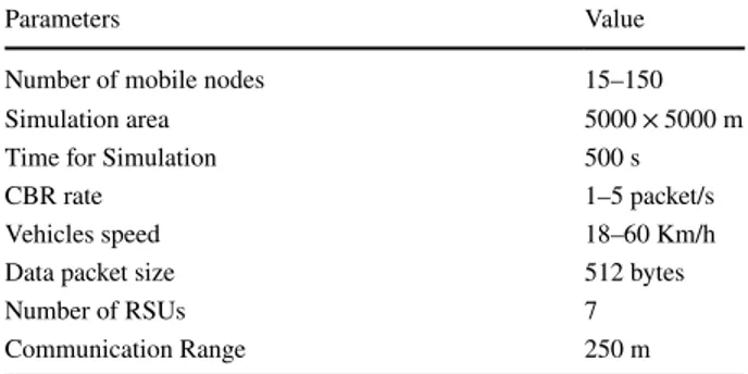
performed using Network simulator 3 (NS3). Using SUMO, vehicular movement file is generated for an area of 5 km2. Standard wireless configurations were used where the communication range for RSU and vehicles were set to 250 m and wireless bandwidth to 5 Mbps, respectively. Table 4 summarized other simulation parameters for our scenario.
5.1 Protocols Compared
We have compared our proposed protocol with ROAMER [9] and TCAR [16] which is identi-cal to IARAR in the way it operates. Compared protocol ROAMER is based on incorporating the approach of carry and forwarding. Every vehicle in ROAMER sends Hello packets to its neighbors periodically. Every vehicle manages a table of the directions, pseudonyms, posi-tions, speeds and time stamps of vehicles in its proximity and the proximity is defined using a proximity threshold which varies from network to network. ROAMER explores the presence of fixed infrastructure using RSUs to forward packets between distant locations in VANETs. However, vehicular network is preferred for sending packets by a vehicle to its proximity. Rout-ing strategy in ROAMER is divided into to parts: (1) routRout-ing from vehicle to RSU, (2) routRout-ing from RSU to vehicle. These actions are identical to those which are used in IARAR except that in IARAR before sending a packet towards the destination, we do not find a fixed route. Relatively, we look for dynamically, at each road segment, the best GN to forward the packet. ROAMER is applicable for massive RSU deployments however IARAR works satisfactory in both sparse and dense environments. In our simulations of ROAMER, we set the number of RSU to five for scenario 1 and 7 for another to make it consistent with IARAR. The second protocol we have compared is IHRAR [17]. An exclusive QoS algorithm for infrastructure-assisted VANETs is proposed by the selection localization strategy between the intersections. IARAR differs from IHRAR in the following ways: IHRAR focuses on neighbor table forma-tion with route discovery. However, IARAR on the other hand also proposes RSU selecforma-tion, a detailed mathematical model for a stable path, path recovery and packet forwarding over that path. A comprehensive mechanism of route request/reply is discussed in IARAR.
5.2 Metrics
5.2.1 Control Routing Overhead
In Figs. 7b and 8b, routing overhead is determined for all the aforementioned protocols. And it is observed that the total control overhead is escalated with the node density and average
Table 4 Simulation setup Parameters Value
Number of mobile nodes 15–150
Simulation area 5000 × 5000 m
Time for Simulation 500 s
CBR rate 1–5 packet/s
Vehicles speed 18–60 Km/h
Data packet size 512 bytes
Number of RSUs 7
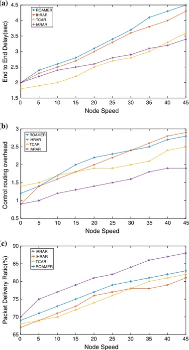
vehicle speed. Figures 7b and 8b shows that routing overhead for IARAR, ROAMER, TCAR and IHRAR increases because of the fact that the redundancy will generate more traffic in highly dense road segments. Routing overhead for IARAR is less when compared with rest of the protocols. This is because of maintaining the road segment level routing table and finding routes outside the road segments only when needed.
5.2.2 Packet Delivery Ratio (PDR)
Packet delivery ratio is the total number of packets received by the destination divided by the total number of packets sent by the source. In this portion, we study the effect of varying average vehicle speed and the number of vehicles on the performance of our proposed proto-col. Figures 7c and 8c describes the outcomes of the PDR for an urban scenario with discrete node density and node speed. Figure 7c shows that IARAR outperforms when compared to ROAMER, TCAR and IHRAR at low as well as at high vehicle density. On the other hand, Fig. 8c shows that the packet delivery for IARAR increases with the increase in speed. The reason is that due the escalation of speed, source vehicle will find the neighbors rapidly while having more chances to deliver the data to neighbor vehicles with high PDR.
5.2.3 End‑to‑End Delay
In case of End-to-End delay, ROAMER operates with poor performance in contrast with IARAR and IHRAR in both the scenarios. This is because paths are calculated and maintained re-actively inside a road segment and towards the RSU. Which benefits in the successful trans-mission of data packets quickly. On the other hand, with the increase in average vehicle speed, ROAMER and TCAR shows more end-to-end delay when compare to the IARAR and IHRAR , as shown in Figs. 7a and 8a. However, IARAR shows very small delay when the average vehi-cle speed varies from 18 to 60 Km/h.
5.2.4 Road Segment Vicinity
In this section, we observed the behavior of IARAR with the change of road segment vicinity ( RVic ). RVic varies from 100 to 1000 m in Gangnam city map, as show in Fig. 6. These values shows extremes of RVic in map which we have used for the simulations. Figure 9 represents
Fig. 6 Gangnam street grid layout
0 50 100 150 Node Density 1 2 3 4 5 6 7
End to End delay(sec)
ROAMER IHRAR TCAR IARAR (a) 0 50 100 150 Node Density 1.5 2 2.5 3 3.5 4 4.5
Control routing overhead
ROAMER IHRAR TCAR IARAR (b) 0 50 100 150 Node Density 40 50 60 70 80 90
Packet Delivery Ratio(%)
ROAMER IHRAR TCAR IARAR
(c)
Fig. 7 IARAR, IHRAR, TCAR and ROAMER: End-to-End delay (a), Control routing overhead (b), Packet delivery ratio (c) versus node density
that delivery ratio of IARAR increases as the area increases from 200 to 700 m and steady value is achieved after some decay. However, average node traffic and packet delay increases to attain an approximate constant value.
Node Speed 1.5 2 2.5 3 3.5 4 4.5
End to End Delay(sec)
ROAMER IHRAR TCAR IARAR (a) 0 5 10 15 20 25 30 35 40 45 Node Speed 0.5 0 5 10 15 20 25 30 35 40 45 1 1.5 2 2.5 3
Control routing overhead
ROAMER IHRAR TCAR IARAR (b) (c) Node Speed 65 70 75 80 85 90
Packet Delivery Ratio(%)
IARAR IHRAR TCAR ROAMER
0 5 10 15 20 25 30 35 40 45
Fig. 8 IARAR, IHRAR, TCAR and ROAMER: End-to-End delay (a), Control routing overhead (b), Packet delivery ratio (c) versus node speed (Km/h)
6 Conclusion
In this paper, we have suggested a new road-aware routing scheme for Internet of Vehi-cles with the estimation of path duration. Like other routing strategies, IARAR does not require the specialized distribution of RSUs. With the proper selection of RSU, our pro-posed mechanism selects the durable route with consideration the following important parameters: hop cont, direction of movement and vehicle velocity. In IARAR, roads are divided into road segments and each road segment contains GNs for inter-segment com-munication. Route discovery process can be initiate by only using GNs, hence there is no need to flood the network with control packets. The performance of IARAR proto-col is evaluated by comprehensive simulations using SUMO and NS3 simulator. IARAR shows promising results in terms of end-to-end delay and packet overhead in compari-son with IHRAR, TCAR and ROAMER. IARAR investigates one of the key problems in
Fig. 9 Average vehicle traffic, delivery ratio and delay of IARAR for different length of road segments using map as shown in Fig. 6 3 3.5 4 4.5 5 5.5 6 6.5 0 200 400 600 800 1000 Av g Ve hicle tr affi c (Kb/ secl Road segment (m) (a) 0.4 0.45 0.5 0.55 0.6 0.65 0.7 0.75 0.8 0 200 400 600 800 1000 Deliv ery Ra o Road segment (m) (b) 4 4.5 5 5.5 6 6.5 7 0 200 400 600 800 1000 Pa ck et Del ay (Sec) Road segment (m) (c)
by exploring the technique of hybrid routing (road-aware routing) and selecting a stable route can significantly improve the routing performance of IoV.
Acknowledgements This research was supported by Basic Science Research Program through the National Research Foundation of Korea (NRF) funded by the Ministry of Education (NRF-2016R1D1A1B01016322). This research was supported by the 2019 scientific promotion program funded by Jeju National University.
Open Access This article is distributed under the terms of the Creative Commons Attribution 4.0 Interna-tional License (http://creat iveco mmons .org/licen ses/by/4.0/), which permits unrestricted use, distribution, and reproduction in any medium, provided you give appropriate credit to the original author(s) and the source, provide a link to the Creative Commons license, and indicate if changes were made.
References
1. Yang, X., Li, M., Qian, Z., & Di, T. (2018). Improvement of gpsr protocol in vehicular ad hoc net-work. IEEE Access, 6, 39515–39524.
2. Alsharif, N., Céspedes, S., & Shen, X. S. (2013). ICAR: Intersection-based connectivity aware routing in vehicular ad hoc networks. In 2013 IEEE International conference on communications
(ICC) (pp. 1736–1741).
3. Alsharif, N., & Shen, X. (2017). i CAR-II: Infrastructure-based connectivity aware routing in vehicular networks. IEEE Transactions on Vehicular Technology, 66(5), 4231–4244.
4. Karagiannis, G., Altintas, O., Ekici, E., Heijenk, G., Jarupan, B., Lin, K., et al. (2011). Vehicular networking: A survey and tutorial on requirements, architectures, challenges, standards and solu-tions. IEEE Communications Surveys and Tutorials, 13(4), 584–616.
5. Azimifar, M., Todd, T. D., Khezrian, A., & Karakostas, G. (2016). Vehicle-to-vehicle forwarding in green roadside infrastructure. IEEE Transactions on Vehicular Technology, 65(2), 780–795. 6. Bai, F., Elbatt, T., Hollan, G., Krishnan, H., & Sadekar, V. (2006). Towards characterizing and
classifying communication-based automotive applications from a wireless networking perspective. In Proceedings of IEEE workshop on automotive networking and applications (AutoNet), San Fran-cisco, CA, USA (pp. 1–25).
7. Borsetti, D., & Gozálvez, J. (2010). Infrastructure-assisted geo-routing for cooperative vehicular networks. In 2010 IEEE vehicular networking conference (pp. 255–262).
8. Sheu, J.-P., Lo, C.-Y., & Hu, W.-K. (2011). A distributed routing protocol and handover schemes in hybrid vehicular ad hoc networks. In 2011 IEEE 17th International conference on parallel and
distributed systems (pp. 428–435).
9. Mershad, K., Artail, H., & Gerla, M. (2012). Roamer: Roadside units as message routers in vanets.
Ad Hoc Networks, 10(3), 479–496.
10. Sheu, J.-P., Hu, W.-K., & Bol, R. E. (2012) A registration system for aiding in localization and routing in hybrid vanets. In 2012 12th IEEE International conference on ITS telecommunications (pp. 694–699).
11. Yan, G., & Olariu, S. (2011). A probabilistic analysis of link duration in vehicular ad hoc networks.
IEEE Transactions on Intelligent Transportation Systems, 12(4), 1227–1236.
12. Raw, R., Toor, V., & Singh, N. (2012). Path duration analysis in vehicular ad hoc network.
Interna-tional Journal of AdHoc Network System, 2(4), 57–66.
13. Yasser, A., Zorkany, M., & Abdel Kader, N. (2017). Vanet routing protocol for v2v implementation: A suitable solution for developing countries. Cogent Engineering, 4(1), 1362802.
14. Al-Rabayah, M., & Malaney, R. (2012). A new scalable hybrid routing protocol for vanets. IEEE
Transactions on Vehicular Technology, 61(6), 2625–2635.
15. Venkatramana, D. K. N., Srikantaiah, S. B., & Moodabidri, J. (2018). Cisrp: Connectivity-aware intersection-based shortest path routing protocol for vanets in urban environments. IET Networks, 7(3), 152–161.
16. Qin, H., & Yu, C. (2017) A road network connectivity aware routing protocol for vehicular ad hoc networks. In 2017 IEEE International conference on vehicular electronics and safety (ICVES) (pp. 57–62).
17. Abbas, M. T., & Song, W.-C. (2017) Infrastructure-assisted hybrid road-aware routing and qos pro-visioning in vanets. In 2017 19th Asia–Pacific network operations and management symposium
(APNOMS) (pp. 370–373).
18. Bai, F., Sadagopan, N., Krishnamachari, B., & Helmy, A. (2004). Modeling path duration distributions in manets and their impact on reactive routing protocols. IEEE Journal on Selected Areas in
Communi-cations, 22(7), 1357–1373.
19. Lim, G., Shin, K., Lee, S., Yoon, H., & Ma, J. (2007). Link stability and route lifetime in ad-hoc net-works. EURASIP Journal on Wireless Communications and Networking, pp. 1–6
20. Sadagopan, N., Bai, F., Krishnamachari, B., & Helmy, A. (2003). Paths: analysis of path duration sta-tistics and their impact on reactive manet routing protocols. In Proceedings of the 4th ACM
interna-tional symposium on mobile ad hoc networking and computing (pp. 245–256).
21. De, S., Caruso, A., Chaira, T., & Chessa, S. (2006). Bounds on hop distance in greedy routing approach in wireless ad hoc networks. IJWMC, 1(2), 131–140.
22. Cheng, Z., & Heinzelman, W. B. (2004) Exploring long lifetime routing (llr) in ad hoc networks. In
Proceedings of the 7th ACM international symposium on Modeling, analysis and simulation of wire-less and mobile systems. (pp. 203–210).
23. Joa-Ng, M., & Lu, I.-T. (1999). A peer-to-peer zone-based two-level link state routing for mobile ad hoc networks. IEEE Journal on selected areas in communications, 17(8), 1415–1425.
24. Papoulis, A., & Pillai, S. U. (2002). Probability, random variables, and stochastic processes. New York: Tata McGraw-Hill Education.
Publisher’s Note Springer Nature remains neutral with regard to jurisdictional claims in published maps and institutional affiliations.
Muhammad Tahir Abbas started working as a PhD student at the Department of Computer Science, Karlstad University on February 1st 2019. Muhammad Tahir holds a Master’s degree in Computer Engi-neering (2018) from Jeju National University, South Korea, and BE degree in Computer Engineering (2015) from NUST, Pakistan, with research focuses on 5G, VANETs, SDN & NFV. He worked as a Research Assistant at Center for Advanced Research in Engineering (C@RE) from 2015-2016. His current research includes Energy Man-agement in Narrowband Internet of Things(NB-IoT).
Afaq Muhammad received PhD degree in Computer Engineering from Jeju National University, MS degree in Electrical Engineering with emphasis on Telecom from Blekinge Institute of Technology, Sweden, and BS degree in Electrical Engineering from University of Eng. and Technology, Peshawar, Pakistan in 2017, 2010, and 2007 respectively. Currently, he is working as an Assistant Professor in the Department of Computer Science and IT at Sarhad University of Science and IT, Pakistan. He also worked as a Postdoctoral Researcher at Network Convergence Lab, Jeju National University. Before starting his PhD, he worked as a Research Associate in the Faculty of Computer Science and Engineering at GIK institute of Engineering Sciences and Tech-nology, Pakistan, and as a Lecturer in the Department of Electrical Engineering at City University of Science and IT. His research inter-ests are cloud computing, software defined networking, network func-tion virtualizafunc-tion, wireless networks, and protocols, machine learning, and data science.
Wang‑Cheol Song received B.S. degree in Food Engineering and Elec-tronics from Yonsei University, Seoul, Korea in 1986 and 1989, respectively. And M.S. and Ph.D. in Electronics studies from Yonsei University, Seoul, Korea, in 1991 and 1995, respectively. Since 1996 he has been working at Jeju National University. His research interests include VANETs and MANETs, Software Defined Networks, network security, and network management.