Research
FEM analysis of the mechanical
integrity for the canister intended
for storage of spent nuclear fuel with
regard to copper creep ductility
2017:18
SSM perspective Background
For final storage of spent nuclear fuel it is suggested by the Swedish nuclear fuel and waste management company (SKB) to emplace the nuclear fuel into copper canisters which are surrounded by bentonite clay at approximately 500 meters’ depth into granitic rock. After emplacement of the canisters Bentonite swelling due to water satura-tion and hydrostatic pressure build up the canisters will be subjected to compressive loads. The canisters are constructed with a load carrying cast insert of ductile iron which is surrounded by a 50 mm thick corro-sion resistant copper shell. The copper shell is not in itself load carry-ing but must retain its corrosion barrier ability (i.e thickness) when the compressive load is applied very slowly. For materials where the load is applied slowly, materials creep properties become of vital importance. It has been shown that creep ductility for oxygen free copper can be very low (< 1 %). SKB has for this reason proposed to use oxygen free copper alloyed with small amounts of phosphorous (30<P<100 ppm) in order to ensure that creep ductility is higher than 15 %. In order to verify the copper materials creep ductility, extensive creep testing has been performed by SKB. However, the challenge is to extrapolate test results lasting in a yearly scale into time scales lasting for several 10000 years, which is necessary to assess the repository long-term safety. Instead of performing creep tests, an alternative verification approach has been suggested to instead determine the minimum creep ductility needed to maintain sufficient safety margins for the canisters copper shell.
Objectives
The objective of this work is to study an alternative approach to deter-mine the minimum creep ductility needed to ensure the thickness of the canisters corrosion barrier.
Results
In this report, two different kinds of finite element analysis have been conducted simulating copper canister deformation during buffer satura-tion and hydrostatic pressure build up. Instead of using a creep model for material behaviour, an alternative approach using an elastic-plastic material model has been applied in this work.
Results from the finite element analysis of strain levels in the area between the copper lid and copper tube show similar strain behav-iour as earlier reported by SKB, using a time dependent material creep model. This result was expected since the strain level in this area primar-ily is deformation controlled in this load case. However, one benefit of using the alternative approach in this work is to study how different geo-metric parameters as well as how other material properties like friction, change the strain levels. The alternative approach can thus be one tool in optimizing the canister geometry in order to minimize copper strain. In the second part of the report the aim was to study the containment
function of the copper shell is to provide an approximately 50 mm thick corrosion barrier towards the oxygen free saline groundwater surround-ing the canister after emplacement. Creep brittleness of the copper shell can potentially decrease the corrosion barrier by formation of creep cracks. The influence of creep brittleness was in this investigation stud-ied by application of a damage mechanics approach based on defining a criterion for maximum allowable plastic strain. When the criterion is reached damage is initiated and the load bearing capacity is reduced to zero. The analysis involved a number of material parameters which were not known for the copper material in question. For this reason, some of the unknown material parameters were varied in order to investi-gate the method and get an idea of how the copper canister behaves under different assumptions. More knowledge about the actual mate-rial behaviour would be needed to be able to better evaluate the results. With these short-comings in mind, results from the damage mechanics analysis indicates that the minimum creep ductility for the copper mate-rial used for the canister should be in the order of 10% to withstand the pressure load. One attempt to use the damage mechanics approach for a load controlled case (internal pressure) was conducted, with limited suc-cess. It is suggested that a fracture mechanics approach might be more appropriate for analyzing such a load case. In summary, this study has shown that damage mechanics analyses are sensitive to several material parameters which are a necessary input in the analysis. More knowledge regarding the material properties are needed before accurate predic-tions using this method can be made. However, based on the damage evolution shown in this report for creep brittle copper, it can be con-cluded that creep brittleness of copper can potentially induce concen-trated damage in certain directions meaning that the corrosion barrier of the copper shell can be reduced.
Need for further research
Based on the results in this investigation it is found that more work with regard to creep deformation should be conducted to consider unfavorable geometric conditions, i.e. large gaps due to disadvantageous manufacturing tolerance outcomes as well as eccentric location of the insert inside the copper canister. Additionally, friction between copper-copper and copper-copper-ductile iron should be considered in these analyses. For deformation controlled load cases the applied damage mechanics approach can be used as a tool to assess the minimum creep ductility needed for the copper material. However, to make a thorough analysis further knowledge and in some case determination of actual material properties is needed. To derive load controlled cases of canisters copper shell, other methods to derive damage evolution are needed to be developed.
Project information
Contact person SSM: Jan Linder Reference: SSM2016-3899
2017:18
Author: Calle Engman
FS Dynamics Sweden AB, Göteborg
FEM analysis of the mechanical
integrity for the canister intended
for storage of spent nuclear fuel with
regard to copper creep ductility
This report concerns a study which has been conducted for the Swedish Radiation Safety Authority, SSM. The conclusions and view-points presented in the report are those of the author/authors and
Summary
SKB:s post closure safety analysis of copper canisters in repository environments have been reviewed by SSM, with respect to the creep model used for the OFP copper and its implementation into FE-analysis. The review identified a couple of issues in need of further investigation and the purpose of this work is to provide an independent analysis regarding these.
Sensitivity to geometric factors are investigated, in particular effects of an eccentric location of the insert inside the copper canister and effects of larger gaps resulting from manufacturing tolerances. A method for assessing minimum required copper creep ductility using damage mechanics is studied.
Cases analysed with large gaps due to geometric tolerances and eccentric location result in significantly increased strains, showing that the geometry is important. Friction is also a relevant factor which, in combination with geometric factors, influence the deformation behavior and resulting strains. It is recommended that creep analyses are updated to consider the worst case regarding geometry and friction.
Damage mechanics analysis is performed for a few cases with different strain criteria and postulated material behavior. Results show a required creep ductility in the range of 1% to 10%. It is concluded that the method used for this analysis is quite sensitive to several parameters related to material properties as well as the numerical solution. More
knowledge regarding the actual material properties would be needed to make more accurate predictions regarding required creep ductility.
Sammanfattning
SKB:s säkerhetsanalys av kopparkapslar för slutförvar av radioaktivt avfall har granskats av SSM, med avseende på krypmodell och implementering av denna i FE-analys. Granskningen påvisade några brister i SKB:s analyser och syftet med föreliggande rapport är att utgöra en oberoende analys med avseende på dessa.
Känslighet mot variationer i geometriska faktorer analyseras, specifikt effekterna av excentrisk placering av gjutjärnsinsatsen inuti kopparkapseln samt effekterna av större glapp mellan de olika delarna resulterande av tillverkningstoleranser. Vidare undersöks en metod för att utvärdera minsta nödvändiga nivå på krypduktilitet.
Analys av toleransutfall med stora glapp samt excentrisk placering visar att detta leder till signifikant högre töjningar i kopparkapseln, vilket visar att geometrin är viktig. Friktion visas också vara en relevant faktor vilken i kombination med geometriska faktorer påverkar deformationsbeteende och resulterande töjningar. Det rekommenderas att krypanalyser uppdateras för att ta hänsyn till konservativa utfall med avseende på geometri/toleranser samt friktion.
Skademekaniska analyser utförs med ett antal olika postulerade fall med varierande töjningskriterier samt materialbeteende. Resultaten visar en minsta nödvändiga nivå på krypduktilitet mellan 1% och 10%. Metoden som används för dessa analyser är känslig med avseende på ett antal parametrar relaterade till såväl materialegenskaper som den numeriska lösningen. Mer detaljerad kunskap om de faktiska materialegenskaperna skulle behövas för att göra en mer noggrann bedömning av minsta nödvändiga krypduktilitet.
Content
1. Introduction ... 2
1.1. Background ... 2
1.2. Purpose ... 2
1.3. Analysis approach ... 2
2. Prerequisites for the FE-analysis ... 4
2.1. Geometry ... 4
2.2. Material ... 5
2.3. Loads and boundary conditions ... 5
3. Analysis methodology ... 7
3.1. FE-model ... 7
3.2. Elastic-plastic analysis ... 7
3.3. Damage mechanics analysis ... 8
4. Elastic-plastic analysis ... 11
4.1. Comparison with creep analysis ... 11
4.2. Investigation of geometric effects ... 13
4.3. Friction effects ... 15
4.4. Internal pressure case ... 16
5. Damage mechanics analysis ... 17
5.1. Damage analysis 1 ... 18
5.2. Damage analysis 2 ... 19
5.3. Internal pressure case ... 20
6. Discussion ... 21
6.1. Elastic plastic analysis ... 21
6.2. Damage mechanics analysis ... 21
7. Conclusions ... 24
8. Future work ... 25
References ... 26
Appendix A ... 27
A.1. Results – Investigation of geometric effects ... 28
A.2. Results – Friction effects ... 32
A.3. Results – Damage mechanics analysis 1 ... 34
A.4. Results – Damage mechanics analysis 2 ... 37
1. Introduction
1.1. Background
SKB:s post closure safety analysis of copper canisters in repository environments have been reviewed by SSM in [1], with respect to the creep model used for the OFP copper and its implementation into FE-analysis in [2].
The review identified a couple of issues in need of further investigation, of which the following are of relevance to the work in this report:
- A concentric location of the insert with respect to the copper cylinder is assumed in SKB’s analyses. In practice an eccentric location can be expected as a result of handling during the emplacement process. Furthermore the manufacturing tolerances may result in a larger axial gap between the insert and the copper lid. - A minimum required copper creep ductility for the different load scenarios
should be determined in order to give confidence to the structural verification of the copper canister. A damage mechanics approach is suggested as a way of looking at this.
1.2. Purpose
The purpose of this work is to provide an independent analysis regarding the issues identified in [1]. An alternative approach is used, excluding creep properties and instead focusing on exploring effects of different parameters, in order to provide value in addition to previous analyses.
Sensitivity to geometric factors shall be investigated, in particular effects of an eccentric location of the insert inside the copper canister and effects of larger gaps resulting from manufacturing tolerances.
A method for assessing minimum required copper creep ductility using damage mechanics shall be studied.
1.3. Analysis approach
The defined purpose is approached by two sets of analyses. Firstly an elastic-plastic analysis is performed, without creep properties, which is used to investigate geometric factors and identify a worst case regarding tolerances and eccentricity. Secondly a damage mechanics approach is studied in order to investigate required ductility. The objectives of the analyses can be summarized as follows.
Elastic-plastic analysis:
- Investigate effects of disadvantageous manufacturing tolerance outcome - Investigate effects of eccentric location of the insert inside the copper canister - Investigate the influence of friction in copper-copper contact areas
Damage mechanics analysis:
- Define a method for analysis
- Identify relevant parameters and issues - Analyse effects of different strain criteria
2. Prerequisites for the FE-analysis
2.1. Geometry
The design of the copper canister is presented in [3]. Figure 2-1 shows a schematic view of the canister, insert and copper lid. Dimensions and tolerances are specified in [3].
Figure 2-1: Canister and insert geometry [3]
A weld root defect in the copper lid to cylinder weld were postulated and included in the analyses in [2]. The defect has the shape of a 3 mm radial slit extending outwards from the axial gap between the lid and the cylinder. This is included in the same way in the present analyses, see Figure 2-2.
Figure 2-2: Geometry in the area around the weld between copper lid and cylinder
All dimensions are subject to manufacturing tolerances, specified in Table 3-3 through Table3-6 in [3], which have an effect on the size of the gaps between the insert, the copper cylinder and the copper lid. The parameters varied in the analysis are presented in section 4.2.
Copper lid
Copper cylinder
Weld root defect Weld
2.2. Material
The canister is made of oxygen free phosphorus-alloyed (OFP) copper and the insert is made of cast iron with a steel lid. Material properties are taken from SKB:s reports [4] and [5].
The stress-strain curve for OFP Copper is specified by equation (17) in [4], with
parameters specified for multiple temperatures and strain rates. The values corresponding to 20°C and a strain rate of 10-7 s-1 are used here. No rate dependent properties (creep) are
to be included in the present analysis, hence using the values tabulated for the lowest strain rate.
The stress-strain curves for cast iron and steel are taken from those tabulated in [5]. Linear properties are listed in Table 2-1. Stress-strain curves fort the three materials are shown in Figure 2-3.
Table 2-1: Linear material properties
Copper Cast Iron Steel
Young’s modulus [GPa] 120 166 210
Poisson’s ratio [-] 0.308 0.32 0.30
Density [kg/m3] 8940 7200 7850
Figure 2-3: True stress vs true plastic strain for the materials used in the analyses.
2.3. Loads and boundary conditions
Several load evolution scenarios are analysed in [2], with temperatures and external pressures developing as shown in Figure 2-4.
0 100 200 300 400 500 600 0,000 0,100 0,200 0,300 0,400 0,500 Str ess [M Pa] Plastic strain [-]
True stress vs plastic strain
Copper Cast iron Steel
Figure 2-4: Pressure and temperature development from [2]
Since no time dependent factors are included in the present analysis these scenarios can be simplified to two static cases, representing the highest internal and external pressure respectively.
- External pressure: 60 MPa (glacial load)
- Internal pressure: 0.5 MPa (internal gas pressure effects) Thermal effects are neglected in this report.
Two sets of boundary conditions are analysed in [2], shown in Figure 2-5, where the canister rests on the central part of the bottom lid or the outer edge of the bottom lid. The latter is concluded in [2] to represent the worst case for the top lid area and is therefore used in the present analyses.
Figure 2-5: Two different cases of boundary conditions at the bottom of the canister from [2]. The
3. Analysis methodology
3.1. FE-model
Calculations are performed using the finite element solver Abaqus [6]. Geometry and mesh is created in the preprocessing software Ansa [7].
An axisymmetric approach is used in the calculations. The cast iron insert is modeled as completely solid, i.e. excluding the steel pipes inside. The eccentric location of the insert postulated for the present analysis will result in a larger radial gap on one side, allowing for larger deformations/strains locally. This larger gap is approximated by reducing the radius of the insert correspondingly.
The mesh consists of roughly 40 000 elements. 4-noded axisymmetric quad elements with reduced integration (CAX4R in Abaqus [6]) are used. The area surrounding the interface between the copper lid and cylinder, where large deformations are expected, have a refined mesh size.
Surface to surface contacts with finite sliding are implemented between the insert and the canister, as well as between the different canister parts. Friction is set to 0.1 in the general case but is also one of the parameters studied, see section 4.3.
The analyses are performed using static conditions in Abaqus Standard (implicit solver). Nonlinear geometric effects are included.
The model is shown in Figure 3-6.
Figure 3-6: FE-model mesh
3.2. Elastic-plastic analysis
Elastic-plastic analysis is performed using isotropic hardening defined by the stress-strain curves described in section 2.2. No creep effects are included.
- Comparison with creep analysis in [2]
- Geometric factors, i.e. size of gaps, eccentricities - Effects of friction on deformations
3.3. Damage mechanics analysis
A damage mechanics approach is studied in order to investigate required creep ductility. No creep effects are included and the approach is instead based on defining a criterion for maximum allowable plastic strain. When the criterion is reached damage is initiated and the load bearing capacity is reduced to zero, representing the situation where the material is fully creep damaged.
Different strain criteria are investigated, aiming to investigate whether a level of strain can be found where the copper cylinder stays leakage tight. The purpose is not to provide a proper verification of the structural integrity, but to give an idea of the required creep ductility.
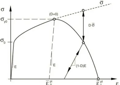
Analysis is performed using Abaqus built in functions for damage initiation and damage evolution for ductile materials. Figure 3-7 shows the basic principle of the stress-strain behaviour. The analyses are performed using static conditions in Abaqus implicit solver, where the load is ramped up in small increments and equilibrium is enforced in each step. Evaluation of damage criteria and adjustment of the stiffness matrix due to damage evolution is also performed in each step. The size of the increments are adjusted automatically by the solver.
Figure 3-7: Stress-strain curve with progressive damage degradation
The elastic-plastic curve is the same as described in section 3.2. The damage initiation criterion is defined as a level of equivalent plastic strain, denoted 𝜀𝜀̅𝑜𝑜𝑝𝑝𝑝𝑝 in the figure.
Equivalent plastic strain is defined as 𝜀𝜀̅𝑝𝑝𝑝𝑝 = ∫ 𝜀𝜀̅̇𝑡𝑡 𝑝𝑝𝑝𝑝𝑑𝑑𝑑𝑑
0
𝜀𝜀̅̇𝑝𝑝𝑝𝑝 = √2 3𝜀𝜀̇𝑖𝑖𝑖𝑖
𝑝𝑝𝑝𝑝𝜀𝜀̇ 𝑖𝑖𝑖𝑖𝑝𝑝𝑝𝑝
After damage is initiated the stiffness is reduced by the factor D, which is controlled by the defined damage evolution law in relation to the undamaged stress 𝜎𝜎̅, i.e.
𝜎𝜎 = (1 − 𝐷𝐷)𝜎𝜎̅ .
The equivalent plastic strain used for the damage initiation criterion may be defined as a function of stress triaxiality. The stress triaxiality basically describes if the state of stress is dominated by tensile or compressive stress, and this is used in one of the analysis cases to investigate how the behaviour is affected if it is postulated that cracks are driven by tensile stresses only (see section 5.2).
The stress triaxiality factor, 𝜂𝜂, is defined as 𝜂𝜂 = −𝑝𝑝/𝑞𝑞
where 𝑝𝑝 is the pressure stress and 𝑞𝑞 is the Mises equivalent stress, defined as 𝑝𝑝 = −13𝜎𝜎𝑖𝑖𝑖𝑖
𝑞𝑞 = √32𝑆𝑆𝑖𝑖𝑖𝑖𝑆𝑆𝑖𝑖𝑖𝑖
where 𝑆𝑆 is the deviatoric stress tensor 𝑆𝑆𝑖𝑖𝑖𝑖= 𝜎𝜎𝑖𝑖𝑖𝑖+ 𝑝𝑝𝛿𝛿𝑖𝑖𝑖𝑖
The sign of the stress triaxiality factor is dependent on the hydrostatic stress components, and is positive for a tension dominated state of stress and negative for a compression dominated state of stress. It shall be noted that the damage initiation is still based on the equivalent plastic strain, i.e. all strain components contribute, but the criterion can be set to different values for different levels of triaxiality. The way this is used in the mentioned analysis case is to set a very high strain criterion when the triaxiality factor is negative, resulting in no damage initiation in elements subject to compression and unaffected damage behaviour for those subject to tension.
The value of the equivalent plastic strain at failure, 𝜀𝜀̅𝑓𝑓𝑝𝑝𝑝𝑝, depends on the characteristic length of the element and is not used to specify the damage evolution law. Instead, the damage evolution law is specified in terms of equivalent plastic displacement, 𝑢𝑢̅𝑝𝑝𝑝𝑝, or in
terms of fracture energy dissipation, 𝐺𝐺𝑓𝑓, which are related as
𝐺𝐺𝑓𝑓 = ∫ 𝐿𝐿𝜎𝜎𝜀𝜀̅𝑓𝑓 𝑦𝑦𝑑𝑑𝜀𝜀̅𝑝𝑝𝑝𝑝
𝑝𝑝𝑝𝑝
𝜀𝜀̅0𝑝𝑝𝑝𝑝 = ∫ 𝜎𝜎𝑦𝑦𝑑𝑑𝑢𝑢̅𝑝𝑝𝑝𝑝 𝑢𝑢̅𝑓𝑓𝑝𝑝𝑝𝑝
0
where 𝜎𝜎𝑦𝑦 is the yield stress and the characteristic length of the element, 𝐿𝐿, defined as the
length of a line across an element for a first-order element, is taken into account in order to make the function relatively mesh independent. The increment of the equivalent plastic displacement is
𝑢𝑢̅̇𝑝𝑝𝑝𝑝= 𝐿𝐿𝜀𝜀̅̇𝑝𝑝𝑝𝑝
The damage function is specified as a linear function in the present analyses, giving the damage increment
𝐷𝐷̇ =𝑢𝑢̅̇𝑝𝑝𝑝𝑝
𝑢𝑢̅𝑓𝑓𝑝𝑝𝑝𝑝
where 𝑢𝑢̅𝑓𝑓𝑝𝑝𝑝𝑝 is the equivalent plastic displacement at the point of failure.
When the element is fully damaged, i.e. 𝐷𝐷 = 1 and remaining stiffness is zero, the element is either removed completely or remains in the model. In the latter case it provides only a very small stiffness (1%) and furthermore the bulk stiffness in compression is not degraded (corresponding to a fluid-like behaviour). The deviatoric stresses, 𝑆𝑆, and the pressure stresses, 𝑝𝑝 (defined above) are calculated as
𝑆𝑆 = (1 − 𝐷𝐷𝑑𝑑𝑑𝑑𝑑𝑑)𝑆𝑆̅
𝑝𝑝 = (1 − 𝐷𝐷𝑑𝑑𝑣𝑣𝑝𝑝)𝑝𝑝̅
where 𝑆𝑆̅ and 𝑝𝑝̅ are the undamaged deviatoric and pressure stresses, and the deviatoric and volumetric parts of the stiffness reduction factor 𝐷𝐷 are
𝐷𝐷𝑑𝑑𝑑𝑑𝑑𝑑= 𝐷𝐷
𝐷𝐷𝑑𝑑𝑣𝑣𝑝𝑝= {𝐷𝐷 𝑖𝑖𝑖𝑖 𝑝𝑝̅ ≤ 00 𝑖𝑖𝑖𝑖 𝑝𝑝̅ > 0
The analysis of degrading material is computationally difficult. To somewhat alleviate the convergence problems a viscous regularization scheme is used, which causes the tangent stiffness matrix of the softening material to be positive for sufficiently small time increments. The viscosity parameter basically introduces some artificial numerical stabilization which has some effects on the solution and should therefore be set as low as possible to get accurate results, but due to the trade-off with numerical convergence it will be chosen iteratively.
None of the material parameters mentioned are known for the material in question. Instead some of the parameters are varied in order to investigate the method and get an idea of how the copper canister behaves under different assumptions.
4. Elastic-plastic analysis
The external pressure load case is analysed, using elastic-plastic analysis as described in section 3.1 and 3.2, in the following sections:
- 4.1. Comparison with creep analysis - 4.2. Investigation of geometric effects - 4.3. Friction effects
The internal pressure case is analysed in section 4.4. The parameters regarding geometry, friction, etc. are not of relevance to this load case.
4.1. Comparison with creep analysis
The results from elastic-plastic analysis of the external pressure load case is compared to the creep analysis results from [2]. The results reported in [2] are primarily creep strains, denominated in Abaqus as CEEQ, which actually include all inelastic strains (see section 10 in [2]). This means there is no way of separating the creep effects from ordinary plastic strain, apart from looking at time histories.
The comparison is made between equivalent plastic strain, PEEQ, in the case of the present analyses and creep strains, CEEQ, in the case of the creep analyses from [2]. Furthermore max and min principal stresses are compared.
The case analysed have nominal geometry and gaps (case A in section 4.2) and a friction coefficient of 0.1. The external pressure load is 60 MPa, i.e. corresponding to the last step in the analysis from [2].
Figure 4-8 through Figure 4-10 show strains and stresses from the two analyses. Note that the figures show the top lid area (corresponding to the area shown in Figure 3-6) with the canister rotated 90° to a horizontal orientation in these plots.
Figure 4-8: Equivalent creep strain, CEEQ, from [2] (left) compared to equivalent plastic strain,
Figure 4-9: Max principal stress from [2] (left) compared to elastic-plastic analysis (right). Contour
scale in elastic-plastic analysis is adjusted to match.
Figure 4-10: Min principal stress from [2] (left) compared to elastic-plastic analysis (right). Contour
scale in elastic-plastic analysis is adjusted to match.
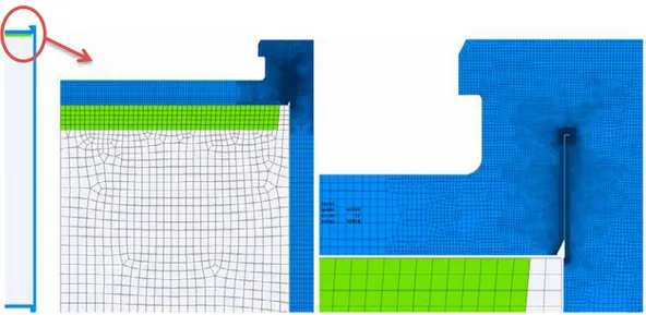
It can be seen the general pattern of strain is very similar, while the stress fields are more different. There is however a big difference in mesh size, meaning it is not possible to compare local effects. An example of the local effects and the mesh difference can be seen in Figure 4-11.
Figure 4-11: Detailed view showing effects of the mesh difference on local results between [2] (left)
The strains are primarily deformation controlled in this load case, since the external pressure is large enough to make closing of the gaps the limiting factor. This is probably the reason the inelastic strains are so similar, whether resulting from creep or ordinary plastic deformation.
4.2. Investigation of geometric effects
The gaps between the insert and copper canister can vary depending on manufacturing tolerances and eccentric location of insert and/or the copper lid. This will have an effect on the results from the external pressure load case, since the gaps limit the deformation and hence also the strains.
Three gaps are identified, shown in Figure 4-12:
- Gap 1: the axial gap between copper lid and the steel lid of the insert - Gap 2: the radial gap between the insert and the copper cylinder - Gap 3: the radial gap between the copper lid and the cylinder
Figure 4-12: Gaps affected by manufacturing tolerances and eccentricities
Three cases are compared to evaluate the effects of gaps resulting from manufacturing tolerances and eccentric location. These are:
- A: nominal geometry, concentric (corresponding to the model in [2]) - B: maximum gaps, concentric
- C: maximum gaps, eccentric location of both insert and copper lid (in the same direction)
The size of the gaps in each case are listed in Table 4-2.
Table 4-2: Gap distances for the geometric cases analysed
Case Gap 1 [mm] Gap 2 [mm] Gap 3 [mm]
A 2.00 1.50 0.30
B 3.10 1.75 0.30
Resulting equivalent plastic strains in the area around the upper lid weld are shown in Figure 4-13. It can be seen that the case with the largest gaps have significantly larger areas of high strain.
Figure 4-13: Equivalent plastic strains for geometric cases A, B and C. Contour limit is set to 5% in
all three cases
It can be seen that the size of the gaps have a rather large effect on the size of the high strain areas. Larger gaps are clearly worse when it comes to both absolute strain levels and size of affected areas. Since the external pressure load is so large the contacts are the only limiting factor for deformations.
Several plots showing these results in more detail are included in Appendix A.1.
Case C is clearly the most severe case, and will be used in the damage mechanics analysis in section 5. Equivalent strain results for this case with the contour scale set to 10%, 1% and 0.1% respectively (corresponding to the strain damage criteria to be analysed) is shown in Figure 4-14.
4.3. Friction effects
Since there is a sliding movement between the copper cylinder and the copper lid the friction coefficient could have an effect on the resulting deformations. The actual value of friction is probably around 1.0 for copper-copper contact (static, dry conditions). A sensitivity study is performed, comparing three different values of the friction coefficient, 𝜇𝜇 = 0, 0.1 and 0.5, where 0.5 is concluded to be high enough to prevent sliding. The creep analyses in [2] use a friction coefficient of 0.1.
The analyses are based on geometric case C, i.e. maximum gaps and eccentric location of both insert and copper lid.
Figure 4-15 shows that the case with 𝜇𝜇 = 0.5 result in a different behavior, where the contact surface between copper cylinder and copper lid sticks and limits the axial movement of the copper lid. The maximum slipping distance in this contact is 2.00, 1.57 and 0.06 mm for the three cases respectively and the difference in remaining gap can be seen in the figure.
Figure 4-15: Sliding distance in the contact surface between copper lid and cylinder for the cases
with friction coefficient μ=0.0, 0.1 and 0.5 from left to right. (The small geometric artefact seen in the wall on the right side is a result of different geometric tolerances for the two parts of the surface specified in [3] and does not affect the analysis results)
Resulting equivalent plastic strains are shown in Figure 4-16. Since the axial movement of the lid is limited the strains are lower in the weld area (the upper part of the slit between lid and cylinder). On the other hand there is a slightly larger area of high strains in the cylinder wall below the contact.
Figure 4-16: Equivalent plastic strain for the cases with friction coefficient μ=0.0, 0.1 and 0.5.
Additional results plots are included in Appendix A.2.
4.4. Internal pressure case
The load case with internal pressure is not affected by the geometric effects investigated or by friction. It is however of concern since it is a load controlled scenario.
Figure 4-17 show stresses and equivalent plastic strains for an internal pressure of 0.5 MPa. It can be seen that stresses are very low and plastic strains are zero except for a concentration created by the modeled weld defect.
5. Damage mechanics analysis
Analysis is performed using the methodology described in section 3.3.
Analysis is based on the geometric case with maximum gaps and eccentric location of both insert and copper lid, i.e. corresponding to case C in section 4.2. A friction coefficient of 0.1 is used.
Different levels of the strain criteria for damage initiation are compared. Analysis includes criteria of 0.1%, 1% and 10% equivalent plastic strain for the external pressure case, while only 0.1% is relevant to the internal pressure case.
Two analysis cases are included:
- Damage analysis 1: The basic case where the damage initiation is based on equivalent plastic strain directly. Results are presented in section 5.1. - Damage analysis 2: A case where the tensile/compressive state of stress is
included in the damage initiation criterion, investigating the effect if only tensile strain leads to damage and not compressive. This is done through specifying a high strain criterion for a negative stress triaxiality factor (compressive stress state, see section 3.3 for definitions). Analysis results are presented in section 5.2. The damage evolution law is specified to give a relatively brittle behavior, corresponding to the potential creep embrittlement, but in order to reach a numerical solution some ductility is needed. An iterative process is used to find a suitable value. Analyses presented here have a linear law using a value of equivalent plastic displacement at failure, 𝑢𝑢̅𝑓𝑓𝑝𝑝𝑝𝑝 = 0.001 𝑚𝑚𝑚𝑚. The viscous regularization option is used with a value of 10-3,
which was chosen iteratively to find a balance between accuracy and numerical stability. Element removal for fully degraded elements is not used, since it is concluded to lead to significant convergence issues, especially in combination with contacts closing with high contact pressure. Furthermore it could be argued that the kept bulk stiffness in
compression is more physically accurate for such cases.
The internal pressure case is analysed in section 5.3 using the same settings, but also includes a case where the damage evolution law is reduced to zero and element removal is activated.
Severe crack propagation leads to an instable structure, i.e. a non-converged solution due to collapse in a static implicit analysis. The pressure load is ramped linearly and the last converged load step thus corresponds to the collapse load. Note however that
convergence issues might arise from other sources as well, such as contacts or severely deformed elements in local areas.
Results are plotted in the form of Abaqus field outputs:
- DUCTCRT: Damage initiation criterion, i.e. the factor between current equivalent plastic strain and the defined strain criterion. It is in the range 0-1, where 1.0 means damage have been initiated and everything below means regular elastic plastic conditions.
5.1. Damage analysis 1
The external pressure case is analysed with a damage initiation criterion of 0.1%, 1% and 10% equivalent plastic strain.
The pressure load is ramped up from 0-60 MPa in small steps and Figure 5-18 and Figure 5-19 shows the results from the last converged load step for each case, corresponding to the maximum pressure before collapse. Note that none of the analyses are run to the end, i.e. 60 MPa pressure. The 1% and 0.1% case collapse at 12 MPa and 7 MPa respectively. The 10% case reaches 55 MPa, but fails to converge due to contact penetration issues (a local effect in the corner of the weld defect where the solver fails to find a solution for the contact between a couple of heavily distorted elements). This is interpreted as a local modeling related issue and not due to the structure collapsing, meaning it remains unclear whether it would be able to withstand the full load. Areas affected by damage are small.
Figure 5-18: Damage initiation for 10%, 1% and 0.1% strain criteria at pressure P=55, 12 and 7
MPa respectively
Figure 5-19: Damage initiation for 10%, 1% and 0.1% strain criteria, detailed view, at pressure
P=55, 12 and 7 MPa respectively
5.2. Damage analysis 2
The external pressure case is analysed with the same settings as used in damage analysis 1, except that the damage initiation criterion is modified to take into account the
tensile/compressive state of stress. Damage initiation criteria of 0.1%, 1% and 10% equivalent plastic strain are used for a positive stress triaxiality factor, i.e. tensile dominated stress, while a very high limit (100%) is used for negative stress triaxiality. Figure 5-20 and Figure 5-21 shows the results from the last converged load step for each case, corresponding to the maximum pressure before collapse. Both the 10% and 1% case are run to the end, i.e. 60 MPa pressure, while the 0.1% case collapses at 18 MPa. There is however a quite large area subject to crack growth in the 1% case.
Comparing to the results from analysis 1 it can be seen that the area affected by damage is completely different, primarily in the lid instead of the cylinder wall.
Figure 5-20: Damage initiation for 10%, 1% and 0.1% tensile strain criteria, at pressure P=60, 60
and 18 MPa respectively
Figure 5-21: Damage initiation for 10%, 1% and 0.1% tensile strain criteria, detailed view, at
pressure P=60, 60 and 18 MPa respectively
5.3. Internal pressure case
The case with internal pressure has significantly lower strains. The 10% and 1% strain criteria are not relevant since the strains are far from these levels and only the 0.1% case is considered. The only area with any plastic strains is the area around the postulated weld defect, as can be seen in section 4.4.
Using the same settings as in the external pressure analyses, i.e. including some ductility and not using element removal, nothing much happens. Damage is initiated in a few elements. This is compared to a case where the damage evolution law is reduced to zero and element removal is activated. In this case a crack starts propagating in to the material, reaching a length of about 1.8 mm, at the full load. See Figure 5-22 and Figure 5-23.
Figure 5-22: Equivalent stress in the area around the weld defect for the internal pressure load
case. Same settings as in damage analysis 1 (left) compared to an analysis with completely brittle damage behavior and element removal activated (right)
Figure 5-23: Damage initiation and crack propagation. Detailed view at the tip of the weld defect
The damage is entirely driven by stress concentration effects in this case, dependent on the very sharp geometry created by the modeled weld defect. The entire surrounding area has very low stresses. This gives crack propagation which will be severely dependent on mesh/geometry as well as on the step sizes and the value of this analysis is questionable.
6. Discussion
6.1. Elastic plastic analysis
The comparison between the creep analysis from [2] to the simple elastic-plastic analysis reported in section 4.1 show that resulting strains are very similar when looking at the general pattern. The strains are primarily deformation controlled in this load case, since the external pressure is large enough to make closing of the gaps the limiting factor. Much larger differences are observed when looking at the stresses, which might be more affected by the creep in a deformation controlled scenario. Locally it can be seen that mesh density has a large effect on absolute strain levels.
The geometric effects investigated in section 4.2 show a very large effect on resulting strains. Larger gaps give more room for deformation and the load is large enough to close the gaps almost completely in all analysed cases.
An eccentric position of the insert and lid, in combination with disadvantageous manufacturing tolerances, increase the radial gaps by a factor of 2 or more compared to the nominal case. The resulting strains are significantly higher and the areas affected by high strain levels are larger. This shows that the geometric parameters are important and that the more disadvantageous manufacturing outcomes should be considered in a creep analysis.
However, considering the high pressure loads in radial directions it might be possible that an initial eccentric position would be automatically adjusted as the pressure rises. Since the canister is much higher than it is wide the total radial contact forces is greater than the axial forces holding it in place through friction. To investigate this a 3D-model can be used where application of the load on the canister from buffer swelling, hydrostatic pressure and temperature can be modeled.
The different friction coefficients investigated in section 4.3 shows that this is also a relevant factor, with effects on the deformation behavior. Specifically a high coefficient of friction in the radial contact between cylinder wall and lid could prevent the lid from moving axially and closing the gap towards the insert. Strains are affected, with different areas getting higher/lower strains. Lacking specific knowledge of the actual friction a creep analysis should take into account the possible range.
Analysis of the internal pressure load case shows that stresses are quite low and that there are no high strains, except for a concentration by the weld defect. This defect is however modeled as a sharp corner, i.e. a discontinuity, making the present analysis unfit to evaluate the effects of this concentration.
6.2. Damage mechanics analysis
The external pressure load case could be considered deformation controlled if only looking at the final state of strain, which is largely controlled by the closure of the gaps. However since the gaps are quite large there are large strains developing before this state is reached, meaning that without enough ductility the canister material will be damaged.
Two sets of analyses were run for the external pressure case, the first applying the damage criterion on equivalent plastic strains directly, and the second assuming that only a tensile dominated state of stress/strain will result in damage. All other parameters are the same.
The first of these, reported in section 5.1, show that all three cases, with strain criteria of 10%, 1% and 0.1%, fail to reach convergence for the full 60 MPa pressure load. The 1% and 0.1% cases clearly reaches unstable crack growth, while the 10% case seems to fail due to numerical issues from local effects and would probably be able to withstand the load otherwise. This analysis indicates that the minimum creep ductility for the copper material used for the canister would be in the order of 10% to withstand the pressure load. The second analysis, reported in section 5.2, shows that both the 10% and 1% cases reaches the full load without collapsing, but not the 0.1% case. This analysis indicates that the minimum creep ductility for the copper material used for the canister would be in the order of 1% to withstand the pressure load.
It is evident from the results in the two sets of analyses that there is significant difference in damage evolution when applying the assumption that damage is limited to the areas in tension and not compression. The implementation of this extra criterion is done in a rather coarse way, by setting a distinct limit on the triaxiality factor, 𝜂𝜂 = 0, in order to show the principal differences. It is reasonable to assume some effects of the
tension/compression state on opening cracks, but it is unclear which of these cases would best correspond to the creep induced brittleness that come in question for the real
material. More knowledge about the actual material behavior would be needed to be able to better evaluate the results. It would however probably still be very difficult to make accurate predictions using this method.
The analysis approach used has some issues. There are several parameters to be specified which affect the results and it is computationally very sensitive. Static analysis leads to non-convergence at “collapse”, i.e. cracks propagating far enough to make equilibrium impossible, but the material degradation also leads to difficulties finding convergence even before this. A small amount of ductility is included through the damage evolution law to alleviate these difficulties, as well as some artificial numerical stabilization. These parameters were chosen to find a balance between the desired brittle behavior and
numerical convergence, but since they affect the results they should preferably be fitted to actual material data. In general it can be seen that a very brittle behavior is difficult to model, and the method is probably not the best way to do this.
Convergence issues arise from other sources as well, such as contacts or severely deformed elements in local areas.
An explicit dynamic approach could be an alternative, if one wishes to analyse the full time history regardless of cracks propagating all the way through the walls. It would however introduce other difficulties, such as unwanted dynamic effects and possibly very long calculation times.
The damage mechanics analysis were performed on the geometric case with maximum gaps and eccentric location of the insert, i.e. the most disadvantageous geometrical case. As is discussed in section 6.1, it might be possible to show that the eccentric location of the insert is not a relevant scenario. This would surely affect the results in a positive way
to some degree. It would however make friction a more important parameter as well as the load history, including buffer swelling, temperature etc.
Another geometric factor that has an effect on the results is the weld defect postulated, which has not been investigated but just included in the same way as in [2]. Deformations and crack initiation are affected by the length and width of this defect, both concerning the external internal pressure load cases.
The internal pressure case is only of concern when applying a very low strain limit. With 0.1% there is some crack growth at the tip of the weld defect, driven by stress
concentration effects and very much dependent on the geometry postulated, as well as mesh size. A fracture mechanics approach might be more appropriate for analyzing such a case, if brittleness is expected at that strain level. However, if a fracture mechanics analysis is considered the critical stress intensity factor for crack growth of copper under creep load need to be determined.
7. Conclusions
The conclusions can be summarized as follows:
- The elastic-plastic analysis shows a general behavior of deformation/strains which is consistent with that of the creep analysis in [2].
- Large gaps due to geometric tolerances and eccentric location result in significantly larger strains. A conservative analysis should consider the worst case.
- Friction is a relevant factor which, in combination with geometric factors, influence the deformation behavior and resulting strains. Different areas of the canister are affected depending on the choice of a high or low coefficient of friction.
- Damage mechanics analyses are performed with strain criteria of 10%, 1% and 0.1%. Two different assumptions regarding damage give different results:
o Assuming that only tensile strains cause damage a creep ductility ≥1% for the copper material is needed to preserve canister tightness.
o Assuming all strain components cause damage a creep ductility ≥10% for the copper material is needed to preserve canister tightness.
- The damage mechanics analyses are quite sensitive to several parameters related to material properties as well as the numerical solution. More knowledge regarding the actual material properties would be helpful in assessing which assumptions are more realistic, e.g. dependence on tensile/compressive state of stress, level of brittleness/ductility (fracture energy). It would probably still be very difficult to make accurate predictions using this method.
- The internal pressure case gives low stresses and strains in general, but the postulated weld defect result in a stress concentration. Applying a strain criterion as low as 0.1% might lead to problems in the postulated weld defect. The damage mechanics analysis here is inconclusive and is probably not the best approach for analyzing such a case, since it is a load controlled scenario and is totally
8. Future work
Some recommendations for future work can be made based on the results and conclusions from the present report:
- The creep analysis should be updated to consider the most unfavorable geometric conditions, i.e. large gaps due to disadvantageous manufacturing tolerance outcomes as well as eccentric location of the insert inside the copper canister. - Friction is concluded to be a relevant factor, and should be considered in the
creep analysis.
- Considering the high pressure loads in radial directions it might be possible that an initial eccentric position would be automatically adjusted as the pressure rises. To investigate this a 3D-model can be used where application of the load on the canister from buffer swelling, hydrostatic pressure and temperature can be modeled.
- More knowledge about the actual material properties as well as alternative analysis methods would be helpful in assessing the results regarding minimum creep ductility.
- A fracture mechanics approach would be more suitable for analyzing the internal pressure case, since this scenario is load controlled and dependent on stress concentration and postulated defect geometry. It would require determining a critical stress intensity factor or fracture energy for the creep damaged copper material though.
References
[1] Segle, P., Review of SKB’s creep model, its implementation into ABAQUS and an evaluation of SKB’s analyses of the copper canister, Technical Note 90 2015:52, Strålsäkerhetsmyndigheten
[2] Hernelind, J., Analysis of creep in the KBS-3 copper canister due to internal and external loads, SKB report 1399768 version 2.0.
[3] SKB, 2010. Design, production and initial state of the canister. SKB TR 10-14, Svensk Kärnbränslehantering AB.
[4] Sandström R, Hallgren J, Burman G, 2009. Stress strain flow curves for Cu-OFP. SKB R-09-14, Svensk Kärnbränslehantering AB.
[5] Raiko H, Sandström R, Rydén H, Johansson M, 2010. Design analysis report for the canister. SKB TR-10-28, Svensk Kärnbränslehantering AB.
[6] ABAQUS Manuals, 2016. Version R2016. Dassault Systèmes Simulia Corp. [7] ANSA Manuals, 2015. Version v16.1.0. BETA CAE Systems S.A.
Appendix A
Additional results from the analyses reported in section 4 and 5 are included in this appendix. Stresses, strains and damage parameters are plotted for the different cases compared.
A.1. Results – Investigation of geometric effects A.2. Results – Friction effects
A.3. Results – Damage mechanics analysis 1 A.4. Results – Damage mechanics analysis 2
A.1. Results – Investigation of geometric effects
Additional results plots for the three geometric cases analysed in section 4.2. Cases A, B, and C are plotted from left to right.
A.2. Results – Friction effects
Additional results plots for the three friction cases analysed in section 4.3. Cases with friction coefficient, 𝜇𝜇 = 0, 0.1 and 0.5 are plotted from left to right.
A.3. Results – Damage mechanics analysis 1
Additional results plots for the three strain limits analysed in section 5.1. Cases with damage criterion 10%, 1% and 0.1% plastic strain are plotted from left to right. Pressure at last converged step is 55, 12 and 7 MPa respectively.
A.4. Results – Damage mechanics analysis 2
Additional results plots for the three strain limits analysed in section 5.2. Cases with damage criterion 10%, 1% and 0.1% plastic strain (tensile) are plotted from left to right. Pressure at last converged step is 60, 60 and 18 MPa respectively.
2017:18 The Swedish Radiation Safety Authority has a comprehensive responsibility to ensure that society is safe from the effects of radiation. The Authority works to achieve radiation safety in a number of areas: nuclear power, medical care as well as commercial products and services. The Authority also works to achieve protection from natural radiation and to increase the level of radiation safety internationally.
The Swedish Radiation Safety Authority works proactively and preventively to protect people and the environment from the harmful effects of radiation, now and in the future. The Authority issues regulations and supervises compliance, while also supporting research, providing training and information, and issuing advice. Often, activities involving radiation require licences issued by the Authority. The Swedish Radiation Safety Authority maintains emergency preparedness around the clock with the aim of limiting the aftermath of radiation accidents and the unintentional spreading of radioactive substances. The Authority participates in international co-operation in order to promote radiation safety and finances projects aiming to raise the level of radiation safety in certain Eastern European countries.
The Authority reports to the Ministry of the Environment and has around 300 employees with competencies in the fields of engineering, natural and behavioural sciences, law, economics and communications. We have received quality, environmental and working environment certification.
![Figure 2-1: Canister and insert geometry [3]](https://thumb-eu.123doks.com/thumbv2/5dokorg/3337700.18398/12.892.153.525.291.572/figure-canister-and-insert-geometry.webp)

![Figure 2-4: Pressure and temperature development from [2]](https://thumb-eu.123doks.com/thumbv2/5dokorg/3337700.18398/14.892.151.731.125.321/figure-pressure-temperature-development.webp)

![Figure 4-11: Detailed view showing effects of the mesh difference on local results between [2] (left)](https://thumb-eu.123doks.com/thumbv2/5dokorg/3337700.18398/20.892.150.746.829.1061/figure-detailed-view-showing-effects-difference-local-results.webp)


