paper has been peer-reviewed but does not include the final publisher proof-corrections or journal
pagination.
Citation for the original published paper (version of record):
Johansson, J. (2014)
A Feature and Script Based Integration of CAD and FEA to Support Design of Variant Rich
Products.
Computer-Aided Design and Applications, 11(5): 552-559
http://dx.doi.org/10.1080/16864360.2014.902687
Access to the published version may require subscription.
N.B. When citing this work, cite the original published paper.
Permanent link to this version:
Computer-Aided Design & Applications, 10(a), 2013, bbb-ccc © 2013 CAD Solutions, LLC, http://www.cadanda.com
A feature and script based integration of CAD and FEA to support design
of variant rich products
Joel Johansson
Jönköping University, joel.johansson@jth.hj.se
ABSTRACT
The focus of the research presented in this article has been an integration of a CAD-system and a FEA pre-processor to automatically develop a complete FEA-models in order to make simulation based design possible. The article presents a prototype sys-tem that was developed to automate the simulation of the behavior of ski-racks mounted on cars during collision. This type of simulations requires mesh models con-taining structured mesh, an issue solved in the presented system and that is presented in the article. It is also shown how to make it possible to introduce contacts, loads, constraints, and other FEM-properties based on CAD-geometry.
Keywords: FEA Automation, SolidWorks, ANSA, LS-DYNA, Structured Mesh. DOI: 10.3722/cadaps.2013.xxx-yyy
1 INTRODUCTION
The focus of the research presented in this paper has been an integration of a CAD-system and a FEA pre-processor to automatically develop a complete FEA-model in order to make simulation based de-sign possible.
One problem when integrating CAD and FEA is the meshing step. Commercially available CAD/FEA connections produce unstructured meshes consisting of tetrahedral elements. For some types of simu-lations, that kind of mesh is not sufficient but structured meshes are demanded. This is why many FEA-experts spend days to import neutral CAD-files into FEA pre-processors, healing the imported geometry, isolating interesting geometry and developing the structured mesh models.
In the literature, related work can be found. For instance, Sellgren developed a framework for sim-ulation driven design [9], in which simsim-ulation models were extracted based on the CAD-model rela-tionships. Chapman and Pinfold described how to use KBE and FEA for the design automation of a car body [3], and a system was presented by Hernández et al. that automatically designs distribution transformers using FEM automatically [4]. The design process of different jet engine components has also been the subject for design automation using KBE (or KEE) integrated with FEA [1, 7]. Stolt devel-oped methods to automatically generate FEM-models for die-cast components [10] and Sandberg, et al. presented a CAD/FEA integration to simulate distortion effects of different manufacturing methods [8]. None of these papers deals with problems where structured meshes are demanded.
The method presented in this paper is described along with a prototype system where the Solid-Works CAD-system has been connected to the ANSA pre-processer to generate FEA-models, which in
Computer-Aided Design & Applications, 10(a), 2013, bbb-ccc © 2013 CAD Solutions, LLC, http://www.cadanda.com
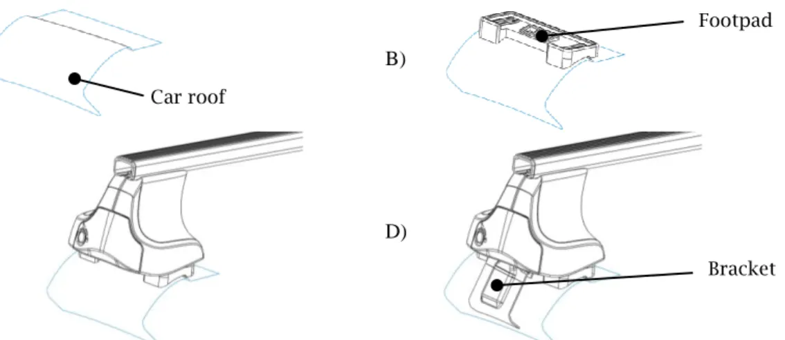
mation specifically targets roof racks that are mounted directly on the car roof, i.e. there are no rails on the car. Consequently, the roof rack product has to be adapted to every car-model it is supporting. The adaption is done by changing two components, the footpad and the bracket. The footpad is a rub-ber pad on which the rack is standing on the roof, and the bracket is used to fix the rack by keeping around the roof end where the doors are (see Fig. 1).
Both safety and geometrical requirements are put on these two components, especially the brack-et, since it has to keep the rack on the roof in case of a crash but still not buckle the car body when fixing the rack.
The company acts on the open market competing with car manufacturers and therefore gets no nominal data of car roofs. Instead, they have to collect geometrical information about car roofs by measuring. When the roof geometry is collected, for a particular car model (A in Fig. 1) a footpad (B) is retrieved or developed in the design automation system. The rack is subsequently placed on the foot-pad in the virtual model (C) and a bracket is retrieved or developed in the design automation system (D). Finally, a car crash simulation is automatically run in order to make sure the safety requirements are met.
The system was automated in three steps. First computer functions were developed for the auto-mation of bracket retrieval. That part of the system has been in use by the engineers since November 2010. Secondly, computer routines for the automation of footpad retrieval were developed. That part of the system is in the beta-testing phase. Finally, the automation of the crash simulations is under development planned to be ready by June 2013. The two first parts of the system are described below and the last one is detailed in section 3.
A) B)
C) D)
Fig. 1: The roof rack product is adapted to new car-models by changing the footpad and the bracket components.
2.1 Retrieving Brackets Automatically
The time to market is critical to the company. A time-consuming step during the development process of a ski-rack is the search for existing brackets, taking up to several hours. Since manual search is a painstaking task with an ever-increasing list of brackets, the engineers tend to skip that step and in-stead just draw a new bracket. However, reusing brackets cut the overall lead-time up to 40%.
There-Footpad
Bracket Car roof
Computer-Aided Design & Applications, 10(a), 2013, bbb-ccc © 2013 CAD Solutions, LLC, http://www.cadanda.com
fore, case-based reasoning (CBR) was applied as a method of searching for brackets [2, 6]. In that sys-tem the human factor was prevented by introducing computer routines for indexing existing brackets into the CBR system by selecting at maximum three edges of the CAD-geometry. Parameters that are automatically recorded when retaining a bracket are the flange curvature, wall thickness, and bending points.
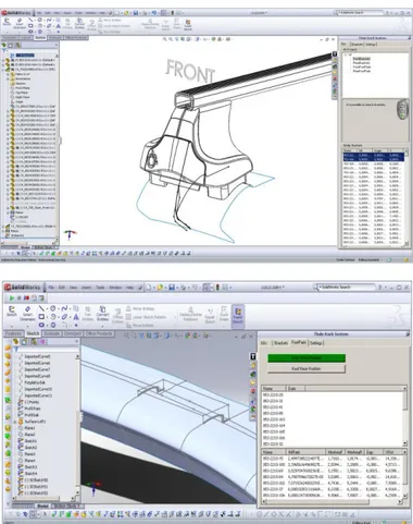
The sub-system for automatically retrieving brackets was finally implemented as an add-in to the Solidworks CAD-system, see top of Fig. 2.
Fig. 2 The automated bracket retrieval is integrated to Solidworks (Top) The automated footpad retrieval is integrated to Solidworks (Bottom) 2.2 Searching Footpads
Since the retrieval of brackets was successfully developed and integrated the thought was that the re-trieval of footpad would be a straight forward task to automate. The approach was to use curvature matching in order to fit footpads to roofs. To mechanical engineers geometry is more than shapes; it is a mean to achieve function(s). In this context, the curvature-based shape matching algorithms failed to find the best position since curvatures do not contain all the information needed to place a footpad on a roof. It is rather the gap between the footpad and the roof that is of interest. Because of this, a new general search method had to be developed. It was the clearance analysis based shape matching [5]. The search for the best position for a footpad on a car roof is completed by first doing some initial preparations, searching for best potential position through clearance analyses, and finally positioning the footpad.
The targeted problem is a three dimensional problem but the shape matching can in this case be done on curves in a 2.5 dimensional manner so that the roof surfaces and the footpads are idealized
Computer-Aided Design & Applications, 10(a), 2013, bbb-ccc © 2013 CAD Solutions, LLC, http://www.cadanda.com
testing phase.
3 HOW TO GENERATE FEM-MODELS AUTOMATICALLY
Developing FEM-models for simulating the behavior of the ski-racks during car collisions are time con-suming and painstaking, calling for automation. It would be helpful if as much information as possible was put into the CAD-model. The main idea is hence to connect a CAD-system to the preprocessor. The connection is based on 1) named CAD-features, 2) a neutral CAD-file, 3) a custom object-model, and 4) generic script files. This section is first describing what initial preparations have to be done and subsequently how the system proceeds when generating the FEM-models.
3.1 Initial preparations
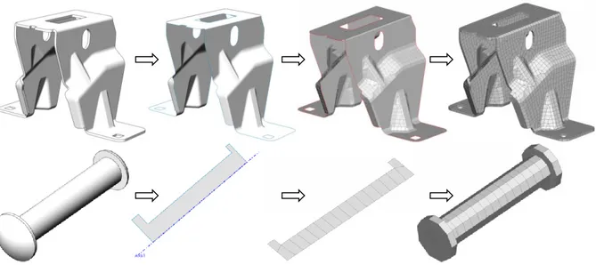
The main idea of the prototype system is to let the FEA-specialists make geometrical features in the CAD-models that represent the idealizations in the final FEA-model. These features (or bodies) can be points, curves, surfaces, or volumes and are named using a name convention. In the example system, all such names begins with “FEM_” followed by a type declaration and additional information, see Tab. 1 and Fig. 3. These features serve as the base for the mesh-model. From Fig. 3 (bottom) it can also be seen that the idealizations do not have to perfectly match the CAD-geometry (that often includes small features unnecessary/undesirable in FEM-model) but can be connected to it making the idealizations update correctly on changes in the CAD-model.
An object model for “MeshPart” objects has to be developed to carry information of all the differ-ent idealization features and a connection to the real CAD-feature object. The object model in the pro-totype system includes BeamParts, SurfaceParts, SheetParts, and RevolveParts (see Fig. 4).
The BeamParts represent parts with beam sections in the FEM-model. The SurfaceParts represent parts with shell sections in the FEM-model. The SheetParts represent parts with solid sections in the FEM-model where the elements are created by offsetting shell elements. The RevovlePart represent parts with solid sections in the FEM-model where the elements are created by revolving shell elements about a certain axis. Additional classes have to be added when extending the system to handle other types of meshes, e.g. extruded or lofted geometry.
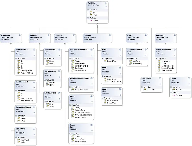
To have a complete FEA-model also constraints, loads, and other definitions has to be specified by the FEA-experts. In the prototype system, this is done using a custom add-in to the SolidWorks-system and results in a collection of “Definition” objects (see Fig. 5) which correspond to what is often called “control cards” in the preprocessor. The benefit of making the specifications of the simulation within the CAD-system is that connections, such as contacts and joints, can be added interactively with the CAD-model and that changes of the CAD-model then can be propagated to the FEA-model.
The “Definitions” object model has to be extended when introducing other types of contacts, con-nections, materials, etc. Fig. 5 is a complete list of them used in the prototype system presented here. In addition to the prepared CAD-models and the object models, also template scripts has to be de-veloped. These templates are used to generate script files to render the final mesh-models. The final script has to include commands to generate all the different MeshParts of which some are rendered in several steps, e.g. the SheetParts which are generated by first meshing its surface and then offsetting that mesh incrementally. To achieve this, the scrip-language had to be extended to include some addi-tional commands for looping through different types of meshparts and for indicating where to insert certain variable values. The command lines between @FOR_EACH_componenttype@ and @END_FOR_EACH@ are copied multiple times in the final script. A complete list of the introduced
Computer-Aided Design & Applications, 10(a), 2013, bbb-ccc © 2013 CAD Solutions, LLC, http://www.cadanda.com
script words are found in Tab. 2 and Fig. 6 shows an example of how the RevolveParts are treated us-ing ANSA-scrip combined with the commands introduced here.
The script template used in the prototype system has the following main sections: First the IGES-file is loaded. Then all “macros” (that is surfaces in the ANSA-terminology) are meshed using meshing scenarios. Surfaces that are subject for further treatment in order to generate sheet metal parts and revolved parts are identified and treated in two for-each loops (one of them are shown in Fig. 6). All beam parts are created by inserting new nodes and connecting them. At this stage, the mesh model is ready. To subsequently generate control cards the name of each part together with its identification number is stored in a log-file. Finally, the ANSA-model is saved and a LS-DYNA model is exported.
Feature Name Resulting mesh
FEM_SURFACE A meshed surface
FEM_OFFSET_2 A meshed surface that is subsequently offset by 2 mm (Top in Fig. 3) FEM_REVOLVED_360_Axis1 A meshed surface that is subsequently revolved 360 deg about Axis1 (Bottom in Fig. 3)
FEM_BEAM_1 Creates a beam of radius 1 mm from a curve Tab. 1: The name convention used in the example prototype.
Fig. 3: Examples of named idealization features and resulting structured mesh.
Computer-Aided Design & Applications, 10(a), 2013, bbb-ccc © 2013 CAD Solutions, LLC, http://www.cadanda.com
FOR_EACH_BEAM_COMPONENT Loop through beam meshparts FOR_EACH_REVOLVE_COMPONENT Loop through all revolved meshparts.
COMPONENTNAME Name of the current component WALL_THICKNESS Wall thickness of the current component x1, y1, z1, x2, y2, z2, angle Coordinates and angles
Tab. 2: Commands that were introduced
Computer-Aided Design & Applications, 10(a), 2013, bbb-ccc © 2013 CAD Solutions, LLC, http://www.cadanda.com
Fig. 6: Example of the extended script-language. @-sign indicates introduced words.
When the CAD-model is prepared with the idealization features, the specifications of the simula-tion are done, and the template scripts are developed, the system is ready to run repeatedly with new combinations of components.
3.2 Run procedure
When executing the system, the first step is to scan the CAD model-tree in order to collect all idealiza-tion features by interpreting feature names. In this step, a collecidealiza-tion of MeshPart objects (see Fig. 4) is created containing information of all the different idealization features and a connection to the real CAD-feature object. While scanning the CAD-model tree, features not being idealization features are hidden away in order to subsequently export an IGES-file containing only the geometry to mesh (this approach is specific for SolidWorks and might differ in other CAD-systems).
A collection of MeshPart objects now exists in the system. The list is then used to generate a script file to be executed by the pre-processor. The script is generated by replacing parameters in the script-template, and by multiplying some scripting-code specific for different MeshParts, as described previously.
Code to generate the specifications of the simulation is finally added to the script file. This step might include adding additional nodes and connecting them, adding material definitions, constraints, and contact conditions. An alternative way is to store the definitions in a separated file referring to the final mesh-model.
When the script finally is ready, it is submitted together with meshing parameters to the pre-processor in batch-mode to generate the complete FEA-model. The FEA-specialists might open the model to examine the result before submitting it to the solver, or (after the system has been verified enough) automatically submit the result to the solver.
4 DISCUSSION
The prototype system presented in this article was developed to integrate SolidWorks, ANSA, and LS-Dyna. Replacing one or several of the systems might change the algorithms since they are depending on the information structures introduced by programmers of the base-systems. Still the overall pro-cess can be used as a template for automation-projects involving FEA.
4.1 Development procedure
The development of the system can be said to include the following seven steps:
1. Identify what type of FEM features are to be automated, including mesh geometry types and FEM-properties.
2. Develop object model for mesh geometries
3. Develop object model for definitions of FEM-properties. Each object should have a func-tion to export its values to either the targeted scripting language or the targeted FEM-solver.
Computer-Aided Design & Applications, 10(a), 2013, bbb-ccc © 2013 CAD Solutions, LLC, http://www.cadanda.com
7. Develop the system to make use of the above steps according to the running procedure These steps were not obvious when first starting the project and iterations between them are una-voidable, but they serve as a good roadmap for future automation projects. One benefit when basing the automation on CAD-features and script-templates is that each expert feels home. The CAD-experts are updating the CAD-models in the CAD-system while the FEA-experts are updating the FEM-model in the FEA-system.
4.2 Running procedure
When running the system the following six tasks are completed:
1. Scan the CAD-model to generate a macro using the macro template based on the idealiza-tion features
2. Execute the macro in the preprocessor to render the mesh model
3. Loop through the list of “Definition”-objects to update them to the resulting mesh (this includes setting correct identification numbers of parts, elements, and nodes)
4. Compile the definition objects to the format of the targeted FEM-solver by using the ob-jects built-in procedure of exporting to text. The mesh model should be appended to the file
5. Optional: Open final model in preprocessor for acceptance by FEA-engineer 6. Submit to solver
Some problems in the prototype system have not yet been completely solved. First, there is a gen-eral problem with the instantiation of parts. When having the same part occurring sevgen-eral times in the SolidWorks-model it is hard to figure out in what order the instances are stored in the IGES-file. This problem sometimes causes the revolved mesh parts to use wrong rotational axis.
Another problem, less important, is that the names of the mesh parts in the final mesh model gets names based on part-numbers of the CAD-model when the FEA-specialists rather prefer to have names based on functions or part-type to make the models easier to deal with. This problem might be solved by introducing a conversion list.
4.3 Future work
Completing the macro-language and the object models would make it possible to automate all types of FEM-models. Introducing a configuration system into the presented system would make simulation-based design readily available.
5 CONCLUSION
This article presented a method to connect a FEA preprocessor with a CAD-system. The connection is achieved by introducing idealization features in the CAD-models that are named using a naming con-vention and script-templates. The article showed a prototype system connecting Solidworks, ANSA and LS-Dyna to automate the crash simulation of ski-racks. When running the prototype system, FEA-models are generated in less than 4 minutes compared to up to a week when done manually. This creases the amount of tested product proposals ultimately increasing the product quality without in-creasing product cost.
The developing method and the running procedure of the described system are general enough to be used as templates for future automation projects.
Computer-Aided Design & Applications, 10(a), 2013, bbb-ccc © 2013 CAD Solutions, LLC, http://www.cadanda.com
ACKNOWLEDGEMENTS
The author expresses his gratitude to Thule Group Corporation and the Knowledge Foundation (KK-stifitelsen) in Sweden for financing the research project. Also as special thank is given to the engineers and managers at the Thule company for technical support.
REFERENCES
[1] Boart, P.: The Enabling of Product Information in the Conceptual Phase, Ph. D. Thesis, Luleå University of Technology, Luleå, 2007
[2] Cederfeldt, M.: Towards a Strategy for Mapping of Design Problems to Suitable Solutions : A Case of Design Automation Using CBR, in Proceedings of the DESIGN 2006 : 9th International Design Conference, D. Marjanovic, Editor 2006: Dubrovnik, Croatia. p. 471-478.
[3] Chapman, C.; Pinfold, M.: The application of a knowledge based engineering approach to the rapid design and analysis of an automotive structure. Adv. Eng. Softw., 32(12),2001, 903-912. [4] Hernández, C.; Arjona, M.A.: Design of distribution transformers based on a knowledge-based
system and 2D finite elements. Finite Elem. Anal. Des., 43(8),2007, 659-665.
[5] Johansson, J.: Combining Case Based Reasoning and Shape Matching Based on Clearance Analyzes to Support the Reuse of Components, 2012.
[6] Johansson, J.; Cederfeldt, M.: Interactive Case Based Reasoning through Visual Representation : Supporting the Reuse of Components in variant-rich products, in Proceedings of Design2012, May 21-24, 2012, Dubrovnik, Croatia2012. p. 1477-1485.
[7] Sandberg, M.: Design for Manufacturing - Methods and Pallications using Knowledge Engineering, Ph. D. Thesis, Luleå University of Technology, Luleå, 2007
[8] Sandberg, M.; Larsson, T.; Åström, P.; Näsström, M.: A design tool integrating CAD and virtual manufacturing for distortion assessment, in 15th International Conference on Engineering Design (ICED05), A. SamuelW. Lewis, Editors. 2005, Institution of Engineers, Australia: Melbourne, Australia. p. 628-630.
[9] Sellgren, U.: Simulation drive design : a functional view of the design process, Ph. D. Thesis, KTH Royal Institute of Technology, Stockholm, 1995
[10] Stolt, R.: CAD-Model Parsing for Automated Design and Design Evaluation, Ph. D. Thesis, Chalmers university of technology, Gothenburg, 2008