Karlstads universitet 651 88 Karlstad Tfn 054-700 10 00 Fax 054-700 14 60 Information@kau.se www.kau.se
Faculty of Technology and Science Department of Chemical Engineering
Asad Abbas
Flow sheeting software as a tool when teaching Chemical Engineering
Degree Project of 30 credit points
Master of Science in Engineering,
Degree Programme in Chemical Engineering
Date/Term: 2011-10-12 Supervisor: Lars Nilsson, KaU Examiner: Lars Järnström, KaU
2
Abstract
The aim of this thesis is to design different chemical processes by using flow sheeting software and to show the usefulness of flow sheeting software as an educational tool. The industries studied are hydrogen, sulfur, nitric acid and ethylene glycol production and a model of drying technique is also included. Firstly, there is an introduction of chemcad as a tool when teaching chemical processes and explanation of each industry which is selected to design. Various production methods for each product are explained and the advantages of the method which is selected to design the chemical flow sheet are discussed. There is also an introduction of the industrial uses of these products formed in Pakistan. The models are designed by using different reactors, heat exchangers, pumps, mixers, boilers and distillation column. The models are designed based upon data taken from literature. The temperature and pressure values are in good agreement with data mentioned in literature. The material balance shown by Chemcad is quite different from data mentioned in literature. Some changes in thermodynamic properties of components in Chemcad software might lead to better agreement between the Chemcad models and literature data. It is not possible to use catalyst in Chemcad to increase the rate of reaction. One possibility is to introduce new components. It is good to use equilibrium reactor when it is required to convert the given component into respective products provided that either conversion of the equilibrium constant are known. It is difficult to study the hidden critical assumptions built in the model when using Gibb’s reactor, as a result there is a deviation in behavior from the system described in the literature. Gibb’s reactor is useful when neither conversion ratio nor equilibrium constant is known.
KEYWORDS: Chemcad, Hydrogen, MEG, Nitric acid, Sulfur, Gibb’s reactor, Equilibrium reactor
Sammanfattning
Målet med detta examensarbete är att designa olika kemitekniska processer genom att använda flowsheeting mjukvara och att visa användbarheten av sådan mjukvara i kemiteknisk undervisning. De industrier som har studerats är produktion av vätgas, svavel, salpetersyra och etylenglykol. En modell av en torkprocess har också tagits med. För det första introduceras Chemcad som en möjlig programvara för att modellera kemitekniska processer och förutsättningarna för varje industri som modelleras gås igenom. Olika produktionsprocesser för varje produkt introduceras och fördelarna med den produktionsmetod som väljs för modelleringsarbetet belyses. Olika användningsområden i Pakistan för produkterna introduceras. Modellerna byggs upp genom att använda olika reaktorer, värmeväxlare, pumpar, blandningskärl, kokare och destillationskolonner. Modellerna byggs upp baserat på designdata från litteraturen. Temperaturer och tryck i de olika processerna visar god överensstämmelse med litteraturdata. I några fall är det stora avvikelser mellan materialbalanserna från Chemcad och designdata från litteraturen. Några förändringar i databasen för olika ämnens egenskaper skulle kunna leda till bättre överensstämmelse mellan Chemcad-modellerna och litteraturdata. Det är inte möjligt att påskynda reaktionshastigheter i Chemcad genom att använda katalysatorer. En möjlighet skulle kunna vara att introducera nya komponenter. Det fungerar bra att modellera kemiska reaktorer som jämviktsreaktorer (Equilibrium reactor) under förutsättning av jämviktskonstanten är känd. Det är svårt att få kännedom om de inbyggda kritiska förutsättningarna i programvaran när Gibbs reaktor (Gibb’s reactor) används, vilket resulterar i en avvikelse mellan det modellerade systemet och litteraturdata. Gibbs reaktor är lämplig att använda när såväl omsättning som jämviktskonstant är okända.
3
Executive summary
Process flow sheeting is a technique to set up and solve mass and energy balances. Before the introduction of computers, the flow sheets were drawn on paper with pencil which takes time. The introduction of computers brought new powerful tools for the Chemical Engineer. With the passage of time more improvement in computer and different flow sheeting software are designed. Flow sheeting software helps to reduce the cost of designing a process in comparison to hand calculations. Chemcad software is available to design the chemical processes in Karlstad University.
A number of chemical processes with great industrial importance and with relevant design data available in literature have been chosen for this thesis. The flow sheets of these processes have been set up in Chemcad to calculate their material and energy balance and compare with the data given in literature. The designing of these respective industries helps to set different examples for those who want to get the knowledge of Chemcad.
These industries are as following • Hydrogen industry • Sulfur industry • Nitric acid industry • Ethylene glycol industry • Drying technique
Production of hydrogen by steam reforming of natural gas is most ongoing practical example from industry. The natural gas is a cheap and readily available raw material for hydrogen production. Production of hydrogen is important for ammonia and urea industry. In Chemcad production of hydrogen is economical if using Stoichiometric reactor (as reformer) it produces high amount of hydrogen as 100 % of methane is converted into CO2 and H2O while some toxic gases CO is also
emitted which create air pollution. On the hand the Gibb’s reactor produces less amount of hydrogen and 75% of methane is converted into CO2 and H2O but with no toxic gases. Gibb’s reactor forms
independent reaction which increases its importance to use in Chemcad.
Designing the flow sheet for sulfur production from acid gas in Chemcad shows that a high amount of sulfur is produced in comparison to literature data. The sulfur produced in literature occurs as diatomic “S2” species while in Chemcad mono atomic sulfur “S” is produced. The sulfur is stored at a
temperature above 121 0C to avoid solidification. The main advantage of producing sulfur is that it is used to produce sulfuric acid. Frasch process is also important technique to produce pure sulfur but this is not economical if sulfur is contaminated with bituminous residue. The purification process is not economical.
Nitric acid is widely used in production of explosives. Only one method is available for the production of nitric acid in industry which is used to design the flow sheet for nitric acid production process in Chemcad. It is ammonia oxidation process. In industry different catalysts are used for the production of nitric acid while in Chemcad it is not possible to increase the rate of reaction by using catalyst. Production of nitric acid may be slightly increased with the recycling of nitrogen containing compound but it is difficult to obtain the converging nitric acid model including recycling in Chemcad.
4
Ethylene glycol is an organic compound and used for the production of polyester fibers, resins and films. Ethylene oxide (cyclic ether) is an important raw material for the production of ethylene glycol. Production of ethylene glycol by hydrolysis of ethylene oxide in Chemcad shows that results are in good agreement with literature. Diethylene glycol and tri ethylene glycol are produced as a by-product in this process. The by-products are used as solvents and drying agents for gases (natural gas). This example is good to study the condensation and distillation process.
Drying technique is used to decrease the moisture content of given solution (component). A rotary counter current dryer is available equipment in Chemcad to discharge the component with low moisture.
This project is an introduction to a process simulation and selection of Chemcad as a tool for those people who have no knowledge about Chemcad. Various reactors are used to design the chemical process flow sheets. Stoichiometric reactor and equilibrium reactor works in an ideal condition. Gibb’s reactor shows more realistic results as it forms an independent reaction. The different models discussed in this report are helpful to study the respective industries. The results shown in these models are beneficial to examine the sensitivity of a system with small changes in their internal parameters. The chemcad software has a possibility to add new components.
5
Symbols and abbreviations
CC Chemcad
H.T.S.C High temperature shift convertor L.T.S.C Low temperature shift convertor EO Ethylene oxide
MEG Mono Ethylene Glycol DEG Diethylene Glycol TEG Triethylene Glycol B.F.W Boiling feed water L.L.V flash liquid-liquid-vapor flash SRK Soave Redlich Kwong
6
Table of Contents
Abstract ...2 Executive summary ...3 1. Introduction ... 10 1.1 Definition of project ... 101.2 Aim of the project ... 10
1.3 Chemcad ... 10
1.3.1 Advantages of Chemcad ... 10
1.3.2 Applications of Chemcad ... 11
1.3.3 Industries using Chemcad ... 11
1.3.4 Chemcad modules ... 11
1.4 Reactors ... 12
1.4.1 Stoichiometric reactor ... 12
1.4.2 Equilibrium reactor ... 12
1.4.3 Gibb’s reactor ... 12
1.5 Method to run Chemcad ... 12
2. Production of hydrogen by steam reforming of natural gas ... 14
2.1 Introduction ... 14 2.2 Hydrogen ... 14 2.3 Uses of hydrogen ... 14 2.4 Production processes ... 14 2.4.1 Electrolysis of water ... 14 2.4.2 Refinery processes ... 15 2.4.3 Partial oxidation ... 16
2.4.4 Hydrogen from Conversion of Metals ... 16
2.4.5 Production of hydrogen by steam reforming of natural gas ... 16
2.5 Selection of process ... 17
7 2.6.1 Raw material ... 17 2.6.2 Equipment ... 17 2.6.3 Desulphurization ... 17 2.6.3 Steam reforming... 18 2.6.4 CO shift conversion ... 18
2.6.5 Carbon dioxide removal section ... 18
2.7 Results ... 22
2.8 Discussion ... 23
2.9 Conclusion ... 24
3. Production of ethylene glycol by hydrolysis of ethylene oxide ... 25
3.1 Introduction ... 25
3.2 Ethylene glycol ... 25
3.3 Uses of ethylene glycol ... 25
3.4 Production of ethylene glycol ... 26
3.4.1 Ethylene Carbonate Process ... 26
3.4.2 Halcon Acetoxylation process ... 26
3.4.3 Hydrolysis of Ethylene Oxide ... 26
3.5 Selection of the process ... 26
3.6 Method ... 26
3.6.1 Raw Materials... 26
3.6.2 Ethylene oxide reacts with water to form ethylene glycol ... 27
3.6.3 Ethylene glycol dewatering ... 27
3.6.4 Purification of ethylene glycol... 27
3.7 Results ... 29
3.8 Discussion ... 29
3.9 Conclusion ... 30
8
4.1 Introduction ... 31
4.2 Nitric acid ... 31
4.3 Uses of nitric acid ... 31
4.4 Production of nitric acid ... 31
4.4.1 Chilean nitrate process ... 31
4.4.2 Birkeland-Eyed process ... 32
4.4.3 Ammonia oxidation process... 32
4.5 Selection process ... 32
4.6 Method ... 32
4.6.1 Raw material ... 32
4.6.2 Ammonia oxidation ... 33
4.6.3 Steam super heater ... 33
4.6.4 Waste heat boiler ... 33
4.6.5 Platinum filter... 34
4.6.6 Preheater ... 34
4.6.7 Cooler and condenser ... 34
4.6.8 Purification of nitric acid ... 34
4.7 Selection of pressure process ... 34
4.7.1 Single pressure process ... 34
4.7.2 The Dual-Pressure Process ... 35
4.7.3 Selecting single pressure process ... 35
4.8 Results ... 37
4.9 Discussion ... 37
4.10 Conclusion... 38
5. Production of sulfur from acid gas ... 39
5.1 Introduction ... 39
9
5.3 Uses of sulfur ... 39
5.4 Production of sulfur... 39
5.4.1 Production from native ores by distillation ... 39
5.4.2 Frasch process ... 40
5.4.3 Iron oxide process ... 40
5.4.4 Activated carbon process ... 40
5.4.5 Claus process ... 40
5.5 Selection of process ... 41
5.6 Method ... 41
5.6.1 Raw material ... 41
5.6.2 Oxidation of acid gas ... 41
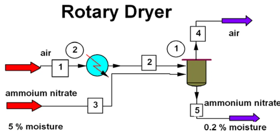
5.7 Results ... 43 5.8 Discussion ... 44 5.9 Conclusion ... 44 6. Rotary dryer ... 45 6.1 Statement ... 45 6.2 Humidity ... 45 6.3 Results ... 45 6.4 Conclusion ... 45 7. Overall conclusion ... 46 Acknowledgement ... 47 Reference ... 48 Appendix ... 49
10
1. Introduction
Modern chemical process industry faces different challenges to work with in engineering environment to improve efficiency of plant and increase productivity. These challenges are raising fuel and feed stock costs, reductions in engineering staff and increasing global competition.
To save time for calculations and simulations flow sheeting software such as Aspen, Hysys, Win Gem, Pro Max 2 and Chemcad are important tools to increase productivity, to improve planning/scheduling with business processes and improve engineering.
1.1 Definition of project
To study different chemical engineering industrial processes, Chemcad is one flow sheeting software which is available in Karlstad University to design different chemical process. In this thesis different chemical processes are designed and the Chemcad results are compared with data provided in the literature.
1.2 Aim of the project
The industries around Karlstad University are related to pulp and paper production. StoraEnso and Metso are two big pulp and paper companies working very close to the university. Students of Karlstad University are more familiar with the pulp and paper production and the ongoing research in this field. The aim of this project is to design other industries in a flow sheeting software and to gain insight into these industries by studying their material and energy balance. This project will help to familiarize the new students of the university with these industries and set different examples in flow sheeting software to be used as a tool when teaching chemical engineering.
These industries are as following • Hydrogen industry • Sulfur industry • Nitric acid industry • Ethylene glycol industry • Drying technique
1.3 Chemcad
Chemcad is an integrated suite of intuitive chemical process engineering software [1]. Chemcad is a powerful and flexible chemical process simulation environment, which is programmed in C++ language.
1.3.1 Advantages of Chemcad
Following are the advantages of Chemcad software.
• Chemcad shows everyday chemical engineering flow sheet of the system hence product quality is increased.
• It helps to design new processes and equipment. • It helps to handle raising fuel and feed stock costs.
11
• Good economic comparison by studying process alternatives. • Reduce engineering staff (advantage to industry).
• All engineering functions united in single software [2]
.
1.3.2 Applications of Chemcad
Some applications of Chemcad software are as following.
• Distillations/extractions (batch and continuous) tower designing. • Reactions (batch and continuous).
• Electrolytic processes.
• Thermo-physical property calculations. • Vapor/liquid/liquid equilibrium calculations. • Equipment sizing (heat exchanger).
• Environmental calculations. • Safety analysis.
• Cost estimations [2]
.
1.3.3 Industries using Chemcad
Chemcad is used as a flow sheeting software in the following industries. • Oil exploration and refining.
• Fertilizer. • Pharmaceuticals.
• Process equipment manufacturers. • Engineering and construction of plant. • Academic university programmers.
1.3.4 Chemcad modules
Chemcad consists of several modules which are using for different purposes. They are as following. CC steady state
The module Chemcad steady state use to design new processes and unit operations to allow steady state simulation of continuous chemical processes from lab scale to full scale.
12
CC dynamics
The module CC dynamic takes steady state simulations to the next level of fidelity to allow dynamic analysis of flow sheets. For example continuous stirred tank reactor.
CC batch
CC batch module allows batch distillation processes to simulate with flexible flow sheets and short learning curves.
CC Therm
CC Therm module is used for designing and simulation of heat exchanger. CC Flash
CC Flash module is used to present the important physical properties out of the large data base sheet very quickly for his daily work. Mixer, divider and flash are important unit operations in CC flash module.
Karlstad University has the license of CC steady state, CC batch and CC Therm modules.
1.4 Reactors
In this thesis we use the Stoichiometric reactor, Equilibrium reactor and Gibb’s reactor.
1.4.1 Stoichiometric reactor
Stoichiometric reactor is used to calculate heat of reaction at a reference temperature and pressure [3] where the equilibrium and kinetic data is not so important but atom and mass balance required. In Chemcad software Stoichiometric reactor required the Stoichiometric coefficients of reaction, key component and conversion ratio.
1.4.2 Equilibrium reactor
Equilibrium reactor is used to calculate chemical and phase equilibrium of reaction where Stoichiometric equation information must be entered. Multiple reactions can be simulated in one equilibrium reactor. Equilibrium reactor is useful when numbers of components are known but few components take part in different reactions. It works in ideal condition. In Chemcad software equilibrium reactor requires the equilibrium coefficients of each reaction.
1.4.3 Gibb’s reactor
Gibb’s reactor is used to determine the equilibrium of reaction from the free energy and heat of reaction is calculated automatically [4]. It works in non-ideal condition where Stoichiometric equations are not required; result is independent reactions. Multiple reactions can be simulated in one Gibb’s reactor. In Chemcad software Gibb’s reactor requires the user to specify the components as well as reactants for independent reactions and inerts.
1.5 Method to run Chemcad
The following is a list of the steps to design and run the process simulation.
1. Click start/ program/ double click on Chemcad v. 5.6.4 and give a new job a name. 2. Click menu entitled format and select engineering unit for example SI unit or Metric unit.
13
3. To add unit operation, click menu mode and select flow sheet. A window is open having different unit operations, feed and product stream arrows, pencil to write and some geometrical shapes.
4. Click the feed (red arrow) on flow sheeting window with the left mouse button and place it on left side of the screen. Add another feed arrow. Select the unit operation used to design in flow sheeting software. Place it just right to feed streams. Click the product icon (purple arrow) on flow sheeting window and place it to the right of unit operation selected to design. Connect the out let of feed stream to the inlet of unit operation and its outlet is connected to product.
5. In order to add component, click menu Thermo Physical and select component list. To select minimum and maximum range for temperature and pressure for the system a window name
Thermodynamics wizard will appear after selecting components. A screen shows SRK (Soave
Redlich Kwong) model, means thermodynamic model.
6. Click the menu specification and specify the feed and cut stream properties (T, P, Component flow rate) and enter the name to that stream.
7. Double left click on equipment and set the given parameter (for example T, P coefficient ratios, key factor, pressure drop) to that equipment.
8. To run the simulator, click the menu run and select run all or just press the icon “R”. A message will come if any error while ignore the warning message.
Well done: simulation is complete.
At last in order to view the report of the simulation, click the menu output and select report. A window will appear and select the report format (word or excel sheet) and go to calculate and give results. A compete report will appear. Save this report.
14
2. Production of hydrogen by steam reforming of natural gas
2.1 Introduction
Hydrogen is an important raw material for the production of other industrial products like ammonia. In Pakistan hydrogen is produced in fertilizer plants and used to produce ammonia and urea. In Chemcad this plant is designed by using different type of reactors in two different cases.
2.2 Hydrogen
Hydrogen was first separated and identified by Boyle in the end of the 18th century; he produced “factitious air” from diluted sulfuric acid and iron [5]. Hydrogen, the lightest and most abundant element, is the first element in the periodic table, has an atomic number of one and an atomic weight of 1.000782519 on C12 scale and the electron configuration is 1s1[6]. The hydrogen (H2) molecule
exists in two forms, in the ortho-form (parallel nuclear spin) and in the para-form (anti parallel nuclear spin) [5].
Hydrogen is very reactive at elevated temperature and with the aid of catalyst [6]. Hydrogen has three isotopes named (1) protium 1H
1
, consists of one valence electron and one proton in nucleus with no neutron [6]. (2) Deuterium (or heavy water) symbol is “D” or 1H
2
, consist of one valence electron and one each of proton and neutron in the nucleus [6]. (3) Tritium symbol is T or 1H
3
, consists of one valence electron and in nucleus there are one proton and two neutrons [6].
2.3 Uses of hydrogen
Hydrogen is an important raw material; it takes part in chemical reaction either by addition (hydrogenation) or by reduction potential, for example in refineries hydrogenation process can be used to increase the hydrogen content of heavy crude oil fractions and lighter fractions can be produced by the reduction of molecular mass. By these processes undesirable elements, such as sulfur, nitrogen and metal can also be removed. Hydrogen can be used also in petrochemical industry for hydrodealkylation, hydrodesulphurization and hydro cracking processes. In the food industry, hydrogen can be used for the production of margarine from liquid vegetable oil by the hydrogenation of oils or fats [6]. Ammonia, an important raw material for the production of urea (fertilizer), is produced by the direct reaction of hydrogen with nitrogen at high temperature. Hydrogen gas also has applications in metallurgy, is used as a shielding gas for welding to isolate the weld from atmospheric gases such as oxygen and nitrogen. Hydrogen has high thermal conductivity, is used for cooling rotors in electrical power generators. In nuclear power plant hydrogen isotopes, especially deuterium is used as a neutron moderator for fission reaction and tritium (hydrogen isotope) is a component of hydrogen bombs [7].
2.4 Production processes
2.4.1 Electrolysis of water
Decomposition of water produced hydrogen (H2) and oxygen (O2) gas in the presence of electric
current. An electric current is produced at 2 different electrodes (made from platinum or stainless steel), hydrogen will appear at cathode (negatively charged) and oxygen will appear at anode (positively charged). These electrodes are separated by a diaphragm which allows the current to flow, but is sometimes gas-tight. Pure water is not suitable to use as an electrolyte because of its low conductivity so aqueous solutions of potassium or sodium hydroxide or sodium chloride etc. can be used [5].
15 Figure 1: Schematic of a water electrolysis cell [5].
a) Anode; b) Diaphragm; c) Cathode; d) Oxygen outlet; e) Anodic electrolyte cycle; f) Anion; g) Cation; h) Cathodic electrolyte cycle; i) Hydrogen outlet; j) Cell wall
Reactions at electrodes At anode 2H2O (l) + 2e- --- H2 (g) +2OH- (aq.) (1) At cathode 2OH- (aq.) --- ½ O2 (g) + H2O (l) +2 e - (2) Cell reaction H2O (l) --- H2 (g) + 1/2O2 (g) (3)
Disadvantages of electrolysis
1. This process is very expensive method because the electrodes used in this process are very expensive.
2. It requires large investment on industrial scale.
3. As electrolytic hydrogen is created indirectly, using electricity as an energy carrier, it is only economic if electricity is extremely cheap. Only a vanishingly small proportion (of the order of 0.1%) of the world's hydrogen is produced directly by water electrolysis.
2.4.2 Refinery processes
Hydrogen is produced from the byproducts of the following types of refinery processes [5] • Cokers and visbreakers
:
• Thermal cracking processes • Catalytic crackers
• Catalytic reformers
Hydrogen is also produced by steam reforming of naphtha. Naphtha is a distillation cut between gasoline and kerosene. This process requires gasification and hydrogenation of sulfur to remove impurities as for natural gas [5].
16
Disadvantages
1. Naphtha is expensive raw material. Also the amount of naphtha varies with market conditions. As more gasoline is produced, less naphtha results same if more kerosene jet fuel is produced less naphtha results.
2. Production of hydrogen by steam reforming of naphtha is not preferred because it is not beneficial with respect to capital cost.
2.4.3 Partial oxidation
Partial oxidation is a reaction of hydrocarbons with oxygen to produce hydrogen and carbon monoxide. Firstly, sulfur or heavy metal contents are removed from the gaseous hydrocarbon because they are difficult to handle in hydrogenation or coking process [5]. This process is not economical because it requires an air separation plant, larger shift conversion, CO2 removal and gas cleanup is
needed [6]. Oxidation reaction CmHnSo + m/2O2 --- m CO + (n/2-o) H2 + o H2S [5] (4)
Disadvantage
Partial oxidation process requires 95-99% pure oxygen ordinarily obtained from air separation plant, which adds to both the plant investment and the operating costs.
2.4.4 Hydrogen from Conversion of Metals
Hydrogen can also be produced by reacting alkali or alkaline earth metal with water or steam. Reaction is as following.
Me + H2O --- ½ H2 + MeOH [5] (5)
Producing hydrogen from metal is mostly in laboratory because metals are expensive to use only for producing hydrogen.
2.4.5 Production of hydrogen by steam reforming of natural gas
Using natural gas as a raw material, which contains small amount of impurities likes sulfur in the form of hydrogen sulfide. Sulfur is highly sensitive to a catalyst in the reformer and shift reactors, removes sulfur by using a zinc oxide bed (350-400 0C). If organic sulfur (merceptans, thiophene) is present, then zinc oxide bed is insufficient for converting sulfur compounds into hydrogen sulfide in hydrogenation stage using 5 % of hydrogen from product steam. Add water in the reformer in the inlet stream. Preheat it up to 520 0C. An endothermic reaction takes place in reformer and temperature at reformer outlet is 870 0C; which produces hydrogen along with carbon dioxide and carbon monoxide. Convert CO into CO2 in high temperature (423
0
C) and low temperature (212 0C) shift reactors [5].
Advantages
It is the simplest and most economical method. 90% of Hydrogen is produced by this method, as low capital investment is required for this process. Natural gas (raw material) is a convenient, easy to
17
handle, hydrogen feedstock with a high hydrogen-to-carbon ratio. This method is nearly about environmental friendly in comparison to other hydrogen production processes.
2.5 Selection of process
For the production of hydrogen I select to set up a model of hydrogen production by steam reforming of natural gas. In Pakistan natural gas is in large abundance and much cheaper than naphtha. The efficiency of the steam reforming process is about 65% to 75%, among the highest of current commercially available production methods.
2.6 Method
2.6.1 Raw material
Hydrocarbons are the main raw material for the production of hydrogen in chemical industry. The two basic raw materials are:
1. Natural gas 2. Steam
Composition of Natural Gas (N.G.): CH4 = 94.68% CO2 = 0.02% N2 = 3.89% Inert = 1.41% H2S = traces
2.6.2 Equipment
Equipments used for the production of hydrogen in Chemcad software are: 1. Heat exchanger (for heating stream).
2. Gibb’s reactor in case 1 (desulphurizer) and in case 2 (desulphurizer, reformer, high & low temperature shift converter).
3. Mixer.
4. Fired heater (heating stream).
5. Stoichiometric reactor in case 1 (reformer).
6. Equilibrium reactor in case 1 (high and low temperature shift converter). 7. Column (CO2 absorber).
Chemcad model for the production of hydrogen is shown in figure 3 and 4.
2.6.3 Desulphurization
The natural gas is available at 38 °C and 40 kg/cm2 containing traces of sulfur. Sulfur is poison to several catalysts. Natural gas is purified in the desulphurization unit (1) to eliminate the traces of sulfur. Natural gas flows through Gibb’s reactor at 400 0C.
18
Reaction in desulphurizer is:
H2S --- H2 + S (6)
In Literature [16] it is mentioned that a zinc oxide bed can be used as a catalyst to remove sulfur but it is not possible to simulate this process in Chemcad.
2.6.3 Steam reforming
The desulphurized natural gas from desulphurizer and M.P. steam at 370 °C and 38kg/cm2 are mixed in mixer. Preheated the stream in the heat exchanger (2) (520 0C) and fired heater (3) (870 0C). Stream enters into reformer (4). An endothermic reaction takes place. Reaction in reformer:
3H2O + 2CH4 870 0C CO + CO2 + 7H2 (7)
Reformer in case-1 is Stoichiometric reactor and 100% conversion of methane. Reformer in case-2 is Gibb’s reactor which converts only 75% of the methane.
2.6.4 CO shift conversion
The reformer gases are at 870 °C and are cooled to 354 0C in heat exchanger (5). Reformer gases at high pressure (38 kg/cm2) are sent to the shift converter.
CO + H2O 423 0
C CO2 + H2 (8)
The conversion of CO to CO2 is done in two stages in two different converters. The first stage is the
High temperature shift convertor (6).
H.T.S.C in case-1 is equilibrium reactor which converts 77.5% CO into CO2.
H.T.S.C in case-2 is Gibb’s reactor which converts only 73.88% CO in to CO2.
The gas is cooled down to a temperature of 212 0C in heat exchanger (7). The second stage is low temperature shift convertor (8).
CO + H2O 212 0C CO2 + H2 (9)
L.T.S.C in case-1 is equilibrium reactor which converts 86.4% CO into CO2.
L.T.S.C in case-2 is Gibb’s reactor which converts 93% CO in to CO2.
2.6.5 Carbon dioxide removal section
Carbon dioxide is removed in absorber (9). 3% mono ethanol amine (MEA) solution is used for the removal of carbon-dioxide. MEA solution enters from absorber top plate and the gas enters from lower plate. Carbon dioxide collected with MEA in the lower part of the absorber.
19 Table 1: Reactors used in hydrogen production model in 2 different cases
Processes Case-1 Case-2
Desulphurization Gibb’s reactor Gibb’s reactor Reforming Stoichiometric reactor Gibb’s reactor H.T.S.C Equilibrium reactor Gibb’s reactor L.T.S.C Equilibrium reactor Gibb’s reactor
20 Figure 3: Chemcad model for the production of hydrogen by steam reforming (case-1)
21 Figure 4: Chemcad model for the production of hydrogen by steam reforming (case-2)
22
2.7 Results
Table 2: Product stream from absorber top
Component Raw material (kg/hr)
Product from absorber (tower) top (kg/hr)
Literature [6] Case-1 Case-2
Hydrogen 0 2786.4 2693.1 2016.5 Methane 5597.6 0 0 1250 CO2 3.24 757 963 362 CO 0 150 143 80 Nitrogen 401.2 402 390 369 Argon 206.6 208 192 188 Sulfur 0.063 0 1.0*10-7 1.8*10-8
Table 3: Conversion ratios in different cases
Component Equipment
Conversion ratios
Literature [6] Case-1 Case-2
CO2 absorption Absorber 95 % 93.6 % 96.8 %
Methane Reformer 100 % 100 % 75 %
CO conversion
H.T.S.C 77.5 % 77.5 % 74 %
23 Table 4: Heat duty for different equipment
Equipment Heat duty (J/hr) Temperature
(0C)
Case -1 Case-2 Case-1 & 2 Desulphurizer 6,01E+08 6,01E+08 400
Reformer 7,35E+10 5,65E+10 870
H.T.S.C 2,03E+08 5,46E+08 423
L.T.S.C -1,22E+09 -1,41E+09 212
2.8 Discussion
1. From the above result (table 2) it is shown that production of hydrogen is higher in case-1 and literature [6]. However it is significantly lower in case-2. Stoichiometric reactor as a reformer is used in case-1, in which 100 % methane is converted into hydrogen. This is an ideal conversion. While Gibb’s reactor as a reformer is used in case-2, in which 75 % methane is converted into hydrogen. Using the Gibb’s reactor in Chemcad means that the composition of the products will be decided by minimizing Gibb’s free energy. It is not possible to enter Stoichiometric coefficient and fractional conversion in a Gibb’s reactor as a result it forms independent reactions.
2. No methane is present at the end in case-1 and literature [6] because 100 % of methane is converted in reformer. While in case-2 a small amount of methane is emitted with product. In case-2 Gibb’s reactor is used as reformer in which components as reactant form independent reactions and conversion fraction is not possible to define so that Gibb’s reactor convert only 75 % of CH4 into CO2, CO and H2 (table 2 &3).
3. This process is highly exothermic so that more steam is produced than consumed. The excess steam generated is used to produce steam itself and for transporting natural gas and combustion process.
4. The CO present in the gas mixture is converted to CO2 in shift convertor, so that CO2 can be
used in urea manufacturing. This conversion is favorable at low temperature 212 0C. To decrease temperature from 870 0C (reformer outlet) to 212 0C is practically difficult to maintain, high length vessel is needed and this wastes a lot of time. It is preferable to convert CO to CO2 in two steps. First at high and then at low temperature. High temperature reaction
allows recovery of the heat of reaction at sufficient temperature level to generate high pressure steam. This is economical to convert CO to CO2 first in high and then in low temperature shift
convertor. As the conversion reaction is reversible at high temperature so only 73.8 % CO is converted in H.T.S.C when using Gibb’s reactor in case-2. On the other hand in case-1 when using equilibrium reactor 77.5 % CO is converted into CO2 as same value is mentioned in
literature because it is possible in equilibrium reactor to enter given fractional conversion so no reversible reaction allowed to take place (table 3).
24
temperature so 93 % CO is converted in Gibb’s reactor. This value is higher than equilibrium reactor value which is 84.6 % in case-1(table 3).
6. Argon and nitrogen are present in raw material (natural gas). They are inert in nature so they still remain in the product stream (table 2).
7. Small amounts of toxic gas such as carbon monoxide is emitted in to atmosphere in both cases 1& 2 (table 2).
8. Heat duty is directly related to conversion ratio. If conversion ratio is high heat duty increases (see table 3 and 4). There must be some additional reactions take place when using Gibb’s reactor in case-2, hence there are some differences in heat duty values in both cases.
(See Appendix, Table 8 & 9 for detail)
2.9 Conclusion
Production of hydrogen with steam reforming of natural gas is beneficial. No emission of toxic gases (sulfur, CO) only CO2 is emitted which is recovered by absorption. So this process is environment
25
3. Production of ethylene glycol by hydrolysis of ethylene oxide
3.1 Introduction
Ethylene glycol is an important raw material for the production of other industrial products. Around 82% of Mono Ethylene Glycol (MEG) consumed worldwide is used in the production of polyester fibers, resins and films. Overall, Ethylene glycol demand has increased by 6-7% since 2001 and is expected to increase at this rate through 2010 [8]. In Pakistan Mono Ethylene Glycol (MEG) is primarily being consumed as raw material for manufacturing of polyester fiber. At present, all the requirement of MEG is being met from imports. In this thesis I study different industrial processes for the production of ethylene glycol. Further study is the production of ethylene glycol in Chemcad software, selecting production of ethylene glycol by hydrolysis of ethylene oxide.
3.2 Ethylene glycol
Ethylene glycol (IUPAC name; ethan-1,2-diol) is an organic compound. Chemical formula is HOCH2CH2OH and molecular mass is 62.07 g/mole. It was first prepared by Wurts in 1859 [9].
Ethylene glycol is an odorless, colorless, sweet tasting liquid but it is toxic and ingestion of MEG can damage the kidneys, heart and nervous system or some time death [10].
3.3 Uses of ethylene glycol
Ethylene glycol is a perfect anti freezing agent in motor vehicles, solar energy units, heat pumps, water heating systems, and industrial cooling systems.
Ethylene glycol is also used in the production of some vaccines but it is not itself present in these injections. It is used as a minor (1–2%) ingredient in shoe polish and also in some inks and dyes [11]. Ethylene glycols are used as a reactant in the manufacture of polyester resins. Many companies’ produces ethylene glycols for use in polyester fiber, films and polyethylene terephthalate (PET) resin production, as well as alkyd resins used in paints [12].
Ethylene glycols including mono ethylene glycol (MEG), diethylene glycol (DEG), and triethylene glycol (TEG) are versatile chemical intermediates used to produce a variety of products for commercial and industrial use, for example
• Adhesives and coatings
• Emulsifiers
• Plasticizers
• Polyurethane foams
• Solvents
• Silicon compounds
• Unsaturated polyester resins
• Used to improve flexibility and drying time of oil based paints coating alkyl resins.
• Mono ethylene glycol is also used as binder for foundry sand molding, and a lubricant for glass- and cement-grinding.
26
3.4 Production of ethylene glycol
3.4.1 Ethylene Carbonate Process
This process is developed in 1970. In this method, ethylene oxide is converted to an intermediate, ethylene carbonate, by reaction with carbon dioxide, which is then hydrolyzed by water to give ethylene glycol. This is an old process [8].
3.4.2 Halcon Acetoxylation process
This process was used in Oxirane plant. It has two-steps for the process, in first step oxidation (90-200 0C) of ethylene in an acetic acid solution, using tellurium and a bromide compound as a catalyst which forms ethylene glycol di-acetate complex. In next step hydrolyzed it to ethylene glycol and acetic acid [8].
Draw back
The process however is not popular due to operating difficulties and difficulties in start up.
3.4.3 Hydrolysis of Ethylene Oxide
Hydrolysis of ethylene oxide is currently one available method for the production of ethylene glycol in the absence of catalyst. The selective raw material EO and water react at high temperature forming ethylene glycol, di ethylene glycol and tri ethylene glycol. Ethylene glycol is dewatered in multi stage evaporator. Distillation column is used for the purification of product mixture with decreasing pressure.
3.5 Selection of the process
Due to cheap and easily available raw material (ethylene oxide) with no complex intermediate formation I have selected hydrolysis of ethylene oxide for setting up a Chemcad model of production of ethylene glycol. There are no operational difficulties. Heat liberated in reactor is used again to heat the raw material in heat exchanger and during purification of end product in distillation column.
3.6 Method
3.6.1 Raw Materials
Raw materials for production of ethylene glycol are: • Ethylene oxide (cyclic ether)
• Water
The production of ethylene glycol consists of three steps:
1. Ethylene oxide reacts with water to form ethylene glycol. 2. Ethylene glycol dewatering.
3. Purification of ethylene glycol to separate mono ethylene glycol, di ethylene glycol, tri ethylene glycol in distillation column.
27
Chemcad model for the production of ethylene glycols is shown in figure 6.
3.6.2 Ethylene oxide reacts with water to form ethylene glycol
The raw material (ethylene oxide, water) at atmospheric temperature and pressure is mixed with makeup water in mixer (1). Preheat the feed in heat exchangers with recycled stream to recover heat first at 148 0C (2) and then at 195 0C (3). Ethylene oxide and pure water are taken into a reactor (4) to produce ethylene glycol with small amount of di-ethylene glycol and tri-ethylene glycols are also produced. Reactions in reactor are as following:
1. CH2OCH2 + H2O HOCH2CH2OH (10)
Ethylene oxide (83% converted) Ethylene glycol
2. HOCH2CH2OH + CH2OCH2 HOCH2CH2OCH2CH2OH (11)
Ethylene glycol Ethylene oxide (12% converted) Diethylene glycol
3. HOCH2CH2OCH2CH2OH + CH2OCH2 HOCH2CH2OCH2CH2OCH2CH2O (12)
Diethylene glycol Ethylene oxide (5% converted) Triethylene glycol Equilibrium reactor is used for the reactions to take place.
3.6.3 Ethylene glycol dewatering
Ethylene glycol is dewatered by using multi stage evaporators. The water glycol mixture from the reactor is fed to the first stage of a multi stage of the evaporator. Ethylene glycol is dewatered in first stage (5) by using steam as a heating medium. In second stage (6) dewatering takes place at low pressure and final stage (7) operate under vacuum. The evaporated water is recovered as condensate. Ethylene glycol mixture is fed to L.L.V flash (8) to separate water from glycol.
3.6.4 Purification of ethylene glycol
Ethylene glycol is purified in distillation column (9) (8 plates). Feed enter from plate no 3. Mono ethylene glycol is recovered from column top and diethylene glycol and triethylene glycols are recovered at column bottom. Small amount of ethylene glycol is evaporated with water, which is separated by using L.L.V flash (10).
28 Figure 5: Block diagram for the production of monoethylene glycol
29
3.7 Results
Table 5: Comparison between literature and Chemcad results
Components Raw material (kmol/hr) End product (kmol/hr)
Literature [8] Chemcad results
EO 189.3 0 Almost zero H2O 1 926.5 - - MEG - 134 131 DEG - 13.3 12.5 TEG - 9.5 9.4
3.8 Discussion
1. The above results (table 5) show that production of mono ethylene glycol, diethylene glycol and triethylene glycol at the end of Chemcad software and data mentioned in literature [8] are almost same.
2. This process is highly exothermic (heat liberated). Heat is used to produce steam and preheat the raw material in heat exchanger (2). Steam added to first evaporator to evaporate water is also used to preheat the raw material and is recovered after using L.LV flash (9).
3. Production of ethylene glycol by hydrolysis of ethylene oxide will also lead to production of small amounts of co-products such as DEG and TEG; to prevent these by-products it is good to use excess water. If the given makeup value is decreased the mono ethylene glycol is little more produced while the by-product such as diethylene glycol is also more produced and process is not converged.
4. The pressure of the reaction in reactor must be controlled to avoid the vaporization of ethylene oxide (raw material) in aqueous solution.
5. Distillation is one of the techniques to separate components on the basis of their boiling point. The component with low boiling point is collected at tower top and component with high boiling point is received at lower part of the tower. In our case the tower has 8 plates to purify the MEG. The feed containing MEG, DEG, TEG and water enters through plate no 3. Ethylene glycol with low boiling point (197 0C) evaporate to tower top and is collected in condenser, where it condenses and to achieve high efficiency of distillation, part of the condensate is sent back to the tower as reflux and sprayed on tower top. The reflux liquid flowing down provides cooling and condensation to vapors flowing upward hence efficiency of tower increases and product obtained from tower top after
30
condensation is known as distillate, is more pure. The low volatile components such as DEG and TEG are collected at tower bottom. Reboiler is installed at bottom to vaporize the component, more volatile (MEG) rising to tower top hence more separation and purified product obtained at tower top. The heat curve (figure 12) shows the same results. Condenser decreases the temperature of MEG vapor, condensate it and is collected as liquid. Reboiler increases the temperature as a result high volatile component rise up and low volatile component are collected at bottom.
(See Appendix, Table 10 & 11 for detail)
3.9 Conclusion
Production of mono ethylene glycol with hydrolysis of ethylene oxide is a good example to study by using the Chemcad software. Results are in good agreement. Around 60 % of the ethylene glycol produced in world is by hydrolysis of ethylene oxide. It is good to install ethylene glycol plant close to ethylene oxide production plant.
31
4. Production of nitric acid by oxidation of ammonia
4.1 Introduction
Nitric acid is one of the most important and widely used acids for the production of other chemical products such as in production of explosives, plastics, fertilizers (ammonium nitrate), dyes and synthetic fibers. In Pakistan Pak Arab Fertilizer Multan and POF Wah Cantt, are big twin players for the production of nitric acid. Production of nitric acid in Pak Arab Fertilizer Multan is 1380 ton/day
[16]
. In this thesis work I study different methods for the production of nitric acid and select ammonia oxidation process to create flow sheeting model of nitric acid production on large scale.
4.2 Nitric acid
Nitric acid (HNO3) also known as aqua fortis (strong water), is colorless when pure but is yellowish
when it is contaminated. Nitric acid is mostly used as strong oxidizing agent. It is highly corrosive and toxic. Strong acid causes severe burn when in direct contact with the skin so it is important to handle it with great care especially protecting the eyes. It is present in nature in the form of nitrate salts [13]. In ancient times nitric acid was used to separate gold and silver.
4.3 Uses of nitric acid
Following are the uses of nitric acid.
1. Nitric acid is used as a nitrating agent in explosives such as T.N.T., gun cotton and nitro glycerin [13] [14].
2. Nitric acid is used as chemical with alcohol in metallurgy for etching designs on metals like brass, copper, bronze and pickling agent for stainless steel [13] [14].
3. It is also used in the manufacturing of nitrogen fertilizer (high nitrogen content up to 33.5 %), dyes, drugs and plastics [15].
4. Nitric acid with combination of hydrochloric acid is forming an element called aqua regia, which is used to dissolve noble elements for example gold and platinum [14] [15].
5. It is used to determine the difference between heroin and morphine in a colorimetric test [14]
[15]
.
4.4 Production of nitric acid
4.4.1 Chilean nitrate process
Chilean nitrate or sodium nitrate reacts with sulfuric acid forming nitric acid at high temperature. This is an old process.
NaNO3 + H2SO4 HNO3 + NaHSO4 (13)
Drawback
The product formed at end loses its water at high temperature so salt is left behind in the form of solid, which is difficult to remove due to scaling. This process also forms impurities such as nitrogen dioxide.
32
4.4.2 Birkeland-Eyed process
In this process nitric acid is produced from air at high temperature. High temperature is obtained by passing an alternating current through an electric arc suppressing the magnetic field created by it. Electricity is provided by hydroelectric power station. Reactions for production of nitric acid are as following.
N2 + O2 2NO (14)
2NO + O2 2NO2 (15)
This nitrogen dioxide is then dissolved in water to give rise to nitric acid.
3NO2 + H2O 2HNO3 + NO (16)
Nitric acid is then purified by fractional distillation.
Drawback
It is difficult to maintain high temperature up to 3000 0C. This process produces only 68% nitric acid. Remaining is water and nitric oxide.
4.4.3 Ammonia oxidation process
This process is carried out in two stages. First stage is the oxidation of ammonia at high temperature in the presence of catalyst platinum with 10% rhodium producing nitric oxide and water. This is an exothermic reaction.
4NH3 (g) + 5O2 (g) 4NO (g) + 6H2O (g) (17)
Second stage is oxidation of nitric oxide to form nitrogen dioxide gas. This gas is then readily absorbed by the water to yield nitric acid.
2NO (g) + O2 (g) 2NO2 (g) (18)
3NO2 (g) + H2O (l) 2HNO3 (aq.) + NO (g) (19)
Nitric acid is purified by distillation. Nitric oxide is recycled.
4.5 Selection process
Only one method is available for the production of nitric acid on large scale and this is the ammonia oxidation process. The raw material (ammonia) used for this process is easily available in fertilizer plants. Efficiency of this process is 96 %. So this process is economical. Only NO is emitted through this which is recycled and converted into NO2. The reactions in this process are exothermic so heat is
liberated which is used to preheat the raw material.
4.6 Method
4.6.1 Raw material
Raw materials for production of ethylene glycol are: • Ammonia
33
• Water • Oxygen
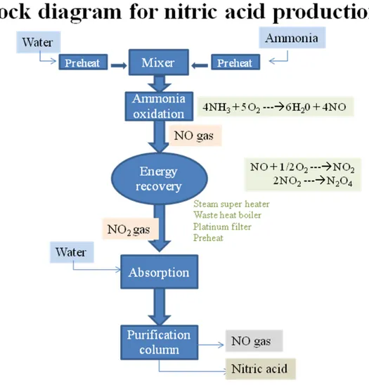
In Chemcad software nitric acid plant is designed by using compressor, equilibrium reactors, heat exchangers and distillation column. Chemcad model for the production of nitric acid is shown in figure 8.
4.6.2 Ammonia oxidation
The raw material ammonia (NH3) enters the system at a low temperature (288 K) (stream 3) and is
vaporized by using steam in 2 heat exchangers (1) and temperature is raised to 450 K. The air is split into 2 parts, primary air (ammonia oxidation, stream 1) and secondary air (acid bleaching, stream 28). Primary air at temperature (303 K) is passed through compressor (2) with the exit pressure of 6 bars and preheats it up to temperature 535 K in heat exchanger (4). The pre-heated air is mixed with vaporized ammonia in mixer (3) and it is ensured that complete mixing of raw material has taken place. This mixture is entered into reactor (4) for oxidation of NH3 and the exothermic reactions
formed. These reactions are as following.
4NH3 + 5O2 6H20 + 4NO (20)
95 % ammonia is oxidized to NO and water.
4NH3 + 3O2 6H20 + 2N2 (21)
Remaining 5 % ammonia is oxidized to nitrogen and water.
These reactions are operated at high temperature and exothermic in nature so that a large amount of heat is liberated. The second stage is the formation of nitrogen dioxide which is favorable at low temperature. First the heat liberated from the reactor is recovered.
4.6.3 Steam super heater
The gases formed in reactor are passed through steam super heater section (5). The gases are entered into the heat exchanger and the temperature drops to 918 K and heat is transferred to water forming steam and oxidation of nitric oxide in reactor take place (temperature drop to 869 K). Reaction is as following.
NO + 1/2O2 NO2 (22)
5 % NO is oxidized to nitrogen dioxide.
4.6.4 Waste heat boiler
More heat is recovered in waste heat boiler section (6). The gas is passed through 2 reactors and the temperature of the gas drops to 553.15 K. Reaction in the first reactor is oxidation of 15 % nitric oxide to nitrogen dioxide (equation no 22). The reaction in the second reactor is 3 % conversion of nitrogen dioxide to nitrogen tetra oxide (equation no 23). Production of nitrogen tetra oxide is side reaction, which is not useful for production of nitric acid. In industry the oxidation of nitric oxide and conversion of nitrogen dioxide to nitrogen tetra oxide takes place in one reactor but in Chemcad it was necessary to use one reactor for modeling the main reaction and one for the side reaction.
34
2NO2 N2O4 (23)
3% NO2 is converted into nitrogen tetra oxide.
4.6.5 Platinum filter
In this section gold/palladium alloy is used in industry to trap platinum. Platinum is carried in the reaction gas as it was used as a catalyst in ammonia oxidation reactor but it is not possible to use catalyst in Chemcad. 3% nitric oxide is converted into nitrogen dioxide (equation no 22) and 0.4 % nitrogen oxide is converted into nitrogen tetra oxide (equation no 23) (side reaction). In industry the platinum filter (7) is used to minimize the conversion of nitrogen dioxide to nitrogen tetra oxide.
4.6.6 Preheater
The platinum catalyst is expensive so the remaining conversion of nitric oxide to nitrogen dioxide is at low temperature and the heat liberated after platinum filter is used for steam production. In pre-heater section (8) 15 % nitric oxide is oxidized to nitrogen dioxide (equation no 22) and as there is no catalyst in this section 7 % nitrogen dioxide is converted into nitrogen tetra oxide (equation no 23) and temperature drop to 440 K occurs.
4.6.7 Cooler and condenser
The gas is then entered into the cooler and condenser (9) to produce more nitrogen dioxide. The gas is cooled down to 333 K which is very low temperature and this is in the range which is favorable for the oxidation of nitric oxide into nitrogen dioxide (equation no 22) and the conversion of nitric oxide is 94 %. Only 7 % of the nitrogen dioxide formed is converted into nitrogen tetra oxide (equation no 23) (side reaction). At this low temperature 55 % of the nitrogen dioxide present in the gas mixture is hydrolyzed to nitric acid. The reaction is as following.
3NO2 + H2O NO + 2HNO3 (24)
The product stream is mixed with secondary air for oxidation of nitric oxide to nitrogen dioxide in reactor (10) to reduce the emission of nitric oxide to air. Further conversion of this nitrogen dioxide to nitric acid takes place in reactor (11).
4.6.8 Purification of nitric acid
The nitric acid is purified in distillation column (12) by using make up water at atmospheric temperature. The nitric acid is collected at the bottom of the distillation column.
4.7 Selection of pressure process
Production of nitric acid by oxidation of ammonia is divided into 2 different processes.
4.7.1 Single pressure process
• Medium pressure process
The ammonia is oxidized at that pressure, which is obtained at the outlet of the un-cooled air compressor. The process is used to recover maximum energy which is used to produce steam.
35
• High pressure process
The ammonia is oxidized at a high pressure, obtained from the inter-stage cooling system in a multistage compressor. The yield of nitric acid d in this case is very low as compared to medium pressure process. This process is used when capital investment is low.
4.7.2 The Dual-Pressure Process
This process is used to take advantage of two factors:• At low pressure, higher amount of ammonia is oxidized.
• At higher pressure in absorption section (distillation column) more nitric acid is absorbed.
4.7.3 Selecting single pressure process
In this model we select the single pressure process (medium pressure process), for maximum recovery of energy and higher oxidation of ammonia. This process is not complicated and single stage compressor is used.
36 Figure 8: Chemcad model for the production of nitric acid
37
4.8 Results
Table 6: Comparison between literature and Chemcad results
Components Raw material (kmole/hr)
End product (kmole/hr) Literature [17] Chemcad results
Nitric acid 0 397 273 Nitrogen 3350 3360 3359 Oxygen 890 79.5 151 Water 83 16.5 - Ammonia 419 0 0 NOx 0 1.7 84 N2O4 0 16.3 20.3
4.9 Discussion
The above result (Table 6) shows that production of nitric acid in Chemcad and end values in literature
[17]
are different.
1. The above table shows that raw material (ammonia) is completely consumed in both cases. This is the reason that single pressure process is used for complete oxidation of ammonia. For the oxidation of ammonia equilibrium reactor is used in Chemcad as the conversion is almost 100 %. The Gibb’s reactor oxidizes the component independently to maintain the equilibrium. The conversion ratios for the other reactions are also mentioned in literature [34]; this is the reason that equilibrium reactors are used for different steps proceeding to production of nitric acid.
2. Oxidation of ammonia is highly exothermic (heat liberated). Heat is used to produce steam and pre heat the raw material (ammonia) in heat exchanger (1).
3. This process also produces small amounts of by-product such as nitrogen tetra oxide in equation no 10. This by-product conversion may be reduced if the oxidation of nitric oxide to nitrogen dioxide takes place at high temperature. On the other hand the oxidation of nitric oxide is favorable at low temperature.
4. This process also produces nitrogen containing compounds which are poisonous not only to catalyst used in industry but they also increase the air pollution. These compounds are nitric oxide and nitrogen dioxide which are remaining in small amounts at the end. These amounts will be reduced if they are recycled to produce more nitric acid. This is the reason that values obtained from Chemcad software are high because the nitrogen compounds are not recycled. It is difficult to obtain a converging Chemcad model if recycling is included in the model.
38
5. The nitric acid produced by oxidation of ammonia is lower in Chemcad than literature. As nitrogen containing compounds are not recycled in Chemcad and more oxygen is remaining at the end so nitric acid production is lower in Chemcad than according to the literature [17] reference.
(See Appendix, Table 12 & 13 for detail)
4.10 Conclusion
Production of nitric acid is heavily dependent on the demand for the fertilizer. Ammonia oxidation process is economical as heat liberated is recovered and raw material (ammonia) is easily available in Pakistan. Recycling of nitrogen containing compounds increases the production of nitric acid while it is difficult to obtain a converging Chemcad model if recycling is included in the model.
39
5. Production of sulfur from acid gas
5.1 Introduction
Sulfur is present in nature in the form of different compounds. About 0.052 % of the earth crust is sulfur [19]. Acid gas (H2S) emitted from the petroleum industry, is an important raw material for the
production of sulfur.
5.2 Sulfur
Sulfur is a non-metallic element and is the second element of group VI below oxygen and above selenium, with valence –2 to +6, atomic number 16 and atomic mass 32.064. Sulfur is present in iron pyrites, gypsum, sulfide ores, wool, hair, egg, coal, petroleum and natural gas.
Elemental sulfur occurs in several different allotropic forms most common are the rhombic and monoclinic forms which differ in solubility, relative density, crystalline form. Rhombic sulfur is stable at atmospheric pressure up to 95.5 0C, at which transition to monoclinic sulfur is then stable up to its material melting point of 114.5 0C [18].
5.3 Uses of sulfur
Most of the sulfur is used for the production of sulfuric acid. More than 50 % of the sulfur which in turn converted to sulfuric acid is used for the production of fertilizers (together with pesticides, insecticides, and fungicides). Agriculture consumes more than half of the sulfur produced. The remaining sulfur goes into the production of detergents, pharmaceuticals, petroleum catalysts, synthetic resins, titanium pigments, viscose, acetates, and explosives [19]
Some other uses are:
.
• Medically in sulfa drugs and in many skin treatment ointments, bar soaps, lotions and creams
[20]
.
• In the production of matches, vulcanized rubber, dyes and gun powder.
• Using in salt, sodium thiosulphate, Na2S2O3·5H2O, commonly called hypo, is used in
photography for fixing negatives and prints mostly in Asian country. This technology is now decreasing a lot with digital camera.
• Sulfur reacts with various inert mineral fillers, forms special cement used to anchor metal objects, for example railings and chains.
5.4 Production of sulfur
5.4.1 Production from native ores by distillation
Under the special geological conditions, it is difficult to melt out the sulfur from its ores in an externally heated vessel. It is good to distill the sulfur out of the ore. The ore is heated by direct contact with a solid surface. Sulfur is also a poor conductor of heat having some temperature limitations imposed by viscosity, so it requires large heating surface. Another process is heating with hot inert gases. After some practical tests, it is impossible to exclude oxygen and moisture completely, which form sulfur dioxide and sulfuric acid foam. These by-products are strongly corrosive; one proposal involves using rotary kilns and recycling the sulfur dioxide containing waste gases.
40
Drawback
These processes are not favorable with current sulfur price levels.
5.4.2 Frasch process
This process is developed by Herman Frasch between 1894 and 1903. The principles of Frasch process is injecting large quantities of hot water directly into the deposits and then pumping the molten sulfur to the surface. A well is drilled where three coaxial pipes are introduced into the bore hole. The outermost pipe (200 mm diameter) reaches to the bottom of the bore hole and its lower end is perforated with slots. Hot water at about 165 0C under sufficient pressure (2.5-3 MPa) to keep it from the boiling is injected via the outermost pipe. Hot air is introduced via the innermost pipe as the molten sulfur´s greater density and the water pressure alone is unable to force it to the surface. Sulfur melts (115 0C) and flows into the middle pipe. The sulfur extracted by this process is 99.8 % pure and light yellow in color [19].
Drawback
If sulfur is contaminated with traces of bituminous residue, then further purification is not economical. The contaminated sulfur form is called as dark sulfur. Production of sulfuric acid by using this dark sulfur form leads to acid mists with moisture from the combustion of the organic materials, which can cause corrosion and pollution.
5.4.3 Iron oxide process
The iron oxide process is one of the oldest processes used for the removal of sulfur from industrial gases. In this process H2S is reacted with hydrated ferric oxide forming ferric sulfide. Upon exposure
to oxygen sulfide is oxidized to elemental sulfur and ferric oxide. Ferric oxide is again reacted with H2S to produce more sulfur.
Drawback
The elemental sulfur form is not pure as it covers most of the surface of the oxide and fills most of the interstices between the oxide particles.
5.4.4 Activated carbon process
This process was developed by F.G. Fabric industries. Activated carbon is used as a catalyst in the oxidation of H2S to elemental sulfur. The sulfur deposit on activated carbon is removed by extraction
with an appropriate solvent and the carbon is reused until the carbon particles are excessive. The advantage of using activated carbon is the high purity of produced sulfur.
Drawback
The catalyst carbon is deactivated rather rapidly by deposition on the particle surface so that compete removal of all such materials from the gas prior to treatment is necessary. This process is not used on large scale but it is being used for treating large quantities of blue water gas and this process is originally designed for H2S removal
[18]
.
5.4.5 Claus process
This process was invented on 1883. In Claus process H2S was reacted with air (O2) in the presence of
41
H2S + 1/2 O2 S + H2O (25)
This process was highly exothermic reaction. It was difficult to control as large amount of heat was liberated and sulfur recovery efficiencies were low. In 1936 some modifications were developed in Claus process. It was first used in industrial scale in USA in 1950.
There are two principal process variations.
Straight through process
In this process all of the air and the acid gas pass through the combustion zone. This process is used when high hydrogen sulfide content is present.
Split through process
In this process all of the air and at least one third of the acid gas pass through the combustion zone with the remaining acid gas being sent to the reactor. This process is used when low concentration of hydrogen sulfide is present [18].
5.5 Selection of process
For the production of sulfur I select the Claus process (split through process). This process is able to convert a toxic and environmentally undesirable component, hydrogen sulfide, into elemental sulfur. This process produces sulfur of extremely good quality. The Claus process recovers almost all sulfur so this process controls air pollution and further cleaning of the exhaust gases is not necessary.
5.6 Method
5.6.1 Raw material
Raw materials for production of sulfur are: • Hydrogen sulfide
• Water • Oxygen
In Chemcad sulfur is produced by using equilibrium reactor, multi stage condensation system to condense sulfur and using mixer to mix the sulfur collected at the end of each condenser. Chemcad model for the production of hydrogen is shown in figure 10.
5.6.2 Oxidation of acid gas
Air (oxygen) (stream 28) is supplied through compressor (11), which is one third of the H2S (raw
material) (stream 1) and are mixed in mixer (12). The feed stream is preheated in furnace (1) up to 8150C. Elemental sulfur is formed along with oxidation of H2S to SO2 in reactor (2) (equilibrium
reactor). CO2 is formed from oxidation of hydrocarbon.
Reactions in oxidation reactor are as following.
1. H2S + 3/2 O2 SO2 + H2O (26)
42
2. CH4 + 2O2 CO2 + 2H2O (27)
90 % CH4 is converted into CO2.
3. 2H2S + SO2 3 S + 2H2O (28)
30 % H2S is converted into sulfur
In Chemcad a monatomic species S with molar mass 32 g/mole is used instead of diatomic sulfur. These reactions take place at atmospheric pressure.
The combustion products flow through a series of condensers to condense sulfur. Condense the gases by B.F.W in condenser-1 (3) and leaves at temperature of 182 0C. Sulfur is collected at bottom and discharged to the mixer (10). Remaining gases are reacted in reactor (4) to convert H2S (45%) into
Sulfur, using reaction no 3. This stream is condensed in condenser (5) to collect sulfur at 148 0C. Two more reactors (6) and (8) are used for conversion of H2S to sulfur and condensation takes place in
condensers (7) and (9) to collect sulfur as a product and discharge it to mixer (10). Gases (mainly inert gases) are collected from top of the final condenser (9) together with a small amount of unconverted sulfur compounds.
43 Figure 10: Chemcad model for the production of sulfur from acid gas
5.7 Results
Table 7: Comparison between literature and Chemcad results
Components Raw material (kmole/hr)
End product (kmole/hr) Literature [18] Chemcad results
S 0 42.31 79.22 H2S 86.806 1.73 5.34 CH4 0.84 0 0 CO2 55.02 55.86 55.86 N2 167.97 167.97 167.97 H2O 4.84 90.76 87.5 O2 44.65 0 0.17 SO2 0 0.43 2.2