SELFSIMILAR SOLUTIONS FOR STRESS DRIVEN
MATERIAL DISSOLUTION
P. Ståhle and A. P. Jivkov Solid Mechanics, Malmö University
SE205 06 Malmö, Sweden pers@ts.mah.se
Abstract
During corrosive dissolution of metal ions from a body surface, an oxide compound is produced. This compound forms a protective film that reduces the dissolution rate. When a fraction of a millimetre depth is dissolved the dissolution rate become insignificant. However, repeated loading will damage the film with continued dissolution as a result. In connection with this a threshold strain is assumed to exist. This paper proposes a model where electro-chemical processes and the mechanical load work together in forming a corrosion pit. The ratio between the threshold strain and the remotely applied strain is shown to control the shape of the pit. For small applied strains cracks are formed. A crack evolving from a surface irregularity is studied. The growth rate of the crack is determined by the dissolution rate at the crack tip. No crack growth criterion is needed. The growing crack is itself creating conditions for strain concentration, which leads to a high crack growth rate. The model simulates how dissolution forms a pit that grows to become a crack in a single continuous process. For small loads the crack growth rate is independent of applied load.
Introduction
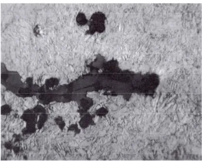
As much as 25% of all accidents in process industry reported to the Swedish Plant Inspectorate are caused by stress corrosion crack growth, Bergman et al. [1]. The situation is believed to be similar in all industrialised countries. Because crack growth occurs at low load the crack is usually not known before the accident, which contribute to the severity of the problem. Figure 1 shows the tip of a transgranular corrosion crack in a nuclear power plant feed-water pipe.
In stress corrosion, loss of atoms to the environment leads to crack growth. This is a dissolution process that starts if bare metal surface is exposed to aggressive environments (cf. Roberge [2]). Fortunately, a passivating process compete with the dissolution. Thus, an impermeable film of mainly metal oxides and hydroxides formed by dissolved metal reduce the dissolution rate. Even though the thickness of this film is typically not more than 1 to 4 nm it reduces the rate of dissolution several orders of magnitude. An intact protective film increases the lives of the structural members tremendously. When a fraction of a millimetre depth is dissolved the dissolution rate become insignificant. However, repeated changes of the electrochemical conditions, or cyclic mechanical load may damage the film, which leads to a (comparatively) rapid material loss. The failure of the film due to mechanical loading is the basis for a widely used hypothesis for stress corrosion cracking, where the crack advance is believed to be the result of metal dissolution, localised at the surface experiencing the highest strains, as in Perkins [3] and Turnbull [4]. Recent experimental reports by Kussmaul et al. [5] and by Heldt and Seifert [6] show that active loading in terms of either
monotonically increasing or fatigue load is an essential prerequisite for continuous corrosion crack growth.
The rate of the dissolution as a function of the strain rate is not known. However, the dissolution rate is believed to be increasing with increasing strain rate. In the present report a simple linear relation between dissolution rate and strain rate is assumed. In addition to this, a threshold strain is introduced, below which no damage occurs.
The proposed model was earlier used to study nucleation of cracks from surface pits in elastic materials, and in elastic-plastic materials (cf. Jivkov and Ståhle [7] and Jivkov [8]). The results of these works show that the model leads to strain and dissolution localisation, resulting in the nucleation of a crack. The present study formulates a set of governing equations that suggest a self-similar growth of the pit (or crack). A plausible solution for low load consisting of a crack with practically parallel surfaces and a half-circular tip is examined. This solution is compared with corresponding finite element results.
Model
Consider a large body with a straight traction free edge. At large distances a uniaxial stress is applied parallel with the edge. The material is assumed to be linear elastic with the modulus of elasticity E and Poisson's ratio ν. Plane conditions are invoked. Here plane stress is selected but the result for plane strain is readily found by replacing E with E/(1-ν2
) and ν with ν/(1-ν). Stresses are defined via tractions as
€
Tα = nβσβα , (1a)
where Tα is the traction vector acting on a surface with the outward normal nβ. The stresses are assumed to be in equilibrium, satisfying the equation
€
σαβ,β= 0 . (1b)
Strains are assumed to be small and defined by
FIGURE 1. Transgranular corrosion crack with crack length a ≈ 7 mm and notch radius ρ ≈ 5 µm.
€
εαβ =1
2(uα,β+ uβ,α) . (1c)
Stresses and strains are linearly related through Hooke's law as follows
€
σαβ= E
1+ νεαβ + νE
1− ν2δαβεγγ . (1d)
Indices in (1a) to (1d) assume the values 1 and 2. The boundary conditions are the load at large distances
€
T1= 0 and T2=σ∞, at x12+ x22→ ∞ , (2a)
and along the traction free edge
€
T1= T2= 0 , at x1= 0 . (2b)
In addition to this, material is removed at a rate υ proportional to the stretch ε of the surface
€
υ = Rd(ε−εf) = Rd
σ−σf
E , for ε - εf > 0 and υ = 0 for ε - εf ≤ 0 (3) where Rd is a rate parameter. A threshold strain εf is introduced in (3). The stresses
€
σf = Eεf
and
€
σ= Eε . The evolving surface is assumed to remain traction free.
By introducing non-dimensional tractions, stresses and dissolution rate as follows
€ ˆ T i =Ti/σf , € ˆ σ =σ/σf , € ˆ σ ∞=σ∞/σf , € ˆ σ ij=σij/σf and € ˆ υ =υ/(Rdεf). (4)
Displacements and strain become obsolete and (1c) and (1d) is reduced to
€
ˆ
σ αα,ββ= 0 (6)
The requirement is that the stresses should fulfil the equation of equilibrium, i.e.,
€ ˆ T α = nβσ ˆ αβ, where € ˆ σ αβ,β = 0 . (7)
The boundary conditions (2) may be written on a non-dimensional form as follows
€ ˆ T 1= 0 and T ˆ 2= ˆ σ ∞, at x12+ x22→ ∞, (8a) € ˆ T 1= ˆ T 2= 0 , at x1= 0 . (8b)
Material is removed at the rate expressed as
€
ˆ
υ =( ˆ σ −1) (9)
Obvious now is that the results for a given initial geometry depend only on load, i.e., on
€
ˆ
σ ∞. With given stress boundary conditions also the material parameters E and ν become obsolete. Thus, the problem is defined by the initial geometry and the equations (6) and (7) with the boundary conditions (8) and evolution of the body in accordance with (9).
Analysis
In many cases no relevant length parameters exist, e.g., when a pit initiate and develops from a small indentation or a scratch in a straight edge. During initiation the geometry of the initial
indentation is relevant. However, when the pit has grown several times the linear extent of the indentation no other length than the extent of the pit should influence the continued growth. If the situation immediately after initiation is excluded the solution must be selfsimilar, i.e. all lengths of the solution scale with each other or, e.g., the pit depth.
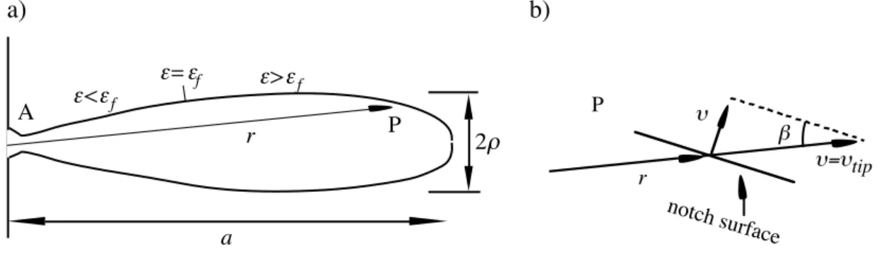
One implication is that the dissolution rate at all points of the pit surface have to fulfil the selfsimilarity condition
€
υ = r
aυtipsinβ , (10)
where r is the radius from the pit mouth and β is the angle between the normal to the surface and the radius vector.
Earlier calculations with the present model show that a slender crack shaped pit develops for
€
ˆ
σ ∞= 1 [8]. It is expected that strains are very small on the flanks of the pit. From the pit mouth at the traction free edge of the specimen A (see Fig. 2) to a point close to the pit tip the strains may be smaller than the strain threshold εf. It is readily seen from (10) that β have to
vanish on the parts where υ vanishes because ε < εf. Thus, one conclude that these parts are
straight and radially directed.
The tip of the pit was observed to be very close to a half circle (cf. [8]). Selfsimilarty has the meaning that the ratio a/ρ has to assume a constant value, where a is the pit depth and ρ is the tip radius. This allows us to examine a model case for pit boundaries consisting of straight edges forming an angle α with the centre plane of the pit (see Fig. 3). For small angles α the geometry is regarded to be a slot with almost parallel edges and a tip region. This may be used to determine the strain at the tip of the pit. From Tada et al. [9] we obtain
€ εtip = 2.24σ∞ E a ρ = 2.24 ˆ σ ∞εf a ρ . (11)
Figure 4 shows strain distribution for pit tips with the shape of a circular sector. At the connection between the circular segment and the straight part of the crack surface, i.e. at the curve distance Γ = (2/π)ρ from the pit tip, strain equals 0.24εtip. The dissolution rate υ should
vanish on the straight crack surfaces and therefore
€
εf = 0.24εtip . (12)
This provides us with enough information to compute the angle α for small loads. Eliminating εf and εtip from (11) and (12) gives
a) b) r A ε<εf P ε>εf ε=εf a 2ρ r υ=υtip υ β notch surface P
FIGURE 2. a) A point on the surface of a developing pit, b) the projection of a radial dissolution rate υ=υtip projected on the normal to the surface
€
α = ρ
a = 0.29 ˆ σ ∞
2 (13)
for small pit angles α, i.e. when load is small. The pit growth rate is for this small load approximation given by (3) and (12) as
υtip = 3.17 Rdεf , (14)
and is as observed independent of remote load.
Numerical analysis
A solution for
€
ˆ
σ ∞ = 1 is been examined in the following. In the numerical analyses below ν = 0.3. A finite element method is employed for computation of the boundary value problem depicted in (6) to (9). The commercial code ABAQUS [10] is used. A mesh generating program written by Jivkov [11] is used. The, from necessity, finite mesh was chosen quadratic and so that the growing pit mesh never became larger than 0.02 of the mesh side. Pit growth was initiated from a small half circular indent in the traction free edge. The linear extent of the indent was less than 0.01 of the final pit depth.
Figure 5a shows a resulting crack like pit. The selfsimilar growth is indicated by the obvious increase of crack opening with increasing crack length. It should be noted that the crack surfaces does not change when the tip has passed. Therefore the final separation of the crack surfaces displays the width of the tip for all shorter crack lengths. The near tip region is shown in Fig. 5b. The ratio a/ρ is around 100, which is very high as compared with the theoretical result.
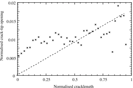
Figure 8 shows the increasing crack tip width as the crack is growing. The scatter for longer cracks indicates a somewhat unstable development of the crack.
Discussion
The selfsimilarity of the growing pit emanate from the evolution law (9). It is worth noting that the specification (9) does not involve any length scale. This is in contrast with crack growth based on common crack growth criterions. These normally add a length scale that serves as a reference for crack length. The selfsimilarity leads to a pit growth rate that is independent of the load. In perspective of the crack like pits that is observed for σ∞ = Eεf and
a) b) ε<εf ε=εf a ε>εf 2ρ ε=εf a
FIGURE 3. a) Typical pit for small remote loads, b) pit tip. The angle between the pit surfaces is α = ρ/a
assumed to appear for σ∞ ≥ Eεf, one note that the width of the crack-tip, however small, still
remains proportional to the crack length. This guarantees that the local load in the vicinity of the crack-tip remain constant.
This provide a possibility to estimate the threshold stress for real cracks such as the one shown in Fig. 1. The information provided with the figure is that the crack length a is around 7 mm and the crack tip radius ρ is around 5 µm (Lagerström [12]). Following (13) this tell us that the remote strain is only around 0.1 of the threshold strain. A perhaps better estimate is provided by the numerical calculation. The suggestion is that (13) is replaced with ρ/a = 0.01
€
ˆ
σ ∞2. Thus, the remote strain should be around 0.5 of the threshold strain.
Conclusions
In the examined model for corrosive dissolution controlled by a linear relation between surface strain and dissolution rate, the failure strain of a so called passivating film a threshold strain for failure play an important role.
The model leads to surface instability and formation of a crack like pit if the remote strain is the same as the threshold strain. The pit is observed to grow while preserving its over all shape. This selfsimilar growth imply that the crack tip speed is constant and independent of the remote load and crack length.
The result offers a possibility to determine the threshold strain by observation of the crack geometry. The ratio between the remote strain and the threshold strain is proportional to the ratio between the crack tip width and the crack length. The analysis revealed an unexplained discrepancy between the proportionality factor as determined from an approximate analyses and a finite element simulation.
References
1 . Bergman, M., Brickstad, M., Nilsson, F. A procedure for estimation of pipe break probabilities due to IGSCC. International Journal of Pressure Vessels and Piping, 74(3), pp. 239-248, 1997.
2. Roberge, P.R. Handbook of Corrosion Engineering. McGraw-Hill, New York, 2000.
εtip εf Γ 0 (π/2)ρ Γ ρ
FIGURE 4. Strain versus distance Γ along the notch tip surface. The strain is εf exactly
3. Parkins, R.N. Current understanding of stress-corrosion cracking. Journal of Metals, 44(12), pp. 12-19, 1992.
4. Turnbull, A. Modelling of environment assisted cracking. Corrosion Science, 34(6), pp. 921-960, 1993.
5. Kussmaul, K., Blind, D., Läpple, V. New observations on the crack growth rate of low alloy nuclear grade ferritic steels under constant active load in oxygenated high-temperature water. Nuclear Engineering & Design, 168(1-3), pp. 53-75, 1997.
-0.375 -0.25 -0.125 0 0.125 0.25 0.375 0 0.25 0.5 0.75 1 x/a y/a crack tip crack mouth body edge -0.06 -0.04 -0.02 0 0.02 0.04 0.06 -0.15 -0.1 -0.05 0 0.05 x/a-1 y/a crack surface body crack
FIGURE 6. a) Crack shape for
€
ˆ
σ ∞ = 1. b) near tip region showing a somewhat unstable development of the shape.
6. Heldt, J., Seifert, H.P. Stress corrosion cracking of low-alloy, reactor-pressure-vessel steels in oxygenated, high-temperature water. Nuclear Engineering & Design, 206(1), pp. 57-89, 2001.
7 . Jivkov, A.P. and Ståhle, P., Strain-driven corrosion crack growth. A pilot study of intergranular stress corrosion cracking. Engineering Fracture Mechanics, 69(18), pp. 2095-2111, 2002.
8. Jivkov, A.P. Evolution of fatigue crack corrosion from surface irregularities. Theoretical & Applied Fracture Mechanics, 40(1), pp. 45-54, 2003.
9. Tada, H., Paris, P.C., Irwin, G.R. The stress analysis of cracks handbook, 3d Ed. ASME Pres: New York, 2000.
10. ABAQUS User’s Manual, Version 6.3, Hibbitt, Karlsson & Sorensen Inc., 2002.
11. Jivkov, A.P., 2000. DIGITAL MATERIA - a finite strain based finite element program. Research report MUMAT2000:2, Malmö University Materials Science, Malmö, Sweden. 12. Lagerström, J. Private communication, 2003.
0 0.005 0.01 0.015 0.02 0 0.25 0.5 0.75 1 Normalised c rack-tip opening Normalised cracklength
FIGURE 8. Crack tip width versus crack length, for different crack lengths, normalized with largest computed crack lentgth, a.