Faculty of Technology and Social science Computer Science
Master thesis 15 credits
Forming Emergent Configurations in Smart Office IoT
Systems
Formandet av Emergent Configurations i Smarta kontors IoT Systems
Irengård Gullstrand, Simon
Wahlfrid, Jonas
Degree: One-Year Master 60 credits Main field: Computer Science
Program: Computer Science, Master’s Pro-gramme (One-Year)
Date of final seminar: 2017-05-30
Supervisor: Romina Spalazzese Co-supervisor: Fahed Alkhabbas
Other analysts:
Abstract
In this thesis, we examine how Emergent Configurations are formed to manage Things and People for the purpose of achieving the user’s goal of repairing a coffee machine in the dynamic environment of a smart office. We develop an architecture in the form of requirement and design artifacts as well as a realization of the Goal Manager component in the Emergent Configuration Manager which is responsible for the forming of Emergent Configurations, using the novel Emergent Configuration IoT system engineering approach. To demonstrate the capability of the realization we developed multiple case scenarios which correspond to the context dynamicity of a smart office environment. The results of this study introduce an architecture for the Goal Manager component and demonstrate that the novel engineering approach, Emergent Configuration, is a feasible way of managing IoT systems in the smart office category.
Keywords— Emergent Configurations, Internet of Things, Context-awareness, Self-adaptability, Smart Office, Augmented Reality, Maintenance
Popular Science Summary
Internet of Things is a growing trend that aims to connect everything that can benefit from being connected to the internet by providing new services and increasing the efficiency of those Things. The Smart Office is an example of one area where the Internet of Things concept can be applied and is popular because of the immediate advantages it brings by having devices connected. Even though there are numerous advantages connecting devices to the internet, there are also many challenges that need to be dealt with at all levels.
We use the novel approach Emergent Configurations to try to address the issues IoT sys-tems are facing. Emergent Configurations is an approach for how to engineer IoT syssys-tems, where multiple connected devices including their functionalities and services collaborate temporarily to achieve a common goal. Recently, researchers have introduced an abstract architecture describing how Emergent Configurations could be implemented to carry out its task. The main task of the Emergent Configurations is to be part of an IoT system and handle its involved Things and people by utilizing techniques like context-awareness and self-adaptability.
In this Master thesis we refine the abstract Emergent Configuration architecture and realize a part of the architecture in the context of a number of real-life scenarios. We continue to focus on the Goal Manager component, which is responsible for planning a course of action through which the collaborating users and devices can achieve a goal. Then we divide the Goal Manager up into a number of sub-components with the aim of introducing a general architecture for the component. Additionally we introduce a technique for interpreting goals, which is one of the most important responsibilities of the Goal Manager. We hope and aim for our contributions towards the abstract architecture of the Emergent Configurations to be used as a basis for engineering IoT systems with the Emergent Configurations approach in the future.
Acknowledgement
This study is part of a preliminary to a larger research project called Emergent Configu-rations of Connected Systems (ECOS) conducted at Malmö University within Internet of Things and People Research Center (IoTaP).
We would like to take the opportunity to thank our supervisor Romina Spalazzese and co-supervisor Fahed Alkhabbas for all the advice and guidance throughout the process of writing our master thesis.
Contents
1 Introduction 1
1.1 Purpose & Motivation . . . 2
1.2 Research scope . . . 3
1.3 Research question . . . 3
1.4 Research process . . . 3
2 Research Methodology 5 2.1 Design Science . . . 5
2.1.1 Alternative research methods . . . 5
2.1.2 Architectural view model . . . 5
2.1.3 Evaluation of requirements and design artifacts . . . 6
3 Related work 8 3.1 Smart offices . . . 8
3.2 Self-adaptive system . . . 8
3.2.1 Adaption management system . . . 8
3.3 Context . . . 9
3.3.1 Context-aware system . . . 9
3.3.2 Context management system . . . 11
3.4 Architecture for Emergent Configurations . . . 11
3.5 Augmented Reality . . . 12
3.6 Guided Maintenance Systems . . . 12
3.6.1 Elevator maintenance using Augmented Reality with the HoloLens . 12 3.6.2 Replacing an HDD in a Laptop . . . 14
3.6.3 Microsoft HoloLens . . . 14
3.6.4 Automated repair dispatcher . . . 16
3.7 Summary & Perspectives . . . 17
4 Realizing Emergent Configurations in Smart offices 19 4.1 Two coffee machine scenarios based on dynamic context . . . 19
4.1.1 Berit scenario . . . 19
4.1.2 Gunnar scenario . . . 19
4.2 Abstract architecture of Emergent Configurations within the coffee machine scenarios . . . 20
4.2.1 Logical view . . . 20
4.2.2 Forming of Emergent Configurations to achieve goals . . . 21
4.2.3 Manage Emergent Configurations to achieve goals . . . 22
4.2.4 Internal components of the ECM . . . 23
5 Refining the design of Emergent Configurations 26 5.1 Use Cases on coffee machine scenarios . . . 28
5.1.1 Actor descriptions . . . 28
5.2 Realization of the Goal Manager . . . 32
5.2.1 Software . . . 32
5.2.3 Functionalities of the realization . . . 33 5.2.4 Responsibility of the classes . . . 37 5.3 Summary & Perspectives . . . 41 6 Refining the Goal Manager component 42 6.1 Goal Manager Architecture . . . 42 6.2 Goal interpretation technique . . . 43
7 Discussion 45
7.1 Limitations & Threats to validity . . . 47 7.2 Recommendations . . . 48
8 Conclusion & Future work 51
8.1 Research question revisited . . . 51 8.2 Future work . . . 51
1
Introduction
Since the dawn of the Internet, the way we live our lives has changed drastically, enabling interaction between people in both professional and social life on a whole new virtual level [31]. There is currently a growing trend known as the Internet of Things (IoT) to connect everything that can benefit from being connected to the internet to provide new services and increase the efficiency [5]. The trend can be explained by the vision “Anytime, any-where, anymedia” which has for a long time been the driving force for the advances in communication technologies. This vision has made the technology more affordable and ubiquitous and therefore allowing easier connectivity [4, 31]. Cisco and Ericsson estimated that by 2022, 29 billion devices will be connected to the internet and this estimated num-ber is predicted to grow by 2030 when 5G is established [16]. “The Internet-of-Things has the potential to change the world, just as the Internet did. Maybe even more so.” [4]. Some areas which would benefit from the IoT innovation are e.g. smart office, smart living, energy, transportation, health, city, and industry. Even though there are numerous advantages of moving towards connecting many more devices to the internet, there is also a downside filled with challenges that need to be dealt with at all levels. Heterogene-ity, adaptabilHeterogene-ity, interoperabilHeterogene-ity, automation, middleware and reusability are examples of important aspects that need to be taken into consideration both at design time and at runtime [11, 17, 23]. A novel approach to try to address the mentioned issues IoT systems are facing is the Emergent Configurations (ECs). ECs is an approach for how to engineer IoT systems, where multiple connected Things/devices including their functionalities and services that collaborate temporarily with the focus on achieving a common goal. Kevin Ashton coined the term Internet of Things in 1999 [4]. The term means a network con-sisting of connected things. Things are heterogeneous, distributed and sometimes mobile; e.g. they could be: devices, vehicles, buildings, appliances, and clothes. These things are embedded with sensors, software, electronics and connectivity that enables these things to collect and exchange data [11, 17, 23]. Before the term IoT was introduced, most data on the Internet was collected and stored by humans manually. It was collected from de-vices in the real world, e.g. measurements from a temperature sensor. Data automation is desirable because people have limited time, attention span and accuracy level. By con-necting things that have environmental sensors to a network, this type of data collection and storage can be automated. Also, the sensors can collaborate and interact with each other to e.g. refine and maximize the accuracy of the output data. Connected things can, for instance, notify users when it is in need of being replaced or repaired. They could allow the users to track and count anything if the computers knew everything there was to know about things. This would result in reduced waste, loss and cost in that area [4], and also improving our way of living and working if e.g. the areas smart home and smart office are targeted. But with all these great advantages there is also a set of challenges that needs to be handled and figured out. Some examples of the aspects that need to be taken into account both at design time and at runtime are: Heterogeneity, adaptability, reusability, interoperability, data mining, security, abstraction, separation of concerns, automation, privacy, middle-ware and architectures. To properly addressing design and runtime man-agement of an IoT system it means that it is needed to provide solutions to several key issues in the IoT field, but because of limitations we will in this thesis focus only on the heterogeneity management in those systems.
As mentioned in the acknowledgment section, this thesis is a preliminary to a larger research project called Emergent Configurations of Connected Systems (ECOS) conducted at Malmö University within Internet of Things and People Research Center (IoTaP). Be-cause of this to try to deal with the issues IoT systems are facing we decided to examine the Emergent Configurations (ECs), which is a basis for a novel approach to engineering IoT systems. Ciccozzi and Spalazzese in their paper about Supporting the IoT with Model-Driven Engineering uses a term called Emergent Configuration. It is defined as “Within the IoT, we call Emergent Configuration as a set of Things with their functionalities and services that connect and cooperate temporarily to achieve a goal” [11]. IoT applications run in continuously changing and unpredictable environments, and since it involves Things, it could be mobile devices which can become unreachable or new devices can be discovered during runtime. Therefore, the design of ECs should be resilient and be able to respond to dynamic changes in the environment and context while maintaining the achievement of the goal. In other words, ECs should have the capability to self-adapt in response to the unpredictable runtime changes. EC is explained further by introducing related con-cepts called; context-awareness and self-adaptive system in section 3. Context-awareness in a system can be explained as a system gathering data by sensors from the constantly changing surrounding environment.
1.1 Purpose & Motivation
The purpose of this study is to demonstrate how ECs can be implemented and formed in a smart office environment to be able to manage and adapt to the contextual changes with the aim of achieving a goal of repairing a coffee machine. Various useful ways in which ECs can manage varying context and heterogeneity in an IoT system applicable to a smart office environment are researched and established, including value adding aspects to appliance maintenance personnel and office personnel alike. As there is a constantly changing context in a smart office environment and with the involvement of users in the loop the variables to consider becomes complex. To manage this complexity, we developed requirement and design artifacts based on the IoT system engineering approach EC and then realized the Goal Manager component of the Emergent Configuration Manager (ECM), while applied in a fictive smart office IoT system involving a Coffee machine. The requirements and design artifacts are developed by first conducting a literature review for the purpose of gaining insight and understanding of the state-of-the-art regarding the chosen smart office environment, the EC concept, and its related fields which are all explained in details in section 3. The concept of both IoT and ECs are explained further in the following sub-sections.
To examine how ECs can be formed could handle the ever changing environment and since it is a novel approach we realized the Goal Manager component, the decision is further explained in section 3.7. The Goal Manager is the component in the ECM in which is responsible for taking as input (data from sensors) a variety of context variables including Things and People as well as interpret the identified goal of the EC during the forming phase. The interpretation process of the goal will aid the Goal Manager in deciding the best approach to how to achieve the goal in the best way. All of this is explained in detail in section 4.2. To further simulate the concept of ECs and to enable the Goal Managers functionalities in the smart office environment we developed case scenarios as well as a
refined architecture in the form of requirements and design artifacts based on an abstract architecture proposed by [2] and further explained in section 4.2. This is explained in detail in section 5. With the new insights gathered from this research we also introduce an architecture for the sub-components of the Goal Manager, and last, but not least we also introduce a technique for interpreting goals.
1.2 Research scope
To narrow down the study, we focused on the smart office category of IoT environments, more specifically an appliance; the coffee machine, with the goal of repairing the machine. For the purpose of answering the research question described in section 1.3, the current state-of-the-art in the area is being investigated. With the learned knowledge, we developed an architecture in the form of requirement and design artifacts as well as a realization of the Goal Manager component in the ECM using the novel EC engineering approach for IoT systems. For the practical part of the study to be feasible, the design science method is limited to investigating two case scenarios of an IoT system, and only one component of the ECM realized. To further limit our work, we focus on how ECs are formed to manage Things and People to achieve the user goal of repairing a coffee machine in the dynamic environment of a smart office.
1.3 Research question
Based on the expressed purpose and motivation in section 1.1 for this research, the following hypothesis & research question were raised:
Hypothesis: The abstract architecture provided for Emergent Configurations can be refined towards a realization.
RQ1. How can an architecture be designed to allow Emergent Configurations to be auto-matically formed based on the goal and the dynamic context in a smart office?
1.4 Research process
To achieve the main objective of this research and answer the research question, the fol-lowing research process has been taken illustrated in figure 1:
1. Study the literature about IoT, Smart offices, Context-awareness, Self-adaptiveness and Emergent Configurations.
2. Develop case scenarios with the aim of being able to answer the research question. 3. Develop requirement and design artifacts based on the case scenarios with the fictive
smart office IoT system involving the appliance; coffee machine.
4. Develop the Goal Manager component of the ECM to simulate the forming of ECs based on the case scenarios and artifacts.
5. Develop an architecture for the Goal Manager. 6. Develop a technique for how to interpret goals.
7. Draw conclusions from the research.
2
Research Methodology
In this section, the selected research methodology that is used in the process of answering the research question is discussed. The section starts with a brief overview of the chosen design science research method, followed by a discussion of the methods that are used for the development and evaluation of the artifacts produced in our research.
2.1 Design Science
In order to answer the research question, the design science method was chosen. March and Smith describe the design science process as build and evaluate [24]. In the build activity artifacts are developed, such as constructs, models, methods or realizations. We have utilized Hevner’s framework [35] for how to perform the research process of design science which focuses on developing innovative artifacts with the goal of extending the boundaries of human and organizational capabilities. Hevner et al. describes a framework for information systems research, see figure 2. In this framework development and evalu-ation of artifacts gets the business needs from the environment and applicable knowledge from the knowledge base iteratively. The environment consists of people, organizations and technology and the knowledge base rests on the scientific literature [35]. In this the-sis requirement and design artifacts for a fictive IoT system involving a coffee machine is developed. The artifacts were developed with the help of the design science research process model illustrated in figure 2 developed by [35]. The artifacts in this thesis have been developed iteratively in a series of small iterations and informally evaluated after each iteration to increase the quility of the end result. The development has led to requirements and design artifacts, described in section 4, and a realization of those artifacts in the form of an application written in Java, described in section 5.2.
2.1.1 Alternative research methods
An alternative research method that could have been used is a mix of quantitative and qualitative research. Where we could have developed a full-scale real world prototype of the IoT system. The results could have provided important insights and well-defined requirements on how to improve the prototype further. After being deployed it could be evaluated and provide more accurate results by conducting a survey in the form of a questionnaire e.g. could have been carried out along with observations on a user test to evaluate if the system is usable and works to the users liking. This approach is not feasible from a time view for us however since we would have to wait for the appliance to break down before we could measure and collect any real data. This is why we instead chose the design science approach to demonstrate the proposed solution as a small scale artifact of the requirements and design of the system, that could be a good start for a real world implementation. The implementation of the full-scale real world prototype is suggested as future work in section 8.2.
2.1.2 Architectural view model
The development process in this research utilizes the 4+1 architectural view model [22] illustrated in figure 3. The view model consists of four outer views; logical, development,
Figure 2: Information Systems Research Framework [35]
process, physical view and one central view; Scenarios or as it is also called use cases, which everything revolves around. We have realized the central Scenarios view by developing use cases (presented in section 5) and case scenarios (presented in section 4.1) to as mentioned revolve the rest of the development around. The development view uses a UML Component diagram and Package diagram to describe the components of the system illustrated in figure 17. The logical view is represented by class diagrams and state diagrams illustrated in figure 24 and in the Sequence diagram illustrated in appendix B. The Physical view is represented by the developed UML deployment diagram illustrated in figure 17. The process view is realized and described in section 5.2, and illustrated in the activity diagram 26.
2.1.3 Evaluation of requirements and design artifacts
The evaluation process aims to validate the artifacts developed with the EC engineering approach to tell if they are feasible in a fictive IoT system. To be able to validate the artifacts as well as answering the research question a realization of the Goal Manager component in the ECM is developed. The realization is a part of a fictive IoT system and aims to simulate the forming of ECs based on the case scenarios. In this fictive IoT system, there are several Things and people to consider as part of the context. The context can also vary and change as mentioned in the 3.3. To fully implement the realization we have taken multiple scenarios into account which translates into different contexts for each
Figure 3: 4+1 architectural view model [22]
scenario. The implementation aims to be able to handle the variations in the context. The requirements and design artifacts are a basis for how EC could be realized into a smart office environment and in turn what is developed in the realization.
3
Related work
This section aims to present the current state-of-the-art regarding IoT systems, context-awareness, and self-adaptive systems. Context-awareness will let the IoT system recognize changes in its runtime environment and be able to change its behavior. A Self-adaptive system in the IoT system can based on e.g. runtime issues in some device redirect the user to continue on another device. Followed by a summary and perspectives section to briefly summarize what we have learned from the literature.
3.1 Smart offices
A Smart office is simply a category of IoT applicability. A smart office is recognized from its predecessor the office space, where you would find devices like desktop computers and appliances like printers connected with a cable to a router for internet access. Contrary to this, a smart office is an office environment where you would find laptops, printers, smart heaters, smart window blinds, coffee machines, etc. which are all connected to a network and then usually also to the internet [12]. An example of a simple IoT appliance installed already today in many offices is the smart thermostat, which can determine when employees are present in certain rooms based on sensors and the employee’s calendars and then alter the levels of heating, lighting and other functions in the office accordingly.
3.2 Self-adaptive system
Self-adaptation is the distributed system’s ability to adjust and adapt its behavior as a response based on its perception of the surrounding context and the system itself, to fulfill its set of goals in an optimal way. It is worth to note that this is easier said than done since the surrounding context of IoT systems are extremely dynamic and continuously changing. Self-adaptation is of necessity because of the high demand in systems today for flexibility, configure-ability, resistance, energy-efficiency, self-optimization by adapting to changes that may occur in the operational context and the system requirements [13]. To be able to adapt to a context the system is required to be context-aware, more on this in the next section. E.g. a device that is connected to the system becomes unavailable as a result of connection issues or battery level etc, the self-adaptive system should be able to handle this issue by using related sensors data to keep on providing the desired result. As a last resort also be able to alert a repair crew to repair the device.
3.2.1 Adaption management system
These kind of scenarios mentioned in the previous section could be managed by an adaption controller which can be realized by the MAPE-K loop [13, 30]. The MAPE-K loop consists of a sequence of four activities: Monitor, Analyze, Plan and Execute illustrated in figure 4. By utilizing the MAPE-K loop in our IoT system, we can a) monitor changes in the context (more on the topic context in the next section). The changes could both be propagation in the goals of the user, and changes like newly discovered devices or the lose of those connected devices while the systems work towards achieving the goal. b) Analyses the effect in which the detected change had towards, in turn, satisfy the goal. c) Plan how to respond to the detected changes to satisfy the goal or potentially apply changes to the
EC subgoal model. d) Executes the plan by communicating the instructions to the right component of the system.
Figure 4: The MAPE-K loop
3.3 Context
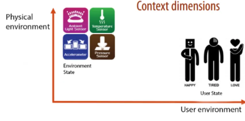
To better understand how context-awareness works we first need to define what context is. Schilit and Theimer who were first to introduce the term ‘context-aware’ defines context as location, identities of nearby people and objects and changes that occur to those objects [29]. There are several definitions of context in the literature available since there is no clear definition of context and it is also difficult to apply them as they are defined by example. Brown et al. mean that the constantly changing execution environment is the context [1]. But the environment is split into three categories, which is visualized in figure 5. There is the system environment itself with the available network capacity, connectivity, processor, devices accessible for user input and display. For the surrounding environment, there is the User environment, which is a location, a collection of nearby people and social situations. And there is the Physical environment which is e.g. the lighting and noise level [29]. Dey et al. mean that context can be the user’s physical, emotional, social or information state [15]. Because as a software developer we can not predict which aspects of a situation or environment is important, as it changes from situation to situation. In some case, the User environment may be important, while in another case it may be entirely insignificant. For this reason also Schilit et al. and Dey et al.’s definition becomes too fussy. A more developer focused definition for context is that any information that can be used to characterize the situation of an entity is context. Where an entity is a place, a person or an object that is to the interaction between a user and a system considered relevant, including the user and system themselves [1].
3.3.1 Context-aware system
In order to fulfill the characteristics of a self-adaptive system and to be able to satisfy a goal which in turn forms the ECs, the system also needs to be context-aware. A system is context-aware if it can extract and interpret context information from the execution
Figure 5: Context dimensions
context and has the ability to use it and adapt its functionality accordingly. Then perform an action based on the change in the context [9, 27]. It can also be described as the system’s perception of the context within the surrounding environment and the system itself. From the user perspective, it is a context- aware human-like service with minimal user effort to configure. Since people have different preferences, the system may need to reason about and adapt its behavior to also individual users accordingly [32]. The provisioned context information needs to be reliable and above all available when it is needed by the connected applications and systems. This demand is challenging for many reasons in many contexts as the information is produced from one source and that is the sensors. They can fail, or their network communication may get interrupted and disconnect or due to mobility they break, etc [21]. To supply this reliability a common approach is to use redundancy of context sources. With available redundant and always sources of context information [10] it brings the possibility to withstand failures of some context sources. This approach will not scale to a larger quantity of sensors though since it can be very wasteful as well as be demanding of resource usage [21]. One way to describe a context-aware systems architecture is through the Layered conceptual framework illustrated in figure 6 for context-aware systems by Baldauf [6]. It is called layered since there are five layers of the architecture. The first layer consists of different sensors. He emphasizes here that the word “sensor” does not only refer to sensors as hardware but also to all data sources that provide usable context information. The second layer is all about the retrieval of raw context data. It handles the required drivers for physical sensors and APIs for logical sensors that is needed. The preprocessing layer is responsible for reasoning and interpreting the contextual information from the data to only pass through the data that is needed for the application. Also if there are several sensors that are gathering information that will need to be combined in order to make any use of it is processed in this layer. This layer is not always necessary if these things are not needed or can be accomplished already on the previous layer. The fourth layer, Storage/ Management, does as the name suggests, Store the data in an organized way and offers it to the application through a public interface. The fifth layer is the application which the end user interacts with. Here is the logic for reactions and management to different contextual events implemented. An example of context logic in the application is the display on most smartphones/phablets: when a light sensor detects changing light from the environment, the brightness of the display will change accordingly.
Figure 6: Layered conceptual framework for context-aware systems by Baldauf [6]
3.3.2 Context management system
To solve the reliability issue in a better sense, and provide efficient management of resources it is necessary to bring autonomy into the systems. The autonomy will focus on areas like gathering, managing, pre-processing and provisioning context information. This kind of systems is commonly termed context management systems (CMS). An objective of the autonomic computing is the notion that the systems should be able to perform self-management, this can be obtained by allowing collaboration between the systems. Self-management means that the system can self-configure, re-configure, self-heal, self-protect and self-optimize. The pros that autonomy will bring for the CMS will allow e.g. dynamic and automatic configuration of context information sources, an easier and better way of monitoring the system to counter failures quickly and an extended ability to use the sensors [21]. Another key motivation for utilizing a CMS is to be able to separate the context-aware system itself from the context data. These systems can be implemented as a separate service with sensors or as a middle-ware between the core systems software functionalities and the context which the system is utilized in [36]. The CMS takes into consideration the data inputs from hardware sensors that are constantly reading values from the context and saving it into a database for storage and easy access. The CMS can also make decisions based on potential changes in the data that can trigger the corresponding parts of the core system to achieve a desired goal [14, 36]. Since the CMS has all the data from the context stored, it also handles the requests from users and other services so that they do not have to manage the database with all of the data themselves. The CMS also handles the related access privileges to the context data to ensure the integrity and privacy of the data and the owners of the data [34, 36].
3.4 Architecture for Emergent Configurations
In [2] a initial architecture for ECs and a goal-oriented approach is illustrated with the help of a case scenario. More specifically how the EC is formed, managed and finally achieves its main goal in the context of a smart office meeting room with several con-nected Things. They have examined several approaches to engineering IoT systems e.g. The Service-Oriented Architecture where the goal is to obtain collaboration between and interoperability among IoT heterogeneous objects [26]. However, the architecture does not seem to cover user integration with the aspect of self-adaptation in the case of runtime
changes to the user goals. This is one of the reasons why the concept of ECs as a basis for a novel approach for engineering IoT systems is presented. Which will overcome the shortcomings of existing approaches while also at the same time provide answers towards the needs of IoT systems. An EC is defined as a set of Things with their functionalities and services that connect and cooperate temporarily to achieve a goal. In their paper [2], they have concluded that when realizing complex IoT-based systems, the ECs could be a very valuable aid. In our thesis, we also want to use the vision of ECs as a basis for a novel approach for engineering IoT systems and examine its feasible by implementing the concept into a fictive smart office system. The research in this paper point towards the Goal Manager component in the ECM to be a fitting component to realize. As the component is responsible for the forming of ECs and to provide reactions to the contextual variations in the environment.
3.5 Augmented Reality
Augmented Reality is becoming more and more popular both as a presentation and in-teraction means [28]. An augmentation of the real world with virtual objects are called Augmented Reality (AR), contrary to Virtual Reality which is about creating an entire virtual world. In an AR system, the virtual information is added on top of the real world-view. All the human senses may be involved, but the virtual information and objects are normally generated by a computer, and the user views the combined image [25]. By mix-ing a virtual view with real life, the user can get additional visual contextual information. E.g. an application domain is to display a manual of the object that is to be assembled or disassembled together with the real world view. This ensures that the user does not need to switch between a paper manual and the assembly work, and can, therefore, focus on both at the same time [18]. Fundamentally the user is able to interact with the virtual world in some way, an example of this could be that the user can navigate by moving and looking around in the virtual world. Also to manipulate virtual objects, by moving them or changing their state in some way. For the interaction to work and for the users experience to feel as natural as possible generally the device that is responsible for the Aug-mented Reality has some kind of gesture tracking device impleAug-mented. This is to be able to track the user’s hand gestures, the tracking device recognizes preprogrammed gestures and invokes different functionalities based on the gesture and where the user is aiming the device. There is also in some cases eye tracking as well which makes the experience even more natural for the user when interacting and navigating in the virtual world [12]. AR is an excellent choice regarding guidance in maintenance activities since it has the potential to bring clear instructions to a novice in distraction free and pedagogical way [28].
3.6 Guided Maintenance Systems
3.6.1 Elevator maintenance using Augmented Reality with the HoloLens This related work is about an IoT system that is focused mainly on utilizing AR to achieve their set of goals, which is to make the life of the elevator repairers easier and better. It is relevant to our work because it shows that AR could be utilized to maintain a machine. The company thyssenkrupp utilizes the technology of Microsoft HoloLens to give 24 000 elevator service technicians access to Augmented Reality maintenance guiding and training
[20]. The service technicians can visualize the elevator and its components illustrated in figure 7, technical information, service logs, events, and alarms ahead of a job, which makes it possible to train personnel, plan work and know which spare parts to bring in advance.
Figure 7: Visualization of the elevator and its components in Augmented Reality [20]
When working with the elevator, the service technicians can get hands-free access to Augmented Reality maintenance guiding through the HoloLens headgear. It will present to the service technicians a 3D representation of parts, task orders, safety alerts, service logs, events and alarms, visualized in figure 8. This new way of hands-free interaction can be compared to the traditional approach where the service technicians had to bring a laptop to gain access to the same information.
Figure 8: Augmented Reality maintenance guide [20]
Skype on HoloLens can be used by the technicians to make a video call to an expert for further assistance if needed, visualized in figure 9. The expert can remotely highlight the part of the system that is in need e.g. to be replaced, and it will be presented visually to the technicians in Augmented Reality on top of the actual system. This brings ease for the technicians to quickly recognize where the problem is.
Figure 9: Skype on HoloLens [20]
up to four times faster than before by using the HoloLens technology [20]. The HoloLens implementation gets events and alarms from elevators that are connected to thyssenkrupps MAX system, that is built with Microsoft’s IoT management system Azure. By utilizing Microsoft’s Azure IoT Suite [17], elevator data e.g. motor temperature, shaft alignment, cab speed and door functioning, are obtained and reported back to the management system for analysis, monitoring, and predictions. This is for future maintenance before they occur by flagging the need to replace components and systems before the end of their life cycle etc. The technicians also have easier access to elevator events and alarms [17, 20].
3.6.2 Replacing an HDD in a Laptop
Related to the field of AR there has recently been an experimental user study performed on an office appliance to evaluate applications for AR [28]. In this study, the participants were given a task to replace a hard disk drive (HDD) in a netbook, and the completion times and errors between using AR and paper-based manuals were compared. In the first cycle of tests, the task of switching an HDD in a laptop was carried out by ten people, who were used to working with computers. The time it took to complete the task was about twice as long with the AR-based solution compared to a paper manual. However, there occurred only three mistakes with AR compared to ten with the paper manual. The same test was repeated with twelve participants who were not used to working with computers. In this group, it took an average of ten minutes with AR and eleven minutes with a paper manual. The standard deviation with AR was one and a half minute and two and a half minutes with a paper manual. By using AR, the number of mistakes decreased to one-third compared to the paper manual. The study concluded that the lower the skill level, the greater the benefits of using AR solutions [28].
3.6.3 Microsoft HoloLens
Microsoft HoloLens is a battery powered wireless Augmented Reality Windows 10 com-puter, that can show the user three-dimensional virtual objects [33]. The three-dimensional
virtual objects are anchored in the real-world surrounding. The user can walk around the three-dimensional virtual objects, viewing them from every angle and interact with them. The accompanying controller illustrated in figure 10 has five buttons: a power button, +/- buttons for sound volume, and +/- buttons for contrast for the Augmented Reality lenses. The user input is done with gestures and voice commands. Voice commands are picked up by a built-in or external microphone connected to the 3,5 mm connector. It is also possible to use a handheld device called the Clicker, see figure 10. The Clicker has a button and an accelerometer that is used for orientation sensing. A wireless game controller or a cordless mouse can also be used as input devices if desired.
Figure 10: Clicker [19]
The HoloLens has support for data communication via Wi-Fi, Bluetooth, and USB. There are three different processors in the HoloLens: a 64-bit central processing unit (CPU), a graphics-processing unit (GPU), and a holographic processing unit (HPU). The Inertial Measurement Unit (IMU) has an accelerometer, a gyroscope, and a magnetometer. These sensors track where the user’s head is and how it is moving.
The HoloLens has two visible and infrared wavelength cameras on the right side and two on the left side. The infrared wavelength is used together with the four infrared diode light sources. The infrared lighting makes the device less dependent on external lighting. Since the cameras are mounted in a pair and with an offset, a stereoscopic image is captured. The stereoscopic image is used to calculate a 3D mesh/map of the room. The 3D mesh/map of the room makes it possible to anchor the three-dimensional virtual objects in the real world. In addition to the four visible and infrared wavelength cameras, an infrared camera facing straight is mounted in the center. The infrared camera is used together with an infrared laser projector to scan objects, to measure the distances to them. There is also a camera in the center that can take videos or still images, see figure 11.
Figure 11: HoloLens hardware architecture [19]
The IMU sensors that track head movement is fused with the three-dimensional per-ception of the real world from the cameras. The three-dimensional information makes it
possible to anchor the three-dimensional virtual objects in the real world. The virtual objects are rendered from the right perspective, size and distance from the user. The user can walk around a virtual object and see all its sides.
The HoloLens has Left and right loudspeakers, see the red plastics in figure 11. There is also a 3,5 mm aux connector for external headphones.
It also has transparent lenses so the user can see right through them. The lenses/waveguiders have an array of invisible grooves that directs the light from the left and right microdis-plays into the user’s eyes so that an image is displayed, see figure 12. The user sees virtual objects in the room as they were in the real world [33].
Figure 12: Lenses /waveguides and microdisplays [19]
3.6.4 Automated repair dispatcher
In this paper [3], the authors propose a context-aware semi-automated repair task dis-patcher for IoT systems. The disdis-patcher is implemented for the purpose of fault manage-ment in an electric power distribution network. The motivation for the implemanage-mentation is to solve the issues faced in the following scenario: A human dispatcher assigns the repair tasks to a specific repairer when the system notifies the human in the form of alarms. The human factor, which involves multiple manual actions may cause bottlenecks and delays in the process of dispatching the repair tasks to a repairer. Because humans are a limitation since we make mistakes and we do not always have all the facts, it is better to automate the assigning repair task process.
The implemented system has the following components: The first component is a receiver which is a human alarm operator whose only job is to submit the repair tasks via the receiver user interface to the system. The system then processes the repair task further in the following component. The next component is the processing engine which evaluates the repair task in order to select the most suitable repairers for the specific repair task. The evaluation process includes contextual information. Such are the job title, which department the repairer works at, the current location and availability of the repairer. The third component is called the match filter, it is used to further filter out repairers that are less suitable for the specific repair task after the evaluation process in the previous component is finished. The filter is basically another iteration of the evaluation process, focused this time on: what job title and department the repairer has, the availability of the
repairer and lastly the repairers related experiences to the specific repair task. The fourth component is Shortest Path Calculator, this component calculates the distance between the selected repairers and the repair task location. The fifth component is a mobile Application for Android, which is firstly used in the previous components for retrieving the repairer’s location from the smartphone’s GPS receiver and also the repairer’s availability status. The repairer uses the application as a user interface to accepting repair tasks that are assigned to him and also to navigate to the repair location with the help of a map in the application. The conclusion of the case study they did in the paper showed that their implementation compared with a fully manual dispatcher approach, an improvement amounting to repaired faults, reduction in the duration of finishing repair tasks, increased user satisfaction and reduced overall costs for the company [3].
3.7 Summary & Perspectives
An important aim of our study is to show that ECs are applicable in the smart office category, this is an example of an environment with the purpose of being able to generalize results since it is similar to many other applicable areas for within IoT field, E.g. smart homes. Our related work starts with exploring the environment of smart offices from the angle of an IoT system and concludes that the contextual dynamics can vary. But to see the system collaborate and have the same goal an approach could be to form ECs to manage the involved objects and people based on context changes. As IoT systems are quite complex and dynamic, the context changes all the time. The concept of a dynamic, connected smart office is being adopted widely since it adds many significant advantages to the office personnel, etc. But as mentioned in the introduction to this research it also comes with challenges. We believe the EC to be a great implementation in a smart office IoT system to assist the employees. As explored in [2] the EC could be very helpful as an aid in a simple everyday task as presenting presentation slides in a meeting. Similarly, we have studied how ECs could be formed to assist in a situation where there occurs an error in an appliance and how to provide maintenance instructions to a suitable repairer. But for the ECs to be able to handle such complex contextual changes, related areas of EC was reviewed. We started by examining what context really is, to learn even more about the concepts of EC, we examined Context management systems and the autonomy it aims to bring into the picture. The EC aims not only to be able to manage the context but at the same time adapt to changes during runtime, and therefore we saw the need to gain knowledge also in the area of Self-adaptive systems and how Adaption management systems work. Before most, we wanted to further understand the MAPE-K loop in which is envisioned to be utilized by the ECM [2]. Further regarding how it is utilized in our development and the EC is explained in section 3.2.1. Section 3.4 contains a review of a paper proposing an architecture for ECs and a developed approach for how EC could be implemented. The paper describes with the help of a case scenario with the goal of aiding the user in the process of presenting a presentation in a smart office environment. Also how the implementation of the EC, in this case, could be realized.
In this thesis, we have developed an architecture in the form of requirements and design artifacts to enable multiple case scenarios with the goal of repairing a coffee machine in the environment of a smart office. To expand the understanding before developing our fictive smart office environment and the case scenarios we researched the related domains
of Maintenance Systems, Automatic repair dispatching, AR and the HoloLens. From this, we could conclude that AR is a good choice for a beginner repairer to use to repair an appliance like a coffee machine as it allows for a more pedagogic way of following the repair instructions. In combination with the Microsoft HoloLens which is a head mounted display enabling AR based repair instructions will allow the user a hands-free repair process. And the Automatic repair dispatcher was researched because we wanted to learn how a system can dispatch (provide) the user with the necessary information and guidance to be able to achieve the goal of the EC, which is to repair the coffee machine. We have additionally to be able to demonstrate the forming of ECs in a smart office environment and to achieve the goals in our developed case scenarios realized the Goal Manager component of the ECM. Where the goal of the EC, in this case, is an error in a coffee machine and the process of repairing it. The Goal Manager component was chosen since it is responsible for the forming of ECs by examining the goal and draw based on context information a decision to how to in the best way utilize the surrounding context (objects and people) to address the goal of repairing the coffee machine. The realized realization is capable of functionalities which correspond with the envisioned Goal Manager component responsibilities [2] which also corresponds with the case scenarios we created for the fictive smart office environment. The development process of the Goal Manager was done with the help of the knowledge learned from the previously mentioned related fields researched. Then in turn with the insights from the development process, we introduce an architecture of sub-components for the Goal Manager as well as develop a Goal interpretation technique.
4
Realizing Emergent Configurations in Smart offices
The main objective of this research is to examine and learn how ECs can be formed in the case of an error occurring in a smart office appliance to achieve the user goals of repairing the error in that machine. We want to utilize adaptivity and context-awareness of the ECs to simulate the forming of an EC based on the case scenarios. We have with the new insights, based on the abstract architecture proposed a refined architecture in the form of requirement and design artifacts as well as a realization of the Goal Manager component in the ECM. To do this we utilize the 4+1 view model further described in section 2.1.2 and illustrated in figure 3.
4.1 Two coffee machine scenarios based on dynamic context
The scenarios explore the event of a coffee machine breaking down and how the ECM is assigning the task to a suitable repairer based on location, expertise and experience level. How the ECs determines what device based on location, instruction type capability and what type of instructions fits the selected repairer best to be then able to provide it to the repairer. The scenarios corresponding context variables are displayed in table 1 and 2.
4.1.1 Berit scenario
Berit felt a bit tired in her chair in the office and decided to head to the break room for a cup of coffee. Within this room, there is a coffee machine, a HoloLens, and a phablet since Berit brought one with her, and all of them are connected to the network. The ECM has detected an error in the coffee machine, and the goal to repair the error is indicated, and an EC has been formed, illustrated in figure 14. The ECM automatically diagnosed the machine to determine the gravity of the error, and an error message is displayed on the machine’s display. When Berit arrives in the break room, the ECM recognizes her level of expertise through an NFC tag reader. In this case, the ECM decides to ask her for help in order to repair the machine since her expertise level is recognized as “novice” and this meets the requirements for the current repair task. She accepts the task to repair the machine by using her tag with the tag reader nearby the coffee machine. Once the context is defined, nearby devices which are suitable for the repair task are highlighted to Berit through the coffee machine’s display. Berit gets advised through the coffee machines display to put on the HoloLens. This is because it is the most suitable device since the AR instructions are easiest to follow on the HoloLens as it is a hands-free head-mounted display. Then she is advised to scan the QR code on the coffee machine display. The QR code provides one-time login with a link to the AR maintenance guidance instructions in the necessary level to fit the device and the user. Then once the AR maintenance guidance is fetched, Berit follow the AR steps on the HoloLens to repair the coffee machine.
4.1.2 Gunnar scenario
The office is quiet in the evening and there is barely anyone left in the building. In one of the break rooms, a coffee machine has an error occurring. The ECM gets notified about the error and acts on it by forming an EC. The error is analyzed and concluded that it is so severe that the required expertise level needs to be an expert. Since it is after office
Context categories Context variables
Goal Repair the coffee machine error using AR
Location Inside break room (Close to the Appliance with error) Repairers Expertise level - Novice, Experience level - Newbie
Things Appliance - Coffee machine, Resources - NFC Tag & NFC Tag reader, Device - HoloLens & Phablet
Table 1: Context variables in scenario one
hours a night shift service provider is contacted and a maintenance ticket is submitted by the EC. When Gunnar arrives into the break room and identifies himself through an NFC tag reader, the ECM recognizes his expertise level as "expert" and the currently available devices in the break room. The devices are a phablet and a PC. The ECM goes ahead to show the error information on the coffee machines display as well as push the text based maintenance guidance instructions to his PC. This decision was made since Gunnar is an expert repairer and the most common device of choice is a PC. Gunnar follows the instruction steps and successfully repairs the coffee machine.
Context categories Context variables
Goal Repair the coffee machine error using Text
Location Inside break room (Close to the Appliance with error) Repairers Expertise level - Expert
Things Appliance - Coffee machine, Resources - NFC Tag & NFC Tag reader, Device - PC & Phablet
Table 2: Context variables in scenario two
4.2 Abstract architecture of Emergent Configurations within the coffee machine scenarios
In this section, the ECs logical view and the process of forming and managing ECs are explained using the coffee machine error case. The following sections are three sub-parts of ECs in the smart office with a coffee machine error scenario, where the first one; ECs logical view introduces the theory of ECs on a high abstract level. The second describes how ECs are formed related to our scenarios when an error is reported by the appliance. The third one addresses the process of how the EC is also involved when the EC manages the IoT system in the scenarios with the aim of achieving the goal of repairing the appliance with an error. The last part looks at the envisioned internal components of the ECM in relation with the related work.
4.2.1 Logical view
For the purpose of a logical representation of the EC this description is kept simple (The EC can be implemented both in a centralized and decentralized way). The EC can be broken down into three components on the logical layer, also illustrated in figure 13, which collaborate, interact and coordinates to allow the EC to be formed, operated and managed
[2]. The components are: (i) User Agent (UA) which is used by the user of the system to interact with the ECM at runtime to input his/her goals. (ii) Emergent Configuration Manager (ECM) which main focus is to satisfy the user’s goals by forming, operating and managing ECs. (iii) Device Manager (DM) has the task of keeping track of the connected devices, IoT things and objects with their functionalities in the environment of the IoT system. The DM continuously monitors and updates the ECM about the status of the devices, if they are newly discovered or if they become inaccessible because of connection loss or similar runtime changes. (iv) The set of devices in the IoT system, which connect and cooperate by command from the ECM for the purpose of realizing the EC. This is the Physical layer illustrated in figure 13. To be able to achieve the goal with higher quality external services are also available to integrate into the system.
Figure 13: Logical and physical layers of ECs
4.2.2 Forming of Emergent Configurations to achieve goals
The first process is the forming of the EC illustrated in the sequence diagram in figure 14. When a broken part is detected in an appliance, it is automatically detected and the error code is uploaded to the ECM. The ECM recognizes the error as the main EC goal and starts the process of forming an EC. The error code is then analyzed in the ECM to determine the lowest required expertise level for the repairer. This requirement is a subgoal of the EC. If the error is of a simple nature, the error will be reported to the office personnel to be handled quickly at the location of the appliance. An office personnel who has previous experience in maintaining the appliance would be preferred over someone who does not. If the error task is too difficult for a novice repairer (office personnel), it will be passed to the service provider and ideally also directly to a nearby expert repairer to
maintain the appliance as soon as possible. After the goal has been transformed into a concrete representation it can act on it. As a first step, a repair task is created for each acceptable expertise level with the necessary steps to repair the appliance and saved into the ECM’s knowledge base for easy fetching later. An important subgoal is to identify available IoT objects/services which fit into the context of the goal and the goals matches the provided functionalities. The vendors with the services are required to provide APIs for the EC to be able to utilize the functionalities. The ECM looks up external services and suggests relevant ones. An external service that could be used in combination with the system knowledge base is the Sigma Technology: DocFactory. The instructions and AR assets for the application could be stored here to be accessed later from the devices to be used. In this case, the demand on the device is that it is capable of running the AR maintenance application. Also, its position (location) should be nearby the appliance so that the office personnel has physical access to the device. Information about the nearby devices which are suitable are provided to the ECM by the DM. Then the ECM derives the EC subgoals. The next part aims to create atomic goals by decomposing the EC main goal and user inputted goals to subgoals (illustrated in figure 14). Atomic goals, in this case, is e.g. to determine who is suitable for the maintenance task, what devices are capable of running the AR application and also related contextual goals like setting the light level which could be achieved by Things. When the atomic goals are set, an order need to be defined to perform the subgoals. To do this the ECM relates the analyses of functionalities of the available objects/Things/services to determine how they can aid in the achieving of the goals. E.g. the schedule is checked before sending out notifications to nearby potential repairers. This type of action does not move the EC closer to achieving the main goal directly but it is a good example of subgoals that contribute to the quality of the main goal “Repair the coffee machine”. During runtime alternative ways to achieve the main goal are continuously updated as well illustrated in figure 15. If the goal, however, is not understood or there are no available Things to achieve all required atomic goals, the user agent is simply informed that the goal is not achievable in the current context. But if the main goal is achievable, the ECM forms an EC as explained previously with the derived subgoal model and starts the EC management phase to instruct Things to operate. E.g. nearby suitable devices with the AR application are highlighted to the repairer by the ECM automatically. The ECs design has to be able to adapt during runtime to context changes and be resilient since it operates in a dynamic and uncertain environment [13]. The constituents of the ECs are now in our case to clarify; the coffee machine, a HoloLens and a phablet in the IoT system that has been recognized to satisfy the requirements to achieve the main goal, also illustrated in figure 13.
4.2.3 Manage Emergent Configurations to achieve goals
This process aims to manage the EC after being formed to maintain the achievement of the goal. As illustrated in figure 15 the process starts with monitoring contextual and object/service changes. The information is then moved into the next step where a determination of what subgoals have been achieved and if some goals have evolved. If there are changes but the goals are the same an update to the Things/service list is performed. If the goals have evolved the ECM needs to interpret new goals, e.g. the time of the day and sensors suggest that it is too dark in the room and a light bulb needs to be turned
Figure 14: Sequence diagram of forming an EC [2]
on. This information is used to update the EC subgoals and then to update the whole EC. When the update of the EC occurs it triggers the MAPE-K loop (explained in section 3.2.1 and illustrated in figure 4) to allow for continuous iterations of the management process of the EC. The MAPE-K loop supports the adaptations in ECs, and the architecture needs to be self-adaptive to be able to respond to changes in the context that affects the goals etc. E.g. in the coffee machine scenario one, when the battery runs out of the HoloLens the ECM needs to respond instantly by suggesting an alternative device for the repairer to continue the repair task on. When the ECM detects a potential repairer, it determines the technical expertise level of the repairer and the provided guidance instructions will be different. If the repairer is detected as a novice repairer he will be guided by AR. If it is an expert repairer, he will be guided by text-based instruction in the form of an electronic manual on interaction with the coffee machine. If then a device fails in some way during runtime the EC should be able to self-adapt to these runtime changes and redirect the user to another nearby device which meets the same requirements for the repairer to continue his work on from where he left off.
4.2.4 Internal components of the ECM
The authors of [2] envisions seven components in total by which four are managers and three separate databases inside the ECM, illustrated in figure 16. This architecture is a refining of the IoT-A process management layer.
Starting off with the databases, the Domain Ontology is a container for cataloging semantic data about the domain in which the system lives in, e.g., like in this case where it
Figure 15: Process to manage ECs [2]
Figure 16: EC architecture refining the IoT-A process management layer [2] [8]
is a “Smart office”. This database is used for instance to fetch ECs subgoals and the relations between goals, also information about services and objects with their functionalities that are available. The System Knowledge-base is a repository for all the values from the context of the ECs. The Business Rules database contains domain related rules as well as rules which apply based on contextual changes.
For the managers, the Goal Managers purpose is to handle the goals in the ECs. It interprets the user’s main goal and then creates a representation of the goal to with-draw contextual information like location boundaries from it and store it into the System Knowledge-base. It also uses the context of the goal to analyze available nearby objects and third party services through APIs to again withdraw information about the function-alities that those nearby objects and third party services can provide. To perform this step successfully, the Goal Managers need to retrieve data defined in the System Knowledge-base as well as in the Domain Ontology. With this newly learned knowledge, it can suggest services through the DM to the user and use objects to fulfill the goal. If the user decides on a service, the Goal Manager will send the service description to the DM for the user to further investigate if it could be useful. To further handle the user’s main goal the Goal Manager derives it into subgoals (atomic goals). Then with the data from the previous step the Goal Manager connects objects with relevant subgoals by mapping them with the help of semantics to the functionalities of the objects. The Adaptation Manager is responsible for executing the MAPE-K loop. The manager monitors and analyses the effect of detected changes in the context of the system. The context changes can implicate the discovery of devices or the loss of the connected devices as well as the evolvement of the user’s goal in the pursuit of achieving the main user goal. Based on the changes in the context the EC subgoals model is updated and instructions for how to carry out the new plan for the
system is communicated to the Enactment Engine. The Enactment Engine is responsible to “enact” ECs. Basically, it is a manager for the IoT Things in the system, it takes care of the coordination and collaboration of the IoT Things activities to execute the plan to reach the user’s main goal. The Context Managers purpose the ECM is to maintain the ECs context. Basically, it updates the system knowledge-base with derived data from detecting dynamic events in the environment through available sensors/services. Also based on the context it is responsible for inferring new business rules.
5
Refining the design of Emergent Configurations
This section contains proposed design refinements for the abstract architecture of the Emergent Configurations based with the developed case scenarios in mind. The refinements are provided in the form of requirement and design artifacts.
Figure 17: Deployment diagram and component diagram of the Coffee machine system, Stereotype abbreviations: «UA» = User Agent, «ECM» = Emergent Configuration Man-ager, «DM» = Device Manager
5.1 Use Cases on coffee machine scenarios
5.1.1 Actor descriptions
Human actors Coffee drinker - End user who enjoy the coffee provided by the coffee machine.
End user novice repairer - End user with the responsibility to do daily maintenance on the machine. Such as refilling beans, water and empty the coffee grounds. Novice repairer, the novice repairer has limited experience in maintaining a coffee machine and therefore needs extra clear instructions. The instructions to the novice are given via an Augmented Reality based application running on an optical head-mounted display or a phablet.
Maintenance crew novice repairer - Maintenance crew from the service provider with the responsibility to do daily maintenance on the machine. Basically, the same expertise level as the End User novice repairer but is employed by the coffee machine service provider.
Maintenance crew expert repairer - Maintenance crew from the company with the respon-sibility to repair the advanced repair tasks. The expert repairer has extensive experience in maintaining machines in multiple areas, such as electronics, electrically and mechani-cally. The expert can read wiring diagrams, mechanical drawings, use tools, measuring instruments and computer- based manuals. The instructions to the expert are given as an error message. The expert repairer reads in the electronic manual what caused the failure and repairs the coffee machine.
System actors Coffee machine: Error diagnostics - The coffee machine with its embedded sensors and actuators are continually monitoring the machine while in use, to determine if any of the parts in the machine breaks.
Maintenance server: Maintenance director - This server component has the role of handling the incoming errors from the coffee machine. The errors are assigned as tasks to a repairer with the right level of expertise. The ECM solution is realized here, see explanation in the Emergent Configurations logical view section. The DM solution is also realized here to allow the handling of attached devices, see explanation in the Emergent Configurations logical view section.
Maintenance server: Database - Storing metadata about the specific coffee machines, the errors that occurs and the repair task states.
Content server: Docfactory database - This server is owned by Sigma Technology who also is providing the Docfactory platform. This platform is used by the ECM for storing and labeling resources which the devices used for the adaptive maintenance guidance.
Devices Hololens, Phablet & PC: Repair cases - The Repair case application is the user interface on the repairer’s device. Its purpose is to handle the repair cases, providing essential data about the cases available to the repairer and who it is assigned to. The DM solution is realized here, see explanation in the Emergent Configurations logical view section.
Hololens, Phablet: Augmented Reality maintenance guiding - Uniquely the HoloLens and the phablet devices has Augmented Reality maintenance guiding capabilities, which uses Augmented Reality technology to guide the repairer to successfully fulfill his repair task.
Personal computer (PC): Electronic manual - An electronic manual in the form of a pdf or similar for the experienced Expert repairer who does experience that the Augmented Reality guiding is in the way and slows him down.
Use Case: Report coffee machine error Primary Actor: Coffee machine: Error diagnostics.
Goal in Context: The Coffee machine: Error diagnostics’s goal is report errors to the Maintenance server: Maintenance director.
Preconditions: Coffee Machine: Error diagnostics has detected an error occurrence in the machine.
Postconditions: The Coffee machine: Error diagnostics’s error submission has been turned into a repair case by the Maintenance server: Maintenance director.
Basic flow:
1. The Coffee machine: Error diagnostics logs into the Maintenance server: Maintenance director.
2. The Coffee machine: Error diagnostics reports an error to the Maintenance server: Maintenance director. Error report example: Machine id, error code and error mes-sage.
Alternate flow: N/A
Use Case: Assign repair tasks to a repairer and repair
Primary Actors: Maintenance server: Maintenance director, End user novice repairer, Novice repairer and Expert repairer.
Goal in Context: The Maintenance server: Maintenance director’s goal is to assign a repair task to a repairer.
Preconditions: The Coffee machine: Error diagnostics has reported an error. The repairer has started and logged into the Repair cases application. The Repair cases application is installed on the user’s device.
Postconditions: The Maintenance server: Maintenance director has assigned a repair task to a repairer and he repairs the machine successfully.
Basic flow:
1. The Maintenance server: Maintenance director notifies, based on the predefined diffi-culty level of the error only expert repairers or all available; end user novice repairers, novice repairers, and expert repairers within the building. The repairer is notified via the Repair cases application that a particular coffee machine needs to be repaired. One or multiple repairers reads the new case notification in the Repair cases applica-tion. The available repairers selects the repair assignment and submit their interest to it. New case information example: Machine id, error code and error message, machines geographical location, machine manufacture and model.

![Figure 2: Information Systems Research Framework [35]](https://thumb-eu.123doks.com/thumbv2/5dokorg/3949927.73504/16.892.135.747.200.631/figure-information-systems-research-framework.webp)
![Figure 3: 4+1 architectural view model [22]](https://thumb-eu.123doks.com/thumbv2/5dokorg/3949927.73504/17.892.240.653.207.529/figure-architectural-view-model.webp)

![Figure 6: Layered conceptual framework for context-aware systems by Baldauf [6]](https://thumb-eu.123doks.com/thumbv2/5dokorg/3949927.73504/21.892.321.573.205.398/figure-layered-conceptual-framework-context-aware-systems-baldauf.webp)
![Figure 7: Visualization of the elevator and its components in Augmented Reality [20] When working with the elevator, the service technicians can get hands-free access to Augmented Reality maintenance guiding through the HoloLens headgear](https://thumb-eu.123doks.com/thumbv2/5dokorg/3949927.73504/23.892.225.674.282.534/visualization-components-augmented-technicians-augmented-reality-maintenance-hololens.webp)
![Figure 9: Skype on HoloLens [20]](https://thumb-eu.123doks.com/thumbv2/5dokorg/3949927.73504/24.892.225.672.203.454/figure-skype-on-hololens.webp)
![Figure 10: Clicker [19]](https://thumb-eu.123doks.com/thumbv2/5dokorg/3949927.73504/25.892.287.611.889.1050/figure-clicker.webp)
![Figure 12: Lenses /waveguides and microdisplays [19]](https://thumb-eu.123doks.com/thumbv2/5dokorg/3949927.73504/26.892.291.599.413.623/figure-lenses-waveguides-and-microdisplays.webp)
