ANALYSIS OF CASTING PROCESS FOR
COMPLEX ELECTRONIC UNIT
Endrias Teklu
Rebal Marcos
THESIS WORK 2009
PRODUCT DEVELOPMENT AND MATERIALS
ENGINEERING
SCHOOL OF ENGINEERING
ANALYSIS OF CASTING PROCESS FOR
COMPLEX ELECTRONIC UNIT
Endrias Teklu
Rebal Marcos
This thesis work is performed at Jönköping Institute of Technology within the
subject area Product Development and Materials Engineering. The work is
part of the university’s master’s degree.
The authors are responsible for the given opinions, conclusions and results.
Supervisor: Magnus Wessén
Credit points: 30 ECTS credits
Date:
Archive number:
SCHOOL OF ENGINEERING
Abstract
Abstract
Most aircraft component are currently being manufactured by machining, forging, welding and also assembling such parts. However, the possibilities of cutting cost from a single component has brought about a growing trend towards looking into casting as a possible option for manufacturing aircraft parts.
This thesis was done at the request of Saab Avitronics. It evaluates the possibilities of one aircraft part, a chassis for an electronic unit that was first designed to be machined from a blank, to be cast. The thesis goes through the multifaceted tasks of product development. Casting process selection, cast alloy selection as well as geometry modification were some of these tasks that were performed in this thesis. It also evaluates the performances of chosen casting processes, the design of gating systems as well as various process parameters set, by simulating the casting processes.
The alloy chosen was A356.0 with a T6 temper and the casting processes chosen were plaster mold casting and rheocasting. The geometry of the original chassis, which had very thin sections and undercuts which were complex to cast, was modified and made easier to cast with an acceptable slight increase of mass and size. The modification done on the geometry as well as the gating systems used had proven to be worthwhile, as the simulation of both process showed that such a part can be casted with no crucial defects foreseen. However, probable cavities might occur at the very tip of the chassis‟s thin-fins – that it has for carrying away heat. Minor subsurface porosities might also be formed, which would not impair the function of the chassis. The modified chassis was made as close to as finished piece as possible, for the purpose of reducing machining costs. The cost of producing such a part by casting was also seen to be much less than machining it from blank. This could be taken as rationale for casting the chassis with thicker sections, to avoid problems that may arise in casting, and to subsequently machine these faces later, as it would still be cheaper than machining the chassis from a blank.
Key Words:
design for casting, casting process selection, simulation of rheocasting, simulation of plaster mold casting, casting cost estimation.Acknowledgements
Acknowledgements
We want to start with a big thanks to Saab Avitronics in Jönköping that gave us the opportunity to carry out this thesis. We also want to thank everyone who expressed interest and got involved with this thesis.
A special thanks goes to our supervisors Mats Johansson and Pierre Ekström at Saab Avitronics and Magnus Wessén at Jönköping University, School of Engineering.
We would also like to pass our gratitude to Hackås Precisionsgjuteri AB, Comptech i Skillingaryd AB and RheoMetal AB.
Table of Contents
Table of Contents
1
Introduction ... 1
1.1 COMPANY DESCRIPTION ... 1 1.2 BACKGROUND ... 1 1.3 THE PRODUCT ... 11.4 PURPOSE AND AIMS... 2
1.5 DELIMITS ... 2 1.6 OUTLINE ... 2
2
General concepts ... 4
2.1 PRODUCT DEVELOPMENT ... 4 2.2 MATERIAL SELECTION ... 4 2.2.1 General ... 5 2.2.2 Cast Alloys ... 5 2.2.3 Designation ... 52.2.4 Standard materials in the aviation industry ... 6
2.3 PROCESS SELECTION ... 8
2.3.1 Expendable mold processes ... 8
2.3.2 Non-expendable mold processes ... 11
2.3.3 Basic casting terminologies ... 13
2.4 FUNDAMENTALS & ASSOCIATED PROBLEMS ... 15
2.5 DEFECTS IN ALUMINUM CASTING ... 16
2.6 SIMULATION ... 22 2.6.1 MAGMASOFT (V 4.4) ... 23
3
Groundwork ... 24
3.1 PRODUCT REQUIREMENT ... 24 3.2 MATERIAL SCREENING ... 24 3.3 PROCESS SCREENING ... 25 3.3.1 Selected processes... 283.4 REVISION:CHOICE OF ALLOYS ... 30
3.5 GEOMETRY MODIFICATION ... 31
3.5.1 Fins ... 34
3.5.2 New box ... 35
3.5.3 Allowances ... 38
3.6 GATING SYSTEMS ... 42
3.6.1 Gating system for plaster casting... 42
3.6.2 Gating system for rheocasting ... 46
3.7 SIMULATION SETUP ... 47
3.7.1 The preprocessor - Plaster casting ... 47
3.7.2 Enmeshment parameter - Plaster casting ... 48
3.7.3 Simulation parameters - Plaster casting ... 48
3.7.4 The preprocessor - Rheocasting ... 49
3.7.5 Enmeshment parameter - Rheocasting ... 49
3.7.6 Simulation parameters - Rheocasting ... 49
3.8 SUBSEQUENT PROCESSES ... 51
3.8.1 Heat Treatment ... 51
3.8.2 Machining ... 52
3.8.3 Coating ... 54
3.8.4 Testing & Inspection ... 55
Table of Contents
4.1 MESH DENSITY... 56
4.2 RHEOCASTING RESULTS ... 57
4.2.1 Filling results ... 57
4.2.2 Solidification results ... 68
4.3 PLASTER CASTING RESULTS... 74
4.3.1 Filling results ... 74
4.3.2 Solidification results ... 79
5
Cost estimation ... 85
5.1 TOTAL COMPONENT COST ... 85
5.2 MATERIAL COST ... 85
5.3 LABOR COST ... 88
5.4 ENERGY COST ... 89
5.5 TOOLING COST ... 90
5.6 OVERHEAD COSTS... 91
5.7 ESTIMATED TOTAL COST FOR A UNIT CHASSIS ... 91
6
Conclusion ... 92
6.1 OVERALL ... 92
6.2 FURTHER WORK ... 92
7
References ... 93
8
Appendix... 95
8.1 APPENDIX - COMPOSITION AND PROPERTIES OF ALLOYS ... 95
8.2 APPENDIX - ALLOY PROPERTIES IN SAND AND PERMANENT MOLDING ... 96
8.3 APPENDIX - PROCESS ATTRIBUTES ... 97
8.4 APPENDIX - PLASTER CASTING MATERIAL PROPERTIES USED IN SIMULATION ... 98
8.5 APPENDIX - RHEOCASTING MATERIAL PROPERTIES USED IN SIMULATION ... 101
List of figures and tables
List of figures
FIGURE 2.1:INTERRELATIONSHIP BETWEEN PROCESS, MATERIAL, SHAPE AND FUNCTION [12] ... 4
FIGURE 2.2:SAND CASTING [5] ... 9
FIGURE 2.3:PLASTER MOLD CASTING [5] ... 9
FIGURE 2.4:CERAMIC MOLD CASTING [5] ... 10
FIGURE 2.5:INVESTMENT CASTING [5] ... 10
FIGURE 2.6:LOST-FOAM CASTING [5] ... 10
FIGURE 2.7:GRAVITY-DIE CASTING [5] ... 11
FIGURE 2.8:LOW PRESSURE DIE CASTING [5] ... 11
FIGURE 2.9:HIGH PRESSURE DIE CASTING [5] ... 12
FIGURE 2.10:CENTRIFUGAL CASTING [5] ... 12
FIGURE 2.11:SQUEEZE CASTING [5] ... 12
FIGURE 2.12:RHEOCASTING [6] ... 13
FIGURE 2.13:TWO-PART MOLD OF A SIMPLE GEOMETRY [7] ... 13
FIGURE 2.14:COLD CHAMBER DIE CASTING MACHINE [7]... 14
FIGURE 2.15:BUBBLES AND BUBBLE TRAILS [9] ... 17
FIGURE 2.16:BIFILMS (ENTRAINMENT DEFECTS)[9] ... 18
FIGURE 2.17:EFFECT OF INCREASING HEIGHT OF FALLING STREAM [9] ... 18
FIGURE 2.18:SKETCH OF A SURFACE ENTRAINMENT EVENT [9] ... 19
FIGURE 2.19:FORMATION OF LAPS [9] ... 20
FIGURE 2.20:CONFLUENCE WELDS [9] ... 20
FIGURE 3.1: RELATIVE COST OF CASTING AN ALUMINUM ROD VERSUS THE NUMBER OF PARTS TO BE CAST [12] ... 27
FIGURE 3.2: DIFFERENCE BETWEEN THE MICROSTRUCTURE OF A NORMAL SEMISOLID METAL AND AN AGITATED ONE [6] ... 29
FIGURE 3.3:THE RAPID S METHOD [6] ... 29
FIGURE 3.4:COMPARISON OF POROSITY FORMATION IN RAPID-S’S SEMI-SOLID VS. TRADITIONAL ... 30
FIGURE 3.5:ORIGINAL GEOMETRY ... 31
FIGURE 3.6:SECTION VIEW OF ORIGINAL GEOMETRY - VERTICAL SECTION ... 32
FIGURE 3.7:SECTION VIEW OF ORIGINAL GEOMETRY – HORIZONTAL SECTION ... 32
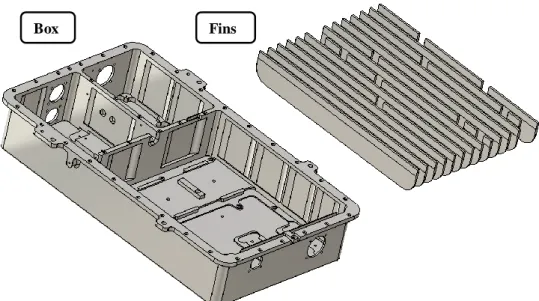
FIGURE 3.8:ORIGINAL BOX AND FINS ... 33
FIGURE 3.9:ORIGINAL UNDRILLED BOX AND UNCUT FINS ... 34
FIGURE 3.10:DIMENSION OF ORIGINAL FINS ... 34
FIGURE 3.11:DIMENSION OF NEW FINS ... 35
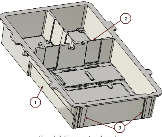
FIGURE 3.12:CHANGES MADE ON THE NEW BOX ... 36
FIGURE 3.13:POSITION OF INCREASED DISTANCE BETWEEN SCREWS ... 37
FIGURE 3.14:TWO OPTIONS CONSIDERED FOR DRAFTING ... 39
FIGURE 3.15:ASSEMBLY BY ONE SIDED FASTENING ... 40
FIGURE 3.16:ASSEMBLY BY TWO SIDED FASTENING (FIRST TYPE) ... 40
FIGURE 3.17:ASSEMBLY BY TWO SIDED FASTENING (SECOND TYPE) ... 41
FIGURE 3.18:POURING METHOD IN PLASTER MOLD CASTING ... 42
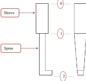
FIGURE 3.19TWO VIEWS OF A SAMPLE SLEEVE AND SPRUE ... 43
FIGURE 3.20:A TYPICAL CERAMIC FOAM FILTER ... 45
FIGURE 3.21:VARIOUS FILLET TYPES FOR SPRUE-RUNNER JUNCTION ... 45
FIGURE 3.22:SPRUE EXIT AREA (A2) AND ITS INCREASE AT BEND AND AFTER FILTER ... 45
FIGURE 3.23:GATING SYSTEM FOR RHEOCASTING ... 47
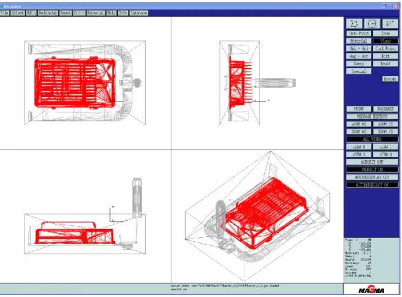
FIGURE 3.24:AN EXAMPLE OF A PLASTER CASTING SET UP AS SEEN IN THE PREPROCESSOR... 48
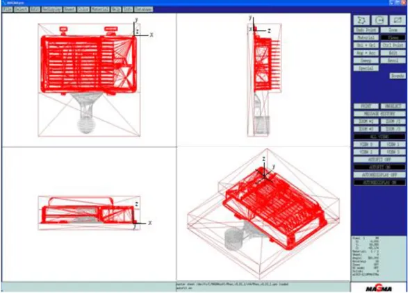
FIGURE 3.25:AN EXAMPLE OF A RHEOCASTING SET UP AS SEEN IN THE PREPROCESSOR... 49
FIGURE 3.26:DATUM PLANES FOR MACHINING ... 54
FIGURE 4.1:COMPLICATIONS DUE TO MESHING CURVES AND TAPERS ... 56
FIGURE 4.2:V6-V1,4MM GATE AT THE RECOMMENDED GATE VELOCITY OF 5 M/S... 58
FIGURE 4.3:V9-V2,6MM GATE SHOT AT A HIGHER GATE VELOCITY OF 5M/S (RECOMMENDED 4M/S) ... 59
FIGURE 4.4:V9-V3,6MM GATE SHOT AT A HIGHER GATE VELOCITY OF 8M/S (RECOMMENDED 4M/S) ... 61
FIGURE 4.5:V9-V1,6MM GATE SHOT AT A HIGHER GATE VELOCITY OF 15M/S (RECOMMENDED 4M/S)... 62
FIGURE 4.6:SLURRY STAYING BEHIND AT TURN OF CORNERS AT 55% FILL (V9-V1) ... 63
FIGURE 4.7:V9-V1,86% FILLED (LEFT) AND 94% FILLED (RIGHT) ... 63
List of figures and tables
FIGURE 4.9:V9-V5,NO AIR POCKET FORMATION FOR THE HIGH DENSITY MESH AT 86% AND 94% FILL ... 64
FIGURE 4.10:POCKETS NEAR FIN TIPS (V9-V5 HIGH MESH DENSITY) ... 64
FIGURE 4.11:V11-V1, LAYOUT TWO ... 65
FIGURE 4.12:V11-V2,LAYOUT THREE ... 66
FIGURE 4.13:FILLING OF INSIDE WALLS IN LAYOUTS TWO AND THREE ... 67
FIGURE 4.14:PROBABLE CAVITIES AT TOP OF FINS FOR RHEOCASTING ... 67
FIGURE 4.15:V9-V1, SOLIDIFICATION ... 68
FIGURE 4.16:V11-V1(LEFT) AND V11-V2(RIGHT) ... 68
FIGURE 4.17:HOTSPOT V9-V1 ... 69
FIGURE 4.18:HOTSPOT,V11-V1(LEFT) AND V11-V2(RIGHT) ... 69
FIGURE 4.19:THE TWO TYPES OF GATE USED THIN (V6-V1) AND THICK (V9-V1,V11-V1&V11-V2) ... 70
FIGURE 4.20:FSTIME_69,V6-V1(LEFT) AND V9-V1(RIGHT) ... 70
FIGURE 4.21:FSTIME_69, THIN GATE V6-V1(LEFT) AND THICK GATE V9-V1(RIGHT) ... 70
FIGURE 4.22:FSTIME_69,FEEDING PATH FOR V6-V1(LEFT) AND V9-V1(RIGHT) ... 71
FIGURE 4.23FSTIME_69,V6-V1(LEFT) AND V9-V1(RIGHT) ... 71
FIGURE 4.24:FSTIME_69,SLURRY BLOCKED FROM BEING FED V9-V1 ... 72
FIGURE 4.25:FSTIME_69,V11-V1(LEFT) AND V11-V2(RIGHT) ... 72
FIGURE 4.26:SINGLE GATED VERSION (PLASTER_ITERATION7_V2) ... 74
FIGURE 4.27:MULTIPLE GATED VERSION (PF4) ... 75
FIGURE 4.28:APPARENT SPRAYING AS MELT BENDS AT TOP ... 75
FIGURE 4.29: DIFFERENT TYPES OF FILTER CONFIGURATIONS ... 76
FIGURE 4.30:RESULT OF FILTER ARRANGEMENT 1(PF3) ... 76
FIGURE 4.31:RESULT OF FILTER ARRANGEMENT 2(PF4) ... 77
FIGURE 4.32:RESULT OF FILTER ARRANGEMENT 3(P_X_1) ... 77
FIGURE 4.33:TWO TYPES OF RUNNER EXTENSIONS CONSIDERED... 78
FIGURE 4.34:MELT ENTRANCE WITH SECOND TYPE OF RUNNER EXTENSION (P_X_1_V2) ... 78
FIGURE 4.35:TEMPERATURE DISTRIBUTION AT 837.68 SECONDS ... 79
FIGURE 4.36:HOTSPOT RESULTS, SHOWS JUNCTION OF INSIDE WALLS AS AREAS LAST TO SOLIDIFY ... 80
FIGURE 4.37:POROSITY RESULT ... 80
FIGURE 4.38:SOLIDIFICATION STAGES AT 8.02(LEFT) AND 897.04(RIGHT) SECONDS... 81
FIGURE 4.39:SOLIDIFICATION STAGES OF NEW VERSION AT 8.02(LEFT) AND 887.08(RIGHT) SECONDS ... 81
FIGURE 4.40:FEEDING THROUGH GATES SEEN ON THE FSTIME30 RESULT ... 82
FIGURE 4.41:POROSITY RESULT OF NEW VERSION... 82
FIGURE 4.42:MELT FALLING IN SLEEVE ... 83
FIGURE 4.43:POURING BY USE OF A POURING CUP ... 84
List of tables
TABLE 2.1:FOUR-DIGIT SYSTEM FOR DESIGNATING CAST ALUMINUM ALLOYS [3] ... 5TABLE 3.1:CASTING PROCESSES AND THEIR ATTRIBUTES [5] ... 26
TABLE 3.2:RECOMMENDED FAST SHOT VELOCITIES VS. GATE THICKNESS (RHEOCASTING) ... 50
TABLE 3.3:TYPICAL HEAT TREATMENTS FOR ALUMINUM ALLOY AND PERMANENT MOLD CASTING [14] ... 51
TABLE 3.4:PERMISSIBLE DEVIATIONS FOR LINEAR DIMENSIONS, NON-CASTING PROCESSES [20] ... 52
TABLE 3.5:PERMISSIBLE LINEAR DEVIATIONS FOR LINEAR DIMENSIONS FOR CASTING PROCESSES [21] ... 53
Introduction
1 Introduction
This chapter gives brief information on the thesis’s topic, aim and its structure.
1.1 Company description
Saab Avitronics is a business unit, within the Saab Group, which develops and manufactures advanced electronics primarily for military applications. It is one of the world's leading high technology companies with extensive involvement in defense, aviation and space. The head office is located in Järfälla, but the company also has offices in Kista, Linköping and Jönköping, all in Sweden. It also has divisions in Centurion and Cape Town, South Africa. The office in Jönköping develops and manufactures high-quality electronics, software and mechanical parts for aircrafts, helicopters and other demanding applications. Most projects are done for large international companies like Airbus and Boeing.
1.2 Background
From the very dawn of the aircraft industry, casted components have played an essential role as aircraft parts. However, the use of casted components still remains limited to parts with „non-crucial‟ role – parts having lax requirements. Nevertheless, in recent decades, the industry has seen the potential of cutting cost from a single component, when switching its mode of production to casting, instead of the conventional forged, machined, welded and assembled parts. Speed of production is also another cost related attribute that merits casting as a production process.
Other than the cost related benefits mentioned above, improvements in product predictability as well as growing technologies in casting methods, process control, testing methods and computer simulations, have also contributed to this growing trend towards using casting for producing aircraft components.
Despite the growth in technology and knowledge related to the process, memories of poor casting performance, as far as a few decades back, still haunts the industry and has slowed the utilization of casting benefits. Moreover at that time, the use of a “casting factor”, as a safety factor for casted components, increased the mass of a casted part, and thus has been another impediment in choosing casting as a process. Thus, it will take decades, if ever, to see crucial structures, having strict requirements, be produced by casting [1]. This thesis tries to study the possibilities of one conceptual aircraft component to be cast.
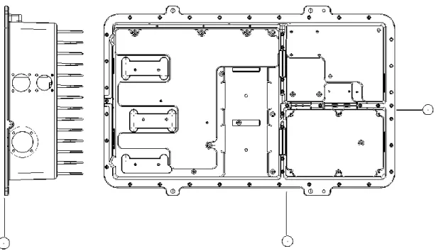
1.3 The product
The product was a chassis for an electric unit that was proposed to be used on a passenger plane. It was a concept for a business plan and did not exist on any passenger plane until the time of finishing this thesis. This chassis was planned to be placed inside a wing of a plane, in a somewhat harsh and open environment. The main function of the chassis would be holding and protecting an electronic unit from a harsh outside environment as well as carrying away heat. It also would have an additional function of conducting electricity at some surfaces. The power outage near this chassis would be about 3 to 5𝑘𝑊.
It had an overall dimension of 430 x 275 x 120 mm with a minimum section thickness of 1 mm. The original chassis was designed to be machined from a blank, which obviously was an expensive choice, leading to the motivation of looking into casting as another possible method of production. As the original chassis was to be made from wrought aluminum alloy, the choice of alloy for the cast chassis was set to be aluminum cast alloy. It should also be
Introduction
mentioned that the geometry of the original chassis was difficult to cast, in that it had varying cross-sectional thicknesses as well as having very thin sections. The chassis also had many holes, of which most were threaded and also had undercuts not attainable with most conventional casting processes – thus adding to the difficulty of casting it.
1.4 Purpose and aims
The main objective of this master thesis was to go through the product development aspects of a product, a chassis for an electronic unit, as related to switching its manufacturing method from machining to casting. This concept of proposing a cast chassis, encompassed going through, geometry modification, material (alloy) selection, process selection, simulation of selected process(es), prediction of defects, improvement of process parameters as well as an estimation of cost.
As an extension to the objectives above, the thesis also tried to show difficulties faced while simulating a casting process with certain material models, geometry features and process attributes, and thus, would hopefully serve as a guideline for future simulations of casting processes of similar shaped parts under similar conditions.
In trying to achieve the objectives mentioned above, the thesis also tried to involve casting companies, with the hope of having their knowhow as an input, and getting their confirmation to some assumptions as well as improvements made on this thesis.
The aim of this thesis work was to:
Modifying the products geometry to have better castability
Choose a casting process
Choose an alloy material
Have a sample gating system
Show areas susceptible to defects
Proposal of secondary processes and testing
A rough cost estimation
1.5 Delimits
The scope of this thesis was limited to the simulation of casting processes, with more emphasis given to filling results – in an attempt to evaluate and minimize potential defects. This was achieved by changing proposed gating systems as well as varying process parameters. The use of insulation, chills and cooling channels, to improve solidification pattern, was not considered. This thesis did not include a physical trial production of the chassis and thus comparison of simulation results with actual production outcome was also out of the scope of this thesis.
1.6 Outline
This thesis consists of six main chapters.
Chapter 1 gives a general introduction to the thesis.
Chapter 2 discusses the general concepts involved with process and material selection as well as brief descriptions of aluminum alloys, casting processes and simulation of casting processes.
Introduction
Chapter 3 lays down the main tasks performed and decisions made prior to simulation, which includes modification of the geometry as well as choice of material (alloy) and process. Chapter 4 presents some simulation results and discusses various changes and improvements made on the simulation of the processes.
Chapter 5 gives a rough cost estimation of the chosen processes and the last chapter. Chapter 6 gives the conclusion part of the whole thesis.
In addition, reference materials used for this thesis and an appendix, consisting of various tables and figures, are provided in chapters 7 and 8 respectively.
General Concepts
2 General concepts
This chapter gives introduction to the typical cast aluminum alloys as well as casting processes considered in this thesis. It also describes the production steps involved with casting as well as their associated problems. The common types of defects in casting aluminum are also introduced as related to what should be observed during simulation of casting processes (especially filling).
2.1 Product development
Product development is defined as: „Creation of products with new or different characteristics that offer new or additional benefits to the customer. It may involve modification of an existing product or its presentation, or formulation of an entirely new product that satisfies a newly defined customer want or market niche‟ [2].
Material selection and process selection are two important decision steps for a product concept. A product concept is first initiated by a new idea or a market need. This concept for a new product, with new characteristics or modified ones, will have to perform a certain task (function), which is associated to its geometry (shape), to the material used as well as to the method of producing it. This interrelationship between material, process, shape, and function is the central problem in realizing a product concept. A change or choice of one affects the other. This dependency, of the four areas of concern in product development, can be represented with a diagram as shown in figure (2.1).
Figure 2.1: Interrelationship between process, material, shape and function [12]
2.2 Material Selection
A material has properties, both physical and mechanical, that makes it a candidate to perform a certain function and/or to be shaped by a certain process. These properties are density, strength, corrosion resistance, thermal conductivity, specific heat capacity, etc. In addition to the properties mentioned above, the cost of the material is also another factor affecting its choice. Thus, based on the requirements from its function, constraints from the process(es) as well as its shape, an affordable material, having the best possible properties has to be chosen. In this thesis, a choice would be made from a list of applicable aluminum cast alloys.
General Concepts
2.2.1 General
Aluminum alloys, together with titanium, magnesium and beryllium constitute the group Light Alloys¨. The obvious primary advantage of aluminum (light alloys) in engineering (structural) applications is the high strength per density value it has, compared to other materials in general or iron or steel in particular. Moreover aluminum is very abundant in the earth‟s crust. This has made aluminum a major choice as a material for different components in the transportation industry, with aerospace and vehicles being the primary application areas. The low density of aluminum also has an extra advantage in stiffness that gives it resistance to buckling. However, other than the advantages associated with low density, aluminum alloys have very attractive properties like high corrosion resistance as well as high thermal and electrical conductivity. Aluminum alloys are part heat treat able and part not.
2.2.2 Cast Alloys
Aluminum cast alloys have the advantage of having a relatively low melting temperature when compared with traditional cast iron. Thus, low energy input is required. Moreover, cast aluminum alloys are less soluble to all gases, except hydrogen. Good surface finish and fluidity, (for most) are also other properties that make cast aluminum alloys a candidate for choice. A major disadvantage of using aluminum as a casting material is its problem with shrinkage. Aluminum alloys have a relatively high shrinkage while solidifying and this should be put into account while designing, so as to produce a product that is dimensionally accurate, less susceptible to defects and a minimized residual stress.
Generally, aluminum cast alloys have inferior mechanical properties compared to wrought aluminum alloys except in creep. However, if a sound casting can be produced, cast alloys will come in handy in reducing cost of a product.
The relatively low melting temperature and general ease of handling of cast aluminum, has been an aid for developing processes like rheocasting and squeeze casting – two methods of casting that have the advantage of producing products with relatively better mechanical properties.
2.2.3 Designation
Cast aluminum alloys have designations to identify as well as group them based on alloy constituents. One such designation is the one developed by Aluminum Association of the United States, which uses a four digit system and as shown in table (2.1).
Current designation
Former designation
Aluminum, 99.00% or greater 1xx.x
Aluminum alloys grouped by major alloying elements:
Copper 2xx.x 1xx
Silicon with added copper and/or magnesium 3xx.x 3xx
Silicon 4xx.x 1 to 99 Magnesium 5xx.x 2xx Zinc 7xx.x 6xx Tin 8xx.x 7xx Other element 9xx.x 7xx Unused series 6xx.x
General Concepts
The first digit indicates the major alloying element which is the base for forming the alloy group shown in table (2.1).
For the 1xx.x group alloys, the second and third digits indicate the minimum percentage of aluminum for the 1xx.x group alloys- they are equal to the percentage of impurity (150.x indicates a composition containing a minimum of 99.50% aluminum). For the alloy groups 2xx.x to 9xx.x, they have no individual significance but to serve as a number to identify the different aluminum alloys.
In all casting alloys, the last digit after the dot indicates the product form: where 0 is for castings, 1 for standard ingot and 2 for ingots having narrower composition limits, but still being within the ranges of the standard ingot.
A serial letter is usually included before the numerical designation to indicate a specific modification carried out on the original alloy, or specifying variation in impurity limits from an original alloy. These letters are assigned starting with A in alphabetical order, leaving out I, O, Q and X (X used for experimental alloys).
As with the case with aluminum alloys in general, which were mentioned earlier to be part heat treatable and part not, cast aluminum alloys are also part heat treatable and part not. Specific designation, which works for both wrought and cast alloys, exists for describing the temper an alloy should have. This temper designation follows after a hyphen put at the end of the alloy designation described above, and usually has two characters. The first character is a letter for the basic temper designation and the latter a digit that indicates the temper subdivision (in some cases two digits are also found).
Typical heat treatment types are:
F, as cast
O, annealed
T4, solution treated and aged
T5, precipitation hardened
T6, solution heat treated, quenched, and precipitation hardened
T7, solution heat treated, quenched and overaged
Another common designation variant, commonly used is addition of the letter “P” added to a standard temper (e.g. T6P), indicating a producers variation of the standard heat treatment process [3].
2.2.4 Standard materials in the aviation industry
In relation to this thesis, as per the requirements of the aviation industry, there exists a list of materials that can be used for different aircraft applications.
Cast aluminum alloys, along with the temper requirement, that can be used for structural applications are: A201.0-T7 354.0-T6 355.0-T6 C355.0-T6 356.0-T6 A356.0-T6(T6P) A357.0-T6
General Concepts
D357.0-T6
359.0-T6
General properties and applications of the alloys mentioned above are described below [4]. A more detailed information on the properties of these alloys is provided in appendix (8.1).
A201.0 – an Al-Cu-Ag alloy, heat treatable. In its T7 temper it has high strength (among the
highest for commercial cast materials) strength and hardness, moderate ductility and very high resistance to stress corrosion cracking, can be sand cast, permanent mold cast and investment cast, limited weldability.
Applications include aerospace housings, missile fins, and other applications where strength at elevated temperatures, high strength with moderate elongation is required.
354.0 – an Al-Si-Mg alloy, heat treatable. Has high strength and hardness, very good fatigue
strength, processing, moderate general corrosion resistance generally processed by permanent mold casting and have moderate weldability.
Typically used for castings requiring very high strength.
355.0 – an Al-Si-Mg alloy, heat treatable. Has good strength and hardness but very low
elongation, good castability and pressure tightness, moderate general corrosion resistance, generally permanent mold casted and have moderate weldability.
Applications where good castability and pressure tightness is required.
C355.0 – an Al-Si-Mg alloy, heat treatable. Similar to 355.0 but with impurities controlled to
be low, resulting in relatively higher strength and hardness with improved elongation, have moderate weldability
Applications include aircraft supercharger covers, fuel-pump bodies, liquid-cooled aircraft engine crankcases, general applications where good castability and pressure tightness is required.
356.0 – an Al-Si-Mg alloy, heat treatable. Has intermediate strength but high hardness and
low elongation, good corrosion resistance, very easy to handle (among the easiest) in variety of casting processes and have good weldability.
A356.0 – an Al-Si-Mg alloy, heat treatable. Similar to 356.0 but with impurities controlled to
be low, resulting in relatively higher strength and hardness with improved elongation, high corrosion resistance, and good weldability.
Applications include aircraft pump parts, aircraft fittings and control parts, aircraft structures and other applications where excellent castability, good weldability, pressure tightness, and good resistance to corrosion are required.
A357.0 – an Al-Si-Mg alloy, heat treatable. Special properties developed by controlled
casting and chilling. Has high strength and hardness, moderate elongation, generally good weldability, very good corrosion resistance and good toughness, typically permanent mold casted.
Applications include aircraft and missile parts requiring good weldability, strength, and toughness, critical aerospace applications.
D357.0 – an Al-Si-Mg alloy, heat treatable. It is a modification of A357.0 alloy, requiring
narrower composition limits and a more controlled processing. Has very a relatively higher strength and hardness, moderate elongation, with very good fatigue strength, good weldability.
Applications include critical aerospace applications and other uses requiring high strength and good toughness.
General Concepts
359.0 – an Al-Si-Mg alloy, heat treatable. Has very high strength and hardness, moderate
elongation, high, with very good fatigue strength, generally good weldability, very good castability, typically permanent mold casted.
All the alloys mentioned above are not restricted to the casting processes they are associated with; instead all can either be sand casted, permanent mold casted and investment casted. Almost all casting processes can be used to processes the alloys depending on the property requirement of a product or other constraints like cost or section thickness, etc.
2.3 Process Selection
Product manufacturing has usually three stages, which are, shaping, joining and finishing. A selection of process is affected by or affects the choice of material, the shape (usually minimum section thickness), the mass of the product as well as the dimensional precision and surface finish requirements. Usually, a final surface finish and dimensional tolerance is attained by a secondary machining or coating process. At the end of the day, the choice of process(es) made, should be cost conscious. It was mentioned that, the shaping process to be used on the product, was set to be a casting process.
Casting (metals) is one of the oldest methods of shaping a product. It is a primary shaping process and involves melting of metals (usually superheating to a proper temperature), followed by pouring of the liquid metal into a pre-prepared cavity or mold, where it is allowed to solidify and thus take the form of the cavity. Generally, any metal that can be melted can be cast. Compared to other shaping processes, it has the advantage of forming complex geometries having features like internal cavities, holes as well as complex surfaces. It also has the advantage of being able to shape metals that are otherwise difficult to machine. Its major disadvantages are the common defects it entails – shrinkage and porosity being some examples.
Casting processes are most commonly categorized into two constituents, depending on the use-frequency of mold. These are, permanent mold casting (non-expendable mold casting) and expendable mold casting.
Expendable Mold Casting includes processes like, sand casting, shell casting, investment casting (lost-wax casting), lost foam casting, plaster mold casting, ceramic mold casting, etc. Permanent Mold Casting includes (high pressure-, low pressure-, gravity-) die casting, centrifugal casting and special processes like rheocasting and squeeze casting.
2.3.1 Expendable mold processes
A. Casting processes with sand based molding
- Green-sand molding: A casting process that has green (term stands for non-cured
sand, its color is actually black) sand as a mold material. It is the most widely used casting process. The sand is blended with clay water and additives. It is the leading, out of the least expensive casting processes, and is a process with low tooling cost. Depending on whether one dries the entire mold or the part contacting the casting, dry-sand mold and skin-dried mold (respectively), are variants of green- sand mold casting that mitigate its problems tied with moisture.
- Sodium silicate-CO2 molding: This has sand with addition of 3% to 6% sodium
General Concepts
to CO2. However, it collapses relatively easily and additives might be added to improve this. It is usually used when better accuracy, thinner sections, or deeper draws are required than usually achieved by ordinary sand molding.
- No-bake molding: An alternate process that uses reaction between an organic and
inorganic resin binder with liquid curing agents serving as a catalyst. These are combined with sand. It has a relatively slower mold curing time.
- Shell molding: A mixture of silica sand that has fine grains is mixed with a
thermosetting resin that is dropped, blown or shot onto a heated metal pattern (usually some cast iron). This heat partially cures a layer (about 10 mm thick) of sand-plastic material that forms the shell. A complete mold is made of two shell halves. The shell is usually supported by sand in a box from the outside, in order to withstand the stresses that arise during the process.
Figure 2.2: Sand casting [5]
B. Plaster mold casting: In this process the mold is made of plaster of paris (gypsum), combined with additives to give it strength, permeability and formability. The process gives excellent surface finish and dimensional accuracy (especially with metal patterns). The plaster has low thermal conductivity and low specific heat and thus cooling of casting is very slow. This helps molten metal to stay alive (stay hot) and make it flow to fill thin sections and replicate fine details. Sometimes plaster molds are preheated prior to pouring of molten metal. Unfortunately, it is usually limited to low melting point metals (aluminum, magnesium and zinc).
Figure 2.3: Plaster mold casting [5]
C. Ceramic mold casting: It is similar to plaster casting except that the mold is made of ceramic material. Like plaster casting this process is able to give fine details, smooth surface and achieve thin sections. Ceramic molds are often preheated to ensure proper filling of molten metal. Contrary to plaster casting it is able to cast metals with high melting point. Unfortunately, the mold material is expensive (and of course, it is not reusable).
General Concepts
Figure 2.4: Ceramic mold casting [5]
D. Investment casting: It is also known as the Lost-Wax casting process. Mold material for investment casting is ceramic material that is similar to ceramic mold casting. This process is different in that the pattern used is disposable i.e. a wax material around which the mold is set. The pattern is not removed prior to pouring of molten metal (cavity less casting), instead the wax melts and is vented out, as it is being displaced by the molten metal poured over it. The mold is then destroyed to deliver the casting. Two variant of molding processes exit. These are, the solid mold type (has cope and/or drag) and the ceramic shell molding type (stand alone ceramic that is built up on pattern, no container) of processes. The latter is the frequented method of the two. In ceramic shell molding, multiple parts, making a single pattern are arranged in a tree-like structure and share the same gating system.
Figure 2.5: Investment casting [5]
E. Lost-foam casting: Another cavity-less casting process, similar to investment casting but having sand as a mold material. Pattern in this case is made of polystyrene foam. It needs the use of a flask to hold sand together and a single cavity or multiple cavities (tree-structure) can be formed. The mold is destroyed to get the final casting.
General Concepts
It should be noted that, in both Investment and lost foam casting, there is no need to remove pattern and mold material is expendable. Thus, almost no draft is required on patterns and features like undercuts are no trouble to shape.
2.3.2 Non-expendable mold processes
A. Die casting
- Gravity-die casting: It is also known as permanent mold casting. A die is made out
of a suitable material usually nodular cast iron, cast steel or wrought steel (for low temperature melting metals). The mold is usually is preheated and coated prior to filling with molten metal which fills the cavity by gravity force. Near net shape cast can be achieved. It has the advantage of controlling cooling through good design by introducing cooling channels. Since the molds are not permeable, vents must usually be provided. A graphite mold makes casting of iron and steel possible, but can be very expensive. Generally, with this process, a very high quality casting (surface, dimension) requiring very little machining is achieved.
Figure 2.7: Gravity-die casting [5]
- Low pressure die casting: Here, the permanent molds are mounted over a sealed
furnace with a refractory tube placed between the two. By pressurizing the furnace, molten metal is driven up and fills the cavity. Thus, the metal is exceptionally clean, as it is extracted from melt center and fed directly to the cavity, with the tube protecting it from reactions. The casting solidifies from top down, as pressure is kept from bottom, till it solidifies. It has a relatively slower cooling than gravity mold casting. It is suitable for metals with low melting points.
Figure 2.8: Low pressure die casting [5]
- High pressure die casting: Here, molten metal is injected, under high pressure, into
a metal die. The metal flows through channels and pressure from a plunger is kept until the casting solidifies. Due to very high pressure, die halves require a clamping mechanism. It is often used to cast metals with low melting points, typically zinc, due to theirs low reaction with the mold, during the long and pressured contact. Very high
General Concepts
surface quality castings as well as excellent dimensional accuracy can be achieved. Two varieties of this process are common, namely cold chamber and hot chamber pressure die castings. The former has melt poured in front of a plunger, while the latter has the plunger already sunk in a melt container. High pressure die casting has a very expensive tooling and equipment cost.
Figure 2.9: High pressure die casting [5]
B. Centrifugal casting: In this process, molten metal is distributed into mold cavity by the internal (centrifugal) forces of a rotating die. Rotation could be on a vertical or horizontal axis. Mold materials include baked sand, plaster or graphite.
Figure 2.10: Centrifugal casting [5]
C. Squeeze casting: Here, molten metal is introduced into die, with low velocity and after the cavity is filled a high pressure is applied on the die. It is commonly used for metals with low melting points. The process offers a very close-to-net-shape casting.
Figure 2.11: Squeeze Casting [5]
D. Rheocasting: In this process, molten metal is cooled to a semisolid state with a constant stirring and the melt will be made to have a slurry form. The stirring action cuts off dendrites or actually prevents dendrites from forming and results in rounded solid particles in the slurry. This slurry, containing up to 30-50% solid, is then shot into a die, by use of a plunger. It is commonly used for metals with low melting
General Concepts
points, typically aluminum. The process offers a very close-to-net-shape casting that is almost porosity free.
Figure 2.12: Rheocasting [6]
2.3.3 Basic casting terminologies
A two-part mold of a simple geometry is shown in figure (2.13), followed by some basic terminologies used in the casting world.
Figure 2.13: Two-part mold of a simple geometry [7]
- Pattern: an approximate replica of the desired casting. Geometry includes an
allowance for shrinkage plus has extra features like cores (if any) as a union.
- Mold material: a material which is aggregated around the pattern, where upon its
setting and subsequent removal of the pattern material, a provision (the mold cavity) is left. This cavity is where melt would later be poured in and left to solidify.
- Flask: a rigid material, usually from metal or wood that holds the mold material
intact.
- Cope: top half of the flask, mold, pattern or core.
- Drag: bottom half of the flask, mold, pattern or core.
Cope and drag are only used for horizontally parted mold.
- Core: a material, usually sand (or metal) left in mold cavity around which molten
metal solidifies for purpose of making holes and other hollow feature. The core together with the mold material makes the mold cavity.
General Concepts
- Core print: a recess left in mold for purpose of holding core firmly while casting.
- Riser: an extra recess made in mold for purpose of feeding shrinkage in the mold
cavity.
- Gating system: a network of channels in the mold that deliver molten metal from a
pouring vessel (that transports molten metal from furnace) to the mold cavity. It usually comprises of, a Pouring Cup (a cavity that receives melt from the pouring vessel), a Sprue (a vertical portion of the gating system), Runners (horizontal portion of the gating system) and Gates (channels that controls entrance to mold cavity). Other features like Wells (sprue well and extension wells) and Extensions (runner and flash) are also common features that make up a gating system.
- Parting line (parting surface): an interface that separates two mold halves.
- Draft: a taper made on pattern that results in a taper on the mold cavity and then a
taper on the solidified piece (casting) to ease removal of the pattern and the final casting.
The terminologies above can loosely be used to all type of castings but are more endemic to non permanent, especially gravity filled, casting processes. Analogous terms used for permanent die casting, especially to high pressure die casting, are defined below together with the corresponding figure (2.14).
Figure 2.14: Cold chamber die casting machine [7]
- Die: a rigid block that has the desired casting shape as a cavity. It is usually made of
two halves (the ejector die and the cover die).
- Ejector die: the part of the die half that is stationary.
- Cover die: the part of the die half that moves to take out casting.
- Plunger: a piston that forces the melt into the cavity.
- Shot sleeve: a pre-cavity container where the plunger works.
- Biscuit: an excess of ladled metal remaining in the shot sleeve of a cold chamber die
General Concepts
- Overflow: a recess in a die connected to die cavity by a gate to assist in proper
venting.
2.4 Fundamentals & associated problems
Casting process involves carrying out a series of activities. Some literatures divide these activates into six processing steps [8]. These six steps along with the tasks carried out during these steps and the associated problems would be described next.
Step One: Mold cavity making
This step consist of all processes associated with making the casting cavity. Thus, the process of pattern making and core making are also included in this step. In expendable molds, mold material is usually aggregated around the pattern, while in permanent molds, the shape of the pattern is machined out of an appropriate mold material. In both cases, the pattern must have an appropriate size to account for shrinkage and must have an adequate draft to facilitate its removal or the removal of the final casting. Common problems associated with this step are core blows, mold permeability, mold erosion, mold expansion and excessive residual stress. The first three problems are typically associated with expendable molds, while the last one is typical of permanent molds. Thus, care should be taken in selecting an appropriate mold and core material as well as designing the mold assembly, the pattern size and the draft on the pattern.
Step Two: Melting process
In this step the alloy material is heated and turned into liquid. The melt is usually heated above its melting temperature. Problems associated with this step are premature solidification and cleanliness of melt. To avoid these problems, the melt should be superheated to an adequate temperature. Moreover, proper care should be taken to avoid foreign inclusions from entering the melt as well as preventing unwanted reactions of the melt with its environment. Other typical problems associated with cast aluminum alloys are high hydrogen solubility and oxide formation. As much as possible, lowering the super heat of metal to be cast, is desired since it lessens these reactions that form oxides and gas solubility. A low super heat also saves the energy required for melting an alloy.
Step Three: Pouring process
This step involves the transfer of molten metal from one container to another as well as the filling of the mold cavity. Thus this pouring happens at various stages of the casting process. First, the melt can be transferred from the melting furnace to a holding furnace. Next, the molten metal can be transferred from the holding furnace to the casting cavity or a shot chamber depending on the type of casting process. Finally, the subsequent filling of the casting cavity by the molten metal is also part of a casting process considered here. This step is the area where most casting defects are generated (see section 2.5 for details). Fluidity is a term given to the ability with which molten metal can flow. In most cases fluidity of molten metal is improved by adding specific alloys, in a process called alloy modification. Generally, care should be taken in designing gating systems as well choosing associated parameters like velocity and filling time of casting processes.
Step Four: Solidification Process
This steps involves the solidification of molten metal. During solidification, shrinkage of casting should be fed by a proper method so that internal voids and porosities would be avoided. Hotspots, are areas that solidify last in a casting and usually takes as an indication for areas susceptible for porosity formation. Another problem
General Concepts
associated with solidification is the warping of components, which usually happens to dished-type components. The cooling rate during solidification is an important process parameter deciding the final property of the casting. Generally faster cooling rate gives better mechanical properties. However, formation of a desired microstructure can be assisted by using grain refinement and controlling the solidification direction.
Step Five: Removal of casting from mold
In this step the casting, which has solidified, is removed from the mold. Care should be taken so as not to chip the cast or mold (if it is to be reusable). Also non adequate drafts might make removal of the cast part from the mold difficult. Non-Reusable molds can be crushed away from the cast part. However, the applied crushing force must be just enough to take away the mold and not disturb the cast part.
Step Six: Various cleaning, finishing and inspection processes
Subsequent processes like quenching and heat treatment should be studied if they attain a desired micro structure. Appropriate surface treatment process should be chosen to prolong the components life. Other secondary processes like machining and joining need a proper consideration so as not to have too little or too much surface to machine. Moreover, cast parts need a clear-cut designation of datum lines as a reference for providing dimensions.
2.5 Defects in aluminum casting
Defects in casting originate from three areas [17]. These are the casting design, the technique of casting and the application of the technique (workmanship). A defect may be traced back to a single cause or be from a combination of factors which might not be easy to pin down. The different steps in casting, and the care required in these steps to avoid defects in castings, have been briefly touched above. It was also mentioned that, out of the six casting steps, the pouring step accounts for the majority of defects that occur in castings (aluminum casting in particular). Thus, here concentration would be given to entrainment defects, to highlight what must be studied, in a flow simulation and to give emphasis on such defects as they account to a vast majority of the defects and failures occurring during casting a product and while the cast product is in-service.
Entrainment defects can be divided as [9]:
Exogenous inclusions
Bubbles
Bifilms
Before explaining about the defect types, it is worth mentioning two characteristics of aluminum.
The first is that aluminum has hydrogen, as the only gas appreciably soluble in it. The solubility of hydrogen increases with temperature, especially rapidly above the liquidus temperature. This dissolved hydrogen might eventually result in hydrogen porosity. Depending on the distribution of these pores, this type of „defect‟ might even be desirable (if finely distributed). Unfortunately, the technology with which to produce a product with the above desired distribution of pores is not yet refined and hydrogen porosity is generally thought to be undesired.
General Concepts
The second characteristic of aluminum is that it readily oxidizes, either in solid or liquid form. Oxides can be formed by reaction with air, vapor or other oxides that come in contact with aluminum. This oxide forms on any surface that is exposed to air.
Coming back to the first type of defect, exogenous inclusions are grains of foreign matter that find their way into the melt and subsequently ending up in the final casting. The source for these inclusions might be some materials being dislodged from a furnace‟s, a holding container‟s or a ladle‟s wall.
The second type, bubbles, are hollow globules of gas entrained in the melt. Eventually these bubbles might end up as a porosity defect in the casting. Even if these bubbles escape to the surface due to buoyancy, they result in a more critical defect termed as a bubble trail. As can be understood from the term, bubble trail is a trail left by a bubble as it travels through the melt. This trail looks something like the tail of a comet and can be seen in figure (2.15). These bubbles and bubble trail defects account for the majority of defects in castings and are much attributed to poor pouring processes, while core blow could also be another cause for their formation.
Figure 2.15: Bubbles and bubble trails [9]
Central to the above mentioned types of entrainment defects is the third type of entrainment defect- which is the concept of a bifilm. It was mentioned earlier that aluminum readily oxides and that this oxide form a coat around the melt. If this outer surface folds and meets, dry side to dry side, the resulting formation is termed as a bifilm. Naturally these biflms will form inwards and might again find their way into the casting due to poor pouring and flow conditions. A figure showing these bifilms and how they relate with the first two defects can be seen in figure (2.16).
General Concepts
Figure 2.16: Bifilms (Entrainment defects) [9]
In the figure (2.16,a), a new bifilm can be seen, where (2.16,b) shows how bubbles are formed integrally to a bifilm. In (2.16,c,d,e), it can be seen how bifilms can trap liquid, a debris entrained in a bifilm as well as sand particles trapped in a bifilm. The last part (2.16, f) shows an old film that has a debris as an inclusion, itself trapped in a new film. Thus, that was why the concept of bifilms were claimed to be central to entrainment defects.
As mentioned earlier, poor pouring and flow patterns result in the formation of bubbles and bifilms as well as for them to find way into the casting. These entrainments can occur in both turbulent and laminar type flows and also when the fall height of a melt is large.
As an example, the effect of increasing the height of drop on the formation of bubbles and bifilms can be seen in figure (2.17).
General Concepts
In the figure (2.17, a), the molten stream is seen to fall and join the melt with the outer boundary staying intact and thus not forming bifilms. A slight increase in height (2.17, b) shows the stream falling and joining the melt to form a dross ring that is still intact but forms bifilms that stay on the surface of the melt. Still another increase in falling in height (2.17, c) shows how bifilms being formed and being carried deep into the body of the melt. Thus from (2.17) it can be seen how increase in falling height increases the probability of bifilms to form.
Another example of bifilm formation due to a turbulent flow is when a melt is having a high velocity coupled with a non-proportional increase in channeling area. This might create splashes as well as disintegration of the melt front into small forerunning melt volumes that ultimately form bifilms upon the subsequent meeting with the tailing melt. This splashing of molten metal and how bifilm might be formed is shown in figure (2.18).
Figure 2.18: Sketch of a surface entrainment event [9]
As hinted earlier, having a laminar flow is not a sufficient condition for ensuring bifilms are not formed. What is wanted from a flow is to have the melt expanding, like a balloon being inflated, at all front and thus filling the cavity by having the oxide skin end up as the casting‟s surface. Failure to do so, even with a laminar flow (when melt not expanding at all fronts), might also result in bifilms. As an example, in figure (2.19) shows such a case, where bifilms form when melt laps due to an intermittent start-and-stop kind of filling.
General Concepts
Figure 2.19: Formation of laps [9]
Another common phenomenon that results in the formation of bifilms is the separation of melts, upon passing through different channels, and then meeting again to form what is termed as a confluence weld. Confluence weld also forms when melts separate when hindered by a core material placed in the cavity for creating holes. Confluence welds can be seen in figure (2.20).
Figure 2.20: Confluence welds [9]
Other modes of bifilm formations exist, but the above descriptions give enough insight into what bifilms are in particular and what entrainment defects are in general.
General Concepts
These bubble formations, and entrainments cannot be explicitly evaluated by any simulation. Nevertheless there exists a criterion for a critical velocity that must not be exceeded during filling that might serve as a limit beyond which formation of such defects is very probable. This critical velocity is approximately 0.5 m/s for all metals [10]. This value is almost always exceeded, especially for pressure die casting process. For casting processes other than pressure die casting this criteria is desirable. If this velocity can be achieved it is assumed that the filling would give lesser defects. If not, values of up to 1 m/s particularly for thin walled castings have also been said to give satisfactory castings, by researchers. Unfortunately, aluminum needs to drop only 12.5 millimeters in order to attain this critical velocity! Thus, if exceeding this criterion cannot be helped, the preferred practice is to try to contain the melt close-bound by the channeling and cavity walls, in order to avoid splashing and sprouting. Accordingly, during simulation, the flow velocities, whether too high or too slow, can be taken as one indication of whether the flow has a potential for resulting in entrainment defects. Other than the magnitude of flow velocity, splashing and sprouting occurrences in the flow can also be observed, and tried to be minimized. Flow circulations should also be watched out, as vortex actions might generate bubbles.
As mentioned earlier, flow velocities in pressure die casting (rheocasting included), always exceeds the critical velocity. Thus, what should be used as a criterion for flow evaluation is the latter method of watching out splashes and sprouts in melt.
As a conclusion what should be stressed here is that entrainment defects account for the majority of casting defects and they are related to the pouring (filling) step of the six casting steps described earlier. Thus observing the filling action of the melt is invaluable. It aids in improving the filling pattern by varying the process parameters or by changing the geometry or layout of the gating system. Ensuring that these defects are less probable to develop while pouring would also mean that associated defects like porosity and cracks that develop by unfurling of bifilms during solidification are also less probable to occur.
Other defects:
Other defects that could also be looked at during simulation are mis-runs and cold-shuts in flow simulations while shrinkage cavities/porosities, surface sinks, contraction defects and hot tears, etc. are observed in solidification and stress simulations.
General Concepts
2.6 Simulation
The need to shorten the time and reduce the cost of product development has accelerated the use of computer simulations. Simulation is a method for understanding processes and a tool for optimizing them. To this end, the technology of simulation of casting processes has grown extremely fast in recent decades and has been proved to provide results comparable to physical processes.
Simulation of casting processes usually involves three areas. These are calculating the melt pouring process-a fluid flow problem, calculating the solidification process-a heat transfer problem and calculating stresses-a solid mechanics problem. These three areas of calculation are the basis of any casting simulation software that is used to study process behaviors or optimize a process.
From simulation of a mould filling process, one can study the filling pattern of the melt to see, if air is trapped while pouring, if there will be areas in the cavity which might not fill completely, if there is a flow circulation, if there is a folding of melt, etc. Velocities at different areas of the melt might also be evaluated to see if a mold (non-permanent mold) is susceptible to erosion due to high melt velocity. As mentioned earlier a very high velocity might result in a turbulent flow as well as a non-intact melt front. Moreover, too low a velocity might lead to laminar flow problems as well as holding back of the melt front, which might result in cold-shuts – if temperature gets too low at these areas. Observation of the final temperature after pouring also shows if the casting can be fed sufficiently during solidification.
From simulation of a solidification process, one can observe the solidification pattern to study areas which are prone to solidification shrinkage as well as hotspots. Moreover, observing the temperature as well as time and duration of the solidification simulation helps to evaluate if a feeding is sufficient or conversely, to design a better feeder. Study of cooling curves at areas of interest in the casting helps to predict the resulting microstructure from the process. From calculation of stresses, one can study the residual stresses that develop in the casting. This aids in improving the geometry of the casting or varying the process parameters in order to decrease residual stresses in castings. This simulation area, though equally important, is not as frequently carried out as the first two. This is because casting industries still do not consider studying residual stresses is very important and also because results from such calculations are still doubted, with regards to approximating the actual physical stresses that develop.
The advantage of simulating a process, over production trial runs or physical experiments, was mentioned to be the saving of time and cost. Simulation also has the ability to get and visualize different outputs at the same time (velocity, temperature, pressure, stress). Nevertheless, since some simulations might take weeks to run and optimization an iterative process, a project might take months to finish. Thus, a wise decision has to be made on how long a time one is willing to sacrifice. Typically, not so many industries use simulation as a tool for optimizing their processes. Instead, each industry has its own invaluable knowledge reserve, from years of experience that it uses in designing a process. Unfortunately, because of business competition between industries, a company may not be keen on sharing it‟s know-how to an outsider. However, what one cannot shy away from is that the result of integrating experience with simulation has proven to be a very powerful as well as rewarding method of optimizing processes, thus triggering a growing trend, among casting companies, towards adopting it as a practice.
General Concepts
2.6.1 MAGMASOFT (V 4.4)
MAGMASOFT (V4.4) is the simulation software used in this thesis work. It is capable of simulating melt flow as well as solidification and stress.
It is a complete system that provides a:
Preprocessor: this is used to build or import geometries that are used to simulate a process. The geometries normally include: the casting (the desired final shape), the gating system (the channel that delivers melt into cavity) and the mold.
Enmeshment: this is used to mesh the geometries.
Simulation setup: here the various process parameters and specific materials as well as their properties as set.
Numerical calculation: based on chosen materials and their properties as well as process parameters set, the software calculates for outputs the user desires (like stress velocity, temperature, etc.).
Postprocessor: here it gives a 3D graphical presentation of the results.
MAGMAsoft has various modules that enable it to simulate almost all types of casting processes. Thus, in relation with this thesis, the normal shape casting(batch production) module was used to simulate the plaster casting process while the high pressure die casting module (MAGMAhpdc) with activation of the thixo-mode, was used for simulating the rheocasting process.
MAGMAthixo
Rheocasting was mentioned to be a thixoforming process and thus, as a precondition, the material used has to show two properties. These are pseudoplasticity and thixotropy. With psuedoplasticity, the material shows a decrease is viscosity with increase in shear rate, while with thixotropy, the stress in the material does not only depend on its current state of deformation (motion), but also its recent deformation history [11].
A rheological model governs the way such a non-Newtonian fluid flows or deforms. This is typically performed by making use of apparent viscosity models. MAGMAsoft has two such models. These two models are the Carreau-Yasuda model and the Ostwald-de-Waele model, of which, the latter was available and used for this project.
Other commercial software also exist, Starcast, QuikCAST, ProCAST, InteCAST, NovaCast are examples of such software.
Groundwork
3 Groundwork
This chapter discusses the various decisions made in choosing a cast alloy, casting processes as well as the geometry modification carried out on the chassis. It also describes the steps and considerations taken while designing the gating systems. The setup parameters used in simulations as well as some aspects associated with secondary processes are also discussed briefly.
3.1 Product requirement
As briefly mentioned in the first chapter, the original chassis was first designed with a plan to machine it from a blank. Thus, the product attributes of the original chassis were taken as a benchmark for setting the new chassis‟s requirement. This requirement was then used to select suitable casting processes and the corresponding cast alloys for the new chassis. The product attributes for the original chassis is given below:
Original Chassis:
Material – Wrought Aluminum 6082 - T6
Overall dimension ~430 x 275 x 120 mm
Mass~ 4 kg
Minimum section thickness~1 mm
Tolerance - as per SS-ISO 2768-1
Surface roughness – Ra 3.2 μm
Surface treatment – Colourless chromating ACC SS-ISO 10546 Class 3
Thread tolerance 6h-6H
3.2 Material screening
In chapter two, it was discussed that the aviation industry had a list of cast aluminum alloys that can be used as an engineering material. These aluminum alloys were mentioned to be:
A201.0-T7 354.0-T6 355.0-T6 C355.0-T6 356.0-T6 A356.0-T6(T6P) A357.0-T6 D357.0-T6 359.0-T6
The physical and mechanical properties of these nine alloys as well as their alloy compositions were evaluated against that of the wrought alloy. This served as the first step towards narrowing down on a specific alloy.
![Figure 2.14: Cold chamber die casting machine [7]](https://thumb-eu.123doks.com/thumbv2/5dokorg/5484207.142768/22.893.265.638.539.844/figure-cold-chamber-casting-machine.webp)
![Figure 3.1: Relative cost of casting an aluminum rod versus the number of parts to be cast [12]](https://thumb-eu.123doks.com/thumbv2/5dokorg/5484207.142768/35.893.182.710.214.620/figure-relative-cost-casting-aluminum-versus-number-parts.webp)
![Table 3.3: Typical heat treatments for aluminum alloy and permanent mold casting [14]](https://thumb-eu.123doks.com/thumbv2/5dokorg/5484207.142768/59.893.148.751.682.848/table-typical-heat-treatments-aluminum-alloy-permanent-casting.webp)
![Table 3.5: Permissible linear deviations for linear dimensions for casting processes [21]](https://thumb-eu.123doks.com/thumbv2/5dokorg/5484207.142768/61.893.115.780.150.538/table-permissible-linear-deviations-linear-dimensions-casting-processes.webp)