Faculty of Technology and Society Computer Engineering
Bachelor Thesis
An object tracking system for a tabletop board game
Ett objektspårningssystem för ett brädspelFilip Nilsson
Aron Polner
Abstract
Playing board games is one context where humans interact with each other. Recently the Egocentric Interaction Research Group at Malmö University piloted an interdisciplinary project to research this type of interaction. The research focus is to analyze the interaction between players while they are playing board games. However, empirical data needs to be gathered from gameplay to be able to draw conclusions about the interaction. In this thesis, the process of developing a prototype to collect event-based data is presented. A combination of marker tracking technology and depth sensing is used for tracking 2D markers as well as a single player in a tabletop environment. The system categorizes and stores basic events such as placing, removing, and changing the location of a 2D marker as well as logging a player’s rotation in relation to the table. This empirical data is believed to be helpful for future studies by the Egocentric Interaction Research Group. The system is validated through a test sequence.
Sammanfattning
Att spela brädspel är ett sätt för människor att interagera med varandra. Nyligen så påbör-jade Egocentric Interaction Research Group (egocentrisk interaktions forskningsgrupp) på Malmö Universitet ett tvärvetenskapligt projekt kring den här typen av interaktion. Forskningen fokuserar på att analysera mellanmänsklig interaktion i en brädspelskontext. För att kunna dra slutsatser om interaktionen behövs empirisk data. I detta arbete pre-senteras processen kring utvecklingen av en prototyp för datainsamling i brädspelskontext. En kombination av 3D kamerateknik och 2D markörspårning används för att samla in data. Genom att kategorisera grundläggande händelser så som placering, förflyttning och borttagning av 2D markörer samt kategorisera spelarnas rotationer i relation till bordet kan data samlas in och sparas i en databas. Systemet valideras genom en testsekvens.
Acknowledgements
We would like to thank the IOTAP laboratory at Malmö University for the opportunity to carry out this thesis on their behalf. Furthermore, we would like to thank Thomas Pederson in particular for all the help and support he has provided. We would also like to thank Magnus Krampell for his invaluable advice and feedback during the process of working with this thesis.
Glossary
Asynchronous inputs: Asynchronous inputs are inputs that are not scheduled at the same time. This occurs in environments containing hardware or software that outputs data at irregular intervals to a common controller.
GDPR: The General Data Protection Regulation, which replaced the previous Data Pro-tection Directive from 1995, is a collection of regulations enforced by the European Union. It is designed to protect all EU citizens data privacy and to coordinate data privacy laws across Europe.
IP-camera: An Internet Protocol camera sends its data via the internet. This type of camera need no local recording device. As long as the camera is connected to a local area network any device in that network can access the feed. A webcam is a common type of IP-camera.
JSON: JavaScript Object Notation is a lightweight data-interchange format. Created to be easy to read and also be easy for machines to parse and generate. As the name implies it is based on the JavaScript programming language. JSON however, is completely language independent.
Contents
1 Introduction 1 1.1 Background . . . 1 1.2 Research aim . . . 2 1.2.1 Research questions . . . 2 1.3 Limitations . . . 2 1.4 System requirements . . . 2 2 Theoretical Background 3 2.1 Object tracking . . . 3 2.2 Kinect V2 . . . 3 2.3 Human-Computer Interaction . . . 4 2.4 2D marker . . . 42.4.1 The Aruco library . . . 4
2.5 MQTT . . . 5
2.6 Application Programming Interface . . . 5
3 Related Work 6 3.1 A new approach to decode a black and white marker . . . 6
3.2 Real-time 3D Human Pose Estimation with a Single RGB Camera . . . 6
3.3 Computer Aided Board gaming using Computer vision . . . 7
3.4 Top-down Human Activity Analysis for Interactive Surface Applications . . 7
4 Method 8 4.1 Nunamaker . . . 8
4.1.1 Construct a Conceptual Framework . . . 8
4.1.2 Develop a System Architecture . . . 8
4.1.3 Analyze and Design the System . . . 9
4.1.4 Build the Prototype . . . 9
4.1.5 Observe and Evaluate the System . . . 9
5 Results 10 5.1 Constructing a conceptual framework . . . 10
5.1.1 Literature study . . . 11
5.1.2 Problem breakdown . . . 11
5.2 Develop a system architecture . . . 14
5.2.1 System functions . . . 14
5.2.2 Logical view of the system and API connectivity . . . 15
5.3 Analyze and design the system . . . 16
5.3.1 Tracking technique and 2D marker design . . . 16
5.3.2 Choice of marker tracking camera . . . 16
5.3.3 Choice of player tracking camera and library . . . 16
5.4.4 The system architecture . . . 21
5.5 Observe and evaluate the system . . . 22
5.5.1 Verifying the marker tracking subsystem . . . 22
5.5.2 Verifying the player tracking subsystem . . . 22
5.5.3 Verifying the API . . . 22
5.5.4 Verifying the object tracking system . . . 22
5.5.5 Validating the object tracking system . . . 22
6 Discussion 24 6.1 Building the prototype iteratively . . . 24
6.2 Analysis of results . . . 24
6.3 Related work . . . 25
7 Conclusion and future work 26 7.1 Answering the research questions . . . 26
7.2 Future work . . . 27 References 28 Appendices 31 A Calibration . . . 31 B System verification . . . 33 C System validation . . . 37 D Resources . . . 40
1
Introduction
This chapter introduces the concept of object tracking, object detection, API, tag tracking, and how they can be used together. The purpose of this thesis is also presented as well as the research aim and research questions.
1.1 Background
Object tracking is a form of image processing, and it plays a vital role in the field of com-puter vision [1]. The availability of sophisticated comcom-puters and inexpensive cameras has led to significant advances in the field over the past decades. It is not unusual to include computer vision in interdisciplinary research. Object tracking can, amongst other things, be used together with augmented reality. In [2] a moving train is rendered on top of a video feed by tracking the orientation of specific markers in the images. These markers can be moved around in real-time to affect the movement of the train, thus enabling hu-man interaction with the system. Exploratory research into Huhu-man-Computer Interaction (HCI) has lead to many advances within computer technology. One famous example being the Sketchpad which supported the manipulation of digital objects through physical inter-action [3]. This interinter-action, made possible with Tangible User Interfaces (TUI), is what enables interaction with the digital world through physical objects. Interfaces such as the Sketchpad, have become both faster and more common over the years. They are now a part of everyday life for the vast majority of the population [4]. With this technology readily available, the integration of TUI into everyday activities has increased [5]. Studies have shown that the enjoyment of doing puzzles can be increased by incorporating a TUI [6]. Studies also show that learning more about countries can be more enjoyable when adding a TUI [7]. Further, research has been done to make education more entertaining using a tangible user interface [8].
The Egocentric Interaction research group (EI research group) at Malmö University studies how human behavior is influenced by interactive systems [9]. They also develop interactive systems to provide a personalized experience, taking the mental, physical, and digital as-pects into account. Starting in the spring of 2019, members of the EI research group started developing prototypes of a tabletop game. The end goal for this interdisciplinary project is to acquire knowledge of how players interact during gameplay. The project aims to collect empirical data from participants playing a tabletop board game where augmented reality (AR) and virtual reality (VR) technology will be used together with interaction design to create an immersive experience.
The tabletop game is inspired by the Swedish tabletop board game Dungeonquest (Swedish: Drakborgen) [10]. Each player controls an avatar. Each avatar is on a quest to collect as many treasures as possible before the time is up. The game is a competitive turn-based dungeon crawler for 1-4 players. Events such as playing cards, placing tiles, and moving characters are the core mechanics of the game. A module was developed for the tracking of objects associated with the tabletop game as well as a player’s rotation during gameplay.
1.2 Research aim
This thesis aims to solve three distinct problems. Firstly, how to track tabletop game objects such as cards and tiles with an IP-camera. The objects should be fitted with 2D markers for identification. Secondly, a single players rotation in relation to the table should be tracked using a depth-sensing camera. The third problem concerns the communication of data via an Application Programming Interface (API) and handling asynchronous data from the two camera feeds. Through this API, a client can subscribe to event data collected during gameplay.
1.2.1 Research questions
• RQ1: How can empirical data be extracted from event-driven interaction around a table top board game?
– RQ1.1: How can asynchronous events be handled? – RQ1.2: How can event data be accessed by clients?
1.3 Limitations
The system only tracks one player’s rotation while that player is interacting with the 2D markers. The player tracking is done using a Kinect V2 depth camera. The system is limited to only having one player within the scene. Only one player is captured by the Kinect V2. The Kinect V2 should be orthogonal to the player at all times. The overhead camera, which is an IP-camera used for 2D marker tracking, is stationary and fixated at the same position at all times. The overhead camera should be orthogonal to the table. The 2D markers are tracked by their pixel coordinates. The API, which is set up using the MQTT protocol, only provides the client(s) with event-data in the format shown in figures 14 and 16. These figures can be found in section 5.4. Further, the overhead camera should be IP-based. An IP-based camera is a digital video camera that sends data via the internet. Image distortion and how it is removed from an image is not covered within this thesis. It is assumed that the image that enters the 2D marker system is not distorted. The system is limited to board games that contain tiles or cards. Each of the game objects that are subject to tracking has to have a 2D marker on top of them. Further, the 2D markers are only to be placed orthogonally within the captured scene and always be visible when in play.
1.4 System requirements
• The events should be formatted as JSON and made accessible via an API so that connected clients can receive event data.
• A simple client should be developed and used for verifying that the event data is received correctly.
• Any IP based camera for tracking the 2D markers should be able to substitute the one proposed in section 5.3.2.
2
Theoretical Background
2.1 Object tracking
A video is a sequence of frames. Each frame can therefore be processed separately to reach an overarching goal. By keeping track of the spatial and temporal changes such as position, size, and shape between images, tracking can be accomplished. Object detection in videos verifies the presence of an object in an image. The object tracking occurs when that same object is followed through consecutive frames in a video feed [1].
2.2 Kinect V2
The Kinect sensor is a motion sensing device developed for Xbox by Microsoft. The Kinect V2, the second generation Kinect sensor of three, was first introduced in 2014. It combines IR technology, an RGB camera, and an array of microphones with a powerful SDK to accomplish its motion sensing. See detailed specification in the table below.
Kinect V2
IR Camera 512 x 424, 30 frames per second RGB Camera 1920 x 1080, 30 frames per second Field of View Horizontal 70◦ Vertical 60◦
Operative Measuring Range 0.5 - 4.5 meters Depth Technology Time-of-flight (ToF)
Table 1: Specifications for the Kinect V2 depth sensing camera [11].
Although initially developed for the Xbox console, both the Kinect V1 as well as Kinect V2 have been used in a variety of research projects that incorporate computer vision. The Kinect sensors have been used in security applications, hand gesture analysis, indoor 3D mapping, human activity analysis, as well as object recognition [12][13][14]. The Kinects coordinate systems origo is located at the depth sensor. The z-axis is orthogonal to the front of the camera. The y-axis points upward and the x-axis to the cameras left. All calculated values are in meters.
2.3 Human-Computer Interaction
Human-computer interaction (HCI) is the interdisciplinary study of how humans interact with technology. In particular, HCI has lead to advances in how technology is interfaced towards users. Researchers both study its usage as well as develop new ways of interact-ing with technology. The graphical user interface (GUI) is one way of interactinteract-ing with computers and a typical example of HCI [5].
2.4 2D marker
A 2D marker system consists of a set of 2D markers as well as an associated computer vision algorithm. This algorithm is used to detect the pose of 2D markers that are captured within a camera frame [16]. Camera pose is the combination of determining position as well as the rotation of an object [17]. 2D markers, as seen in figure 2, are bi-tonal marker patterns consisting of a square border and an interior grid of cells. Each cell is either black or white. The number of interior cells within a 2D marker varies depending on the design. Independent of 2D marker design the common property of a 2D marker is a unique ID number encoded within the marker. A higher number of interior cells corresponds to a more extensive set of unique IDs with the trade-off of decreasing the size of each cell. Having a larger cell size increases the maximum distance needed to detect the marker with the associated computer vision algorithm.
Figure 2: Different types of 2D markers [17].
2.4.1 The Aruco library
The Aruco library is a popular library within computer vision and used for detecting the pose of 2D markers. It was developed by Garrido-Jurrado et al. [17] and presented as a system appropriate for marker pose estimation in applications using marker-based aug-mented reality. Figure 3 shows examples of Aruco markers.
2.5 MQTT
Message Queue Telemetry Transport (MQTT) is a publish/subscribe messaging protocol. MQTT is a lightweight protocol in regards to overhead as well as power consumption. Being open-source and designed to be easy to implement, it has emerged as a widely adopted protocol for Internet of Things (IoT) devices [18]. It is also standardized since 2016 by ISO/IEC 20922:2016 [19]. MQTT works on top of TCP/IP protocol as illustrated in the figure below.
Figure 4: MQTT in the ISO stack [20].
2.6 Application Programming Interface
Interactivity between multiple pieces of software relies heavily on functioning application programming interfaces (APIs). An API is used to place requests to a specific application or system and, if any, handle the responses. It provides methods for communication amongst specific components [21]. A good API provides the programmer with all the method calls available in a clear and well-documented fashion. APIs simplify the developing process by abstracting the underlying implementation. Thus the user of the API can focus on the task at hand not needing to focus on how the implementation of the API functions. In short, an API enables communication between applications [21].
3
Related Work
3.1 A new approach to decode a black and white marker
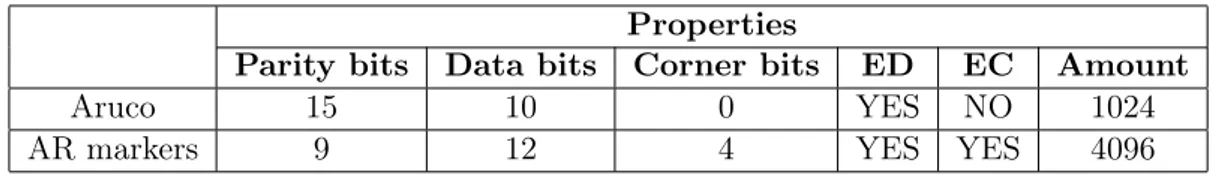
In [22], the author presents a new approach to encode, decode, and track 2D markers. The 2D markers are given a coordinate when extracted from an image. The coordinate system has an x- and y-axis with the origin being in the top left corner. Similarly to the Aruco library, described in section 2.4.1, the proposed solution AR Markers makes use of error detection algorithms to detect if bits are misinterpreted. The Aruco library uses 15 bits out of the 25 bits that a marker is composed of (5x5 matrix) to identify errors, but it does not have an algorithm for correcting found errors. This leaves 10 bits of actual data holding the unique identifier of the marker. Having more parity bits than data bits and only detecting errors without correcting them is a flaw in the Aruco algorithm, according to the author.
The alternative approach presented in [22] embeds a Hamming Code algorithm into the marker pattern. Using 3 parity bits and 4 data bits for every 7 bits in combination with er-ror correction leads to higher reliability for a more extensive set of unique markers. Further, the algorithm makes use of 4 bits placed in corners for identifying the marker orientation. A comparison between the Aruco Library and the proposed library can be seen in table 2 below.
Properties
Parity bits Data bits Corner bits ED EC Amount
Aruco 15 10 0 YES NO 1024
AR markers 9 12 4 YES YES 4096
Table 2: Comparison between the Aruco library and AR Markers library.
Comments
This study and the proposed algorithm is useful for this thesis when choosing a tracking library for the marker tracking subsystem. As seen in table 2 the AR Marker library uses its available data in a more efficient way.
3.2 Real-time 3D Human Pose Estimation with a Single RGB Camera
The authors develop real-time human pose estimation software for a single RGB camera [23]. They later compare their system with the Kinect as well as other methods used for estimating human poses. Overwhelmingly this seemingly simple setup, consisting of one camera, performs very well and at times even better than some of its counterparts. The authors use a convolutional neural network (CNN) for the predictions. Some mispredictions occurred, resulting in implausible 3D poses. The authors conclude that using only one camera affects the accuracy depth wise. Also, the implementation only predicts the pose
of a single person. The authors of this paper created the first method for estimating the kinematic pose of a human from a single RGB video stream at 30 Hz [23].
Comments
The paper is useful for this thesis as it presents a technique for estimating the kinematic pose of a human while using a single RGB camera. It also outlines the current limitations of this method, which useful in this thesis.
3.3 Computer Aided Board gaming using Computer vision
This thesis presents and implements an augmented reality board game using object tracking [2]. The object tracking is made possible by using computer vision techniques for tracking and interpreting the board game. The author then evaluates and analyzes the system by having end-users fill out a questionnaire. The author mentions that improvements can be made with respect to tag filtering, tag detection, pose estimation, and testing. The author concludes that augmented reality has the potential to be used in commercial products and has, as of when the thesis was published, only been used once commercially [2].
Comments
This thesis’ usage of real-time tag tracking is useful for this thesis as it can be compared with other techniques for solving the same problem. The author’s use of user testing is also useful while developing tests for this thesis.
3.4 Top-down Human Activity Analysis for Interactive Surface Appli-cations
In 2014, an article [24] exploring how surface-based computing could be integrated with the tracking of participants location, orientation, and actions relative to displays was pub-lished. The authors describe how a Kinect V2 can be used in a top-down fashion for human motion detection. Using a top-down detection method has two significant advan-tages, according to the authors. Occlusion disappears in many cases, and the tracking space increases when mounting the camera above the tracked area.
For validation of the system, the researchers apply their tracking system to two very dif-ferent interactive surface application contexts. One where participants collaborate around a table and another where participants interact with a kitchen exhibition.
Comments
The paper contributes to this thesis by presenting an alternative method for human body detection. It also explores how top-down tracking can be used for collecting data from interaction around a table.
4
Method
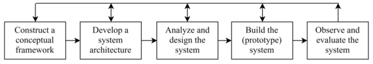
This section presents the method that is used for the development of the object tracking system. The research method is based upon the one proposed by Nunamaker et al. [25]. The iterative and systematic approach of this method has the potential to transform a concept into a prototype.
4.1 Nunamaker
The method that Nunamaker et al. propose consists of five steps [25]. Each step has a logical succession, from framing the research problem to testing it. The iterative nature leads to natural cycles and a back and forth motion between the subsequent steps within the method. Figure 5 demonstrates the structure of the method.
Figure 5: Overview of the Nunamaker method 5.
4.1.1 Construct a Conceptual Framework
The purpose of this stage is to formulate ideas about how the research questions can be solved. The research domain is explored to place the questions in an appropriate context. This stage involves the construction of a meaningful research question by investigating the functionality and requirements of the system. The problem is broken down into a problem tree to establish a better overview, as seen in section 5.1. Each sub-tree is then thoroughly described in section 5.1.2. A literature study is done to find related work toward object tracking. The related work is analyzed to find new approaches and ideas for answering the research questions as well as building the object tracking system.
4.1.2 Develop a System Architecture
Once the research questions are formulated, and the problem is broken down into sub-problems, the different sub-problems and their interrelations within the object tracking system are identified. The technical specifications and limitations of the system are consid-ered and incorporated when establishing the architecture. The system and its subsystems functionality, as well as a logical view of the system, is developed and shown in 5.2.
4.1.3 Analyze and Design the System
The designing of a system requires an understanding of the target domain. Extracting relevant technical knowledge is therefore done to dismiss inappropriate solutions early on. By doing so, time and resources are saved. The alternatives are then further specified and used as a blueprint for the implementation step in Nunamaker and Chen method. The result of this step is shown in 5.3.
4.1.4 Build the Prototype
Building prototypes is an efficient method for testing and validating ideas. Prototypes can be used to demonstrate the usability of the system’s functionalities. The acquired information from previous stages is used to implement a system. This implementation gives the authors insights into the system’s advantages and disadvantages. The insights are used when iteratively re-designing the object tracking prototype. This step in the Nunamaker and Chen method describes the software behind the object tracking system as well as the data format that is passed to subscribing MQTT clients. The result of this step can be seen in section 5.4.
4.1.5 Observe and Evaluate the System
Evaluation is first possible when the four first steps are complete. The last stage in the Nunamaker and Chen method involves testing the system and its subsystems. The expe-riences acquired from this step are used to develop the system through further iterations of the Nunamaker and Chen method. These evaluations can be found in 5.5.
5
Results
This chapter presents the results. They were produced by following the steps of the system development method described in chapter 4.
5.1 Constructing a conceptual framework
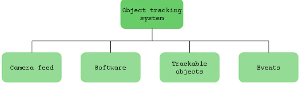
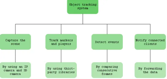
In this section, the object tracking system is divided into four subproblems as shown in figure 6. The subproblems are presented and briefly discussed below.
Figure 6: First layer of the problem tree.
• Camera feed: To be able to extract empirical data of player movement as well as 2D marker placement, the system has to capture the scene. Capturing the scene is done through image feeds using two cameras, one for tracking markers and another for tracking the player. Having two cameras, each with different hardware specifications and outputs, is a challenge. The camera feeds are the only input of the tracking system. The input data is dealt with asynchronously.
• Software: To track the objects, the system has to process and analyze image feeds. Having two cameras which are independent of each other, the different processing rates and output frequencies are taken into consideration when developing the system architecture. The system supports threading, which in turn enables the asynchronous feeds to be analyzed separately and in parallel.
• Trackable objects: The system tracks 2D markers and a single player. The 2D markers are identified by their position within the current 2D image. The player is sitting down by a table and identified by their upper body orientation within the current depth image.
• Events: As discussed in the background, the system is created for board games that meet the criteria presented in 1.3. Three types of 2D marker events and three types of player events are identified by analyzing valid moves in the game Dungeonquest [10]. These are presented in section 5.1.2 figure 10.
5.1.1 Literature study
A literature study is conducted to gather knowledge of how 2D markers and 3D cameras can be used for tracking objects to solve the problems shown in section 1.2.1. The more specific areas of concern being Kinect-based object tracking, marker-based tracking, and tangible user interfaces. IEEE Xplore and ACM digital library were the main databases used to gather information. A discussion of the related work gathered from the literature study can be found in section 6.3.
5.1.2 Problem breakdown
In this section the subproblems presented in section 5.1 are further broken down.
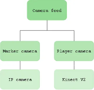
Camera feed:
The system makes use of two cameras as seen in figure 7. The cameras technical specifi-cations can be found in sections 5.3.2 and 2.2 respectively. How the cameras are mounted is presented in section 5.4.4 figure 19.
Figure 7: Camera feed subtree.
• Marker tracking using an IP-camera feed
To track the markers within the scene, an overhead camera is used. As seen in section 5.4, the camera is facing the table where the markers are located. The choice of camera is presented in section 5.3.2.
• Player tracking using a Kinect V2 feed
To track a player’s rotation, a Kinect V2 is used. The Kinect SDK provides function-alities such as joint detection. The joint detection is used by the system to calculate
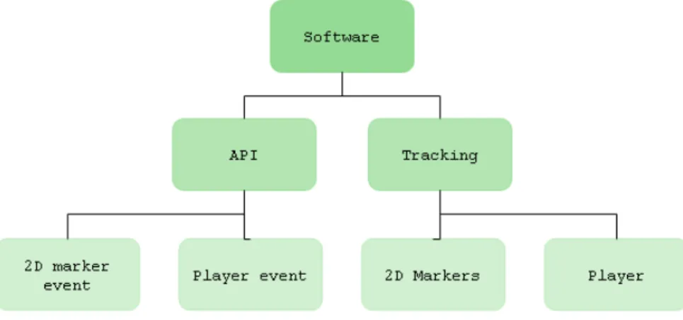
Software:
The software subtree that is seen in figure 8 consists of two distinct parts, the systems API as well as the tracking software. The software architecture is presented in section 5.4 alongside activity diagrams.
Figure 8: Software subtree.
• API:
The API is responsible for forwarding all events that have been detected to an MQTT broker. Clients that want access to the data subscribes to the MQTT broker. Clients are then able to receive the latest data from the tracking system. The choice of communication protocol is based on the limitations presented in section 1.3. MQTT is explained in chapter 2.
• Tracking:
The software is designed to take both cameras feeds as input, process it to detect events within the scene, and forward the events to connected clients. When choosing a tracking technique, third-party libraries for creating and detecting markers were analyzed. The chosen library for 2D marker tracking is presented in section 5.3.1. Third-party libraries for tracking player orientation follow the requirements presented in section 1.4 and considering those requirements the PyKinect2 library was chosen [26].
Trackable objects:
The system is set up to track two kinds of objects, as seen in figure 9.
Figure 9: Trackable objects subtree.
• Markers
The physical game objects that are subject to tracking are associated with a unique 2D-marker. The 2D-marker should be placed on top of the object and facing the overhead camera. The choice of markers is presented in section 5.3.1.
• Player
The player’s rotation is determined by tracking his/her shoulder joints.
Events:
The system is set up to detect two types of events, as seen in figure 10. These are de-tected by comparing consecutive frames from the video feeds. When a significant difference associated with one of the events is detected, an event has occurred.
• Marker events:
– Adding a marker to the scene
This event occurs when a new marker is introduced to the scene. – Removing a marker from the scene
This event occurs when a marker is no longer visible within the scene. – Moving a marker within the scene
This event occurs when a marker is moved within the scene. • Player events:
– Player rotation
Three body rotation events exist: Facing left, Facing table, Facing right. The rotation event is triggered when the absolute difference between the shoulder joints exceed 10 cm. The threshold of 10 cm was chosen arbitrarily, but is enough to separate a distinct change from just shifting position in the chair. The SDK used to retrieve joint data is described in 5.3.3.
5.2 Develop a system architecture
This chapter shows the functionality of the system as well as an illustration of how the subsystems are interrelated.
5.2.1 System functions
The system consists of four sub-functionalities as seen in figure 11.
5.2.2 Logical view of the system and API connectivity
By designing the general execution of the system as seen in figure 12, the foundation for sections 5.3 and 5.4 was constructed.
Figure 12: Logical view of the system.
• Camera feeds:
The IP camera is responsible for two things: Capturing the scene and broadcasting the feed to an IP-address. By using an IP-camera for retrieving an image, the software is not restricted to one particular camera. All following the requirements in section 1.4. The system receives the Kinect V2 feed through serial communication.
• The object tracking system:
This part of the system is responsible for the object tracking computations. These computations involve requesting the current frame from the IP camera as well as the Kinect, detecting if there has occurred events, and if so publish it to the MQTT broker. This repeats until the user terminates the program.
• MQTT Broker:
The MQTT Broker is responsible for receiving event data from the object tracking system and sending the event data to subscribing clients.
• Client(s):
Independent clients subscribes to the same topic that the object tracking system is publishing to. Once subscribed, they receive an event as soon as it is made available to the broker.
5.3 Analyze and design the system
5.3.1 Tracking technique and 2D marker design
There are various methods for tracking objects. How objects are identified is what differ-entiates the most between techniques. Tracking based on colors can be achieved, but this method is sensitive to changes in the environmental light. Tracking techniques can rely on tracking certain shapes. This would work poorly with cards of the same size. In regards to bar codes and QR-codes, the size of their patterns are small, which forces the camera closer to the tracked objects. This could get in the way of gameplay. Using trackable markers with larger square patterns enables the camera to be placed further away. Being limited to tracking cards, the 2D marker library AR Markers discussed in section 3.1 is suitable and was therefore chosen.
5.3.2 Choice of marker tracking camera
The requirement to be able to use any IP-based camera for the 2D marker tracking had to be considered when choosing a camera. Today, 67% of the world population has a mobile phone [27], and the majority of these devices have an embedded camera. With the possibility of using applications such as IP Webcam [28], the camera feed can be accessed from a remote computer. Using a mobile phone for capturing the table and its contents avoids the need to purchase an additional dedicated IP camera. The Samsung Galaxy S7 [29] is chosen as the marker tracking camera, and its specification can be seen in the table below.
Samsung Galaxy S7
Rear Camera Dual Pixel 12MP OIS (F1.7)
Processor Octa-core (2.15GHz Quad + 1.6GHz Quad) RAM 4GB RAM (LPDDR4)
OS Android
Table 3: Specifications for the Samsung Galaxy S7 [29].
5.3.3 Choice of player tracking camera and library
The Kinect V2 was used for player tracking, as mentioned in section 1.3. Other alternatives for depth sensing exist but few that are as cheap and readily available as the Kinect. Microsoft provides a powerful SDK for the Kinect V2 [30]. Through the SDK, 25 body joints can be extracted from a captured body as well as depth and color frames, audio, hand states, and facial expressions. However, this SDK only has support for C++ and C#. The chosen language for building the prototype was Python. Therefore a third party port of the code was used called PyKinect2 [26]. The PyKinect2 library provides a limited amount of method calls compared to Microsoft’s original development kit. Despite this, PyKinect2 includes what is essential for this thesis, namely body data. The body data includes the x, y, and z joint-coordinates of the detected body.
5.4 Build the prototype
In this section, the individual tracking algorithms are explained. Python was chosen as programming language mainly because it is easy to prototype with. Activity diagrams are included in this chapter to illustrate how the algorithms operate. A description is given of how the event data is published to the MQTT broker by using a common event queue that is handled by a dedicated worker. Finally, a description of how the individual subsystems are combined to a single system is explained.
5.4.1 2D marker tracking algorithm
When initializing the 2D marker tracking algorithm, the URL for the IP camera is pro-vided. The URL enables the program to access the latest frame from the camera. The AR Marker library presented in section 3.1 is then used to analyze and extract markers and place them in a list. It was discovered that at certain instances 2D markers would not be identified by the AR Marker library. Improvements towards the sensitivity of the marker library were therefore made by comparing 2D marker readings extracted from con-secutive frames. By reading five frames before the algorithm reaches the "Get camera frame" activity, the most common coordinate associated with each of the five 2D mark-ers is extracted, making the system more reliable. Using 5 frames corresponds to simple filtering of the image, to avoid triggering events from random changes in the camera image.
Once the current marker list is extracted, a comparison between the current marker list and the previous marker list is made. If the content of these two lists is the same, no events have occurred, and the algorithm starts over. If the lists differ, the differences are extracted and analyzed one by one. Every difference indicates that one of the three 2D marker events presented in figure 10 has occurred. The event Change is triggered if the 2D marker is in both of the lists but with different coordinates. The event Add is triggered if the 2D marker is only in the current list. Finally, the event Remove is triggered if the 2D marker is only in the previous list.
Image feeds of higher resolution lead to a more sensitive tracking of the 2D markers. It was shown that with a resolution of 1280x720 pixels, the marker tracking algorithm could identify the same marker on different locations even though the marker was stationary. This effect is further referred to as a floating effect. To separate actual 2D marker move-ments from those produced by the floating effect a test is conducted. It is necessary to find the maximum deviation that the floating effect produces. To find this deviation, a 2D marker is placed within the scene on five different locations, as seen in Appendix A figure 21. For every location, the overhead camera captures and analyzes 1000 images to extract the 2D marker’s location. Once the locations are extracted, the maximum de-viation is identified and used as a threshold for the 2D marker algorithm. As seen in Appendix A figure 22, the maximum deviation is identified to 1.41 pixels and means that a threshold of 2 pixels can be set to filter out actual 2D marker movements and when the event Change is triggered. For every difference between the current 2D marker list
Figure 13: Activity diagram for marker tracking algorithm.
5.4.2 Player tracking algorithm
Each frame is analyzed to detect if a body is present. In the case that no body is de-tected, the algorithm analyzes the next frame. If a body is present, a sequence of checks occur. The shoulder joints are retrieved using the SDK. The depth of the shoulder joints is compared and analyzed. This data is used to asses the rotation of the player. An event is only triggered if the current state differs from the previous state. When a new event is detected, the variable holding the previous rotation is set to the current rotation. The event_triggered flag is then set to True. Finally, the data is formatted as seen in figure 16 before being passed to the worker. The activity diagram illustrating player tracking is illustrated in figure 15.
5.4.3 Worker algorithm and publishing to the MQTT broker
The worker is responsible for publishing the event data that the two tracking algorithms detect. It does this via an MQTT broker. When initializing the worker, a connection is established to the MQTT broker. This requires the correct credentials found on the CloudMQTT website. The connection is retained until the worker is terminated. Fur-ther, a common event queue has to be set up. The python library Queue [31] is used as it supports multi-producer access meaning that it can be safely shared between parallel processes that try to access it simultaneously. The parallel processes in this context being the 2D marker subsystem as well as the player tracking subsystem. The activity diagram in figure 17 illustrates how the worker operates.
Once the MQTT connection and the queue have been set up, the worker enters a loop. For every iteration of the loop, the worker tries to dequeue from the queue. If the queue is empty, the program continues to the next iteration of the loop. Otherwise, an event is dequeued and processed. Processing an event involves ensuring that the event is correctly formatted to JSON and then publishing that event to a topic on the MQTT broker.
5.4.4 The system architecture
Having developed the three subsystems described in sections 5.4.1, 5.4.2 and 5.4.3 the com-plete system is assembled. Knowing that 2D marker events and player events are triggered asynchronously, it was decided to run them on separate threads. The same solution was established for the worker. To handle the data from the asynchronous camera feeds, it too had to be run on a separate thread. The system architecture and its independent threads are shown in figure 18. The system in action is seen in figure 19.
5.5 Observe and evaluate the system
This section presents the unit tests that were carried out to verify that the individual subsystems performed as expected. Lastly, the entire system is validated through a test sequence. All of the tests presented in Appendix B were conducted in a lab environment with even lighting.
5.5.1 Verifying the marker tracking subsystem
When testing the marker tracking subsystem the overhead camera is placed 0.86 m above the table as seen in figure 19. The distance to the table was chosen arbitrarily. With this configuration, the chosen camera presented in 5.3.2, was able to cover 108x60 cm of the table. This configuration can cover the test sequence found in figure 29 Appendix C. As stated in the limitations, the 2D markers are tracked by their pixel coordinate. This limitation leaves metric conversion and accuracy measurements of the marker tracking subsystem for subscribing clients. Appendix B figure 23 shows the test results.
5.5.2 Verifying the player tracking subsystem
When testing the player tracking subsystem, the Kinect V2 is placed 1.3m from the inter-acting player. Appendix B figure 24 shows the test results. The distance to the player was chosen arbitrarily. As long as the Kinect V2 covers the players upper body and is with-ing its workwith-ing range, which is presented in table 1 section 2.2, rotations will be detected properly.
5.5.3 Verifying the API
The API tests verify that the system could provide event data to connected clients. By setting up a program acting as a client, the worker subsystem was thoroughly tested. This client was set up to get notified whenever a new event occurred and print the event to the console. The basic functionality needed for a subscribing client is seen in Appendix C figure 27. Appendix B figure 25 shows the test results.
5.5.4 Verifying the object tracking system
Once the individual subsystems were thoroughly tested and verified, the entire system, which is presented in 5.4, was tested. Appendix B figure 26 shows the results of verifying the object tracking system.
5.5.5 Validating the object tracking system
The system was validated by mimicking a real scenario in a board game. This scenario involved placing, moving, and removing 2D markers on a table in a predefined sequence. Volunteers performed the sequence while the object tracking system was running.
Designing the system validation sequence
None of the data extracted during the validation process can be tied to a specific person. Despite this, a consent form was handed to and signed by all participants before their participation. Having a consent form is a GDPR requirement when it comes to processing personal data [32]. The consent form is seen in Appendix C figure 28.
When designing the test sequence for the system, it was essential to trigger all of the events at least once to make sure that they were registered correctly. After discussing with our supervisors, it was decided to give the volunteers as little information about the sequence as possible to see if events could be triggered naturally. One of them is to flip a 2D marker on the far left with their right hand to make them rotate left to make the move. The document containing the test sequence as well as an image from the overhead camera can be found in Appendix C figure 29.
Results from the system validation sequence
The system was validated by letting four participants perform the test sequence described above. They were informed to follow the five steps to ensure that they performed the same actions in the same sequence. The results of the system validation can be seen in Appendix C figure 30. In table 4, a summary of the results from the system validation is seen. The results of the validation tests are discussed in section 6.2.
Participant 1 Participant 2 Participant 3 Participant 4 Events
triggered Yes Yes Yes Yes
Performed in
expected order No No No No
6
Discussion
In this section, the research method, results and previous work are discussed
6.1 Building the prototype iteratively
By breaking down the process of building a prototype into several steps and working on each systematically, the prototype was built successfully. Due to the thesis limitations, the hardware for this project was set from the beginning and therefore, never subject to the iterative method. The software, on the other hand, was developed using the iterative system development method proposed by Nunamaker and Chen. By iterating twice, the prototype was developed. The first iteration being the two subsystems presented in sections 5.4.1 and 5.4.2 and the second being the integration of these together with the worker algorithm presented in section 5.4.3. By the time the second iteration was complete, the system, as well as the architecture presented in section 5.4.4, was finalized.
6.2 Analysis of results
The aim of this thesis was to collect empirical data from gameplay, and as such, the thesis has succeeded. There exist many techniques for collecting player and marker data, all with their respective advantages and disadvantages. One of the issues faced in this thesis was determining the amount of logic the system should handle. If the system is developed to handle game-specific rules, in this case the rules of Dungeonquest, this might limit the system to a specific game. After consideration, it was therefore decided that the system collects 2D marker and player data irrespective of context. With the hope that the usage of the techniques developed would not be limited to one scenario.
If the Egocentric Interaction research group (EI research group) decided to use the system in the game Dungeonquest certain aspects should be considered. To identify the position of the game board, one would have to place 2D markers on every corner. The 2D markers should not be placed on tiles as this could affect the gameplay negatively due to them cov-ering the content of the tile. How the 2D markers are currently designed to be integrated with Dungeonquest is seen in figure 20.
In Appendix B figures 23, 24, 25 and 26 verify that the subsystems, as well as the system in its entirety, performs as intended. The tests cover basic functionalities to ensure that the events are registered, that the subsystems can communicate with each other properly, and that the data sent from our system can be sent to and received by an MQTT broker. For any context other than a tabletop board game scenario, the system needs modifications. These modifications would require their own set of tests. The system would further have to be retested as a whole to ensure that the basic functionalities, some of them previously mentioned, still perform as intended. As mentioned in the summary table found in section 5.5.5, predicting the order of events in a test sequence involving different test participants is a challenge. Not surprisingly, each of the four participants performed actions in slightly different ways. What is important is that the system registered all of the expected events.
Figure 20: A scene from the game Dungeonquest with associated 2D markers.
6.3 Related work
The paper that closest resembles the work done in this thesis is Computer Aided Board Gaming using Computer Vision [2]. The results in the paper are based upon both quanti-tative and qualiquanti-tative measures, while this thesis verifies and validates the results through tests only. Furthermore, the author implements augmented reality on top of a marker tracking system and uses one camera to achieve that goal. In this thesis, we did not de-velop any augmented reality. Instead, the system combines marker tracking, similar to the mentioned paper, with body tracking. This was made possible by using two cameras instead of one.
The paper described in section 3.1 is also closely related to the work done in this thesis. The author identified and improved upon the weaknesses of another 2D marker library. The proposed 2D marker algorithm was essential for our implementation. Although the 2D marker library proposed by the author worked as a basis for this thesis work, further improvements had to be done as described in section 5.4.1.
The two papers Top-down Human Activity Analysis for Interactive Surface Applications [24] Real-time 3D Human Pose Estimation with a Single RGB Camera [23] provided insight and inspiration for the developed prototype. In both papers the Kinect is used for human pose estimation. One paper does so by capturing the scene from above. The other paper uses an RGB camera and using the Kinect to predict the same scenarios to compare the results with. These papers broaden the field and introduce new ways and alternative ways
7
Conclusion and future work
In this section, the research questions are answered, and possible future work discussed.
7.1 Answering the research questions
In section 1.2.1, the research questions for this thesis are presented. Below, the main research question and its subquestions are answered thoroughly.
• RQ1: How can empirical data be extracted from event-driven interaction around a tabletop board game?
– RQ1.1: How can asynchronous events be handled? – RQ1.2: How can event data be accessed by clients?
In section 5.2, the individual subsystems were integrated. Having two asynchronous image feeds as inputs, it was decided to handle them in parallel on separate threads. By doing this RQ1.1 is answered.
The API was limited to using the MQTT protocol from the start. However, the challenge of publishing the output from the individual subsystems sequentially remained. To en-able the system to publish events one-by-one a worker algorithm with a common queue, presented in section 5.4.3, was developed. Once the worker algorithm was developed and tested, clients could connect to a common topic on the MQTT broker which answers RQ1.2.
In sections 5.4.1 and 5.4.2 the algorithms that capture the event-driven interaction are described. One of the two subsystems is responsible for capturing 2D marker events and the other captures the events tied to a player’s rotation. The JSON formats presented in figures 14 and 16 are the outputs of the object tracking system. This answers the main research question, RQ1.
To answer the research questions, the system requirements presented in section 1.4 had to be fulfilled. How the system requirements were met is explained below.
1. The events should be formatted as JSON and made accessible via an API so that connected clients can receive event data.
The object tracking system formats events as JSON and publishes them to a topic on the MQTT broker. The clients that are subscribing to this topic are notified when new event data is made available.
2. A simple client should be developed and used for verifying that the event data is received correctly.
The code snippet in Appendix B figure 27 shows how a simple client is set up. The client subscribes to a specific topic to receive event data. Test results show that the client receives the correct data via MQTT.
3. Any IP based camera for tracking the 2D markers should be able to substitute the one proposed in section 5.3.2.
Having the 2D marker tracking camera feed available via a URL, the object tracking system can access it. As stated in the limitations, the camera feed should not be subject to any distortion. In particular cameras with fish-eye lenses will not be able to use the system. Further, resolutions below that stated in table 5.3.2 reduces the performance of the 2D tracking system.
7.2 Future work
In this thesis, we have used the Kinect V2 to a limited extent. Within the player tracking subsystem, the Kinect is only configured to identify a single players rotation. Despite the limited usage of the Kinect V2, we still believe that that we have proven that it can be used in combination with 2D marker tracking in order to form a more complex object tracking system. Further functionality and an increased amount of events can be added, especially within the player tracking subsystem. The Kinect V2, together with its SDK, can perform more than depth sensing. It has a microphone array which can be used to record conversations or programmed to use voice control. Sound positioning is another use case not explored in this thesis. Hand gesture recognition should be considered as a possible extension to the system. Also, facial recognition and facial expression analysis could be developed and added. Mounting the Kinect above the table should also be explored. This would both enlarge the area that the camera can analyze and possibly enable the system to track more players. Links to the source code for the object tracking system as well as a video is seen in Appendix D.
References
[1] Omar; Shah Mubarak Yilmaz, Alper; Javed. Object tracking. ACM Computing Surveys, 38(4):13–es, 2006.
[2] Lasse Farnung Laursen. Computer aided board gaming using computer vision. Master’s thesis, Department of Computer Science, Copenhagen University, 2010.
[3] Ivan E Sutherland. Sketchpad a man-machine graphical communication system. Simulation, 2(5):R–3, 1964.
[4] Ict facts and figures 2017.
https://www.itu.int/en/ITU-D/Statistics/Pages/facts/default.aspx. [Online; accessed 02-May-2019].
[5] Brad A Myers. A brief history of human computer interaction technology. interactions, 5(2):44–54, 1998.
[6] Lesley Xie, Alissa N. Antle, and Nima Motamedi. Are tangibles more fun?: Comparing children’s enjoyment and engagement using physical, graphical and tangible user interfaces. In Proceedings of the 2Nd International Conference on Tangible and Embedded Interaction, TEI ’08, pages 191–198, New York, NY, USA, 2008. ACM.
[7] Almukadi Wafa, Aljojo Nahla, and Munshi Asmaa. The use of tangible user interface in interactive system to learn about countries. International Journal of Emerging Technologies in Learning (iJET), 04(04):142, 2019.
[8] C.M et. al. Juan. Tangible cubes used as the user interface in an augmented reality game for edutainment. 2010 10th IEEE International Conference on Advanced Learning Technologies, Advanced Learning Technologies (ICALT), 2010 IEEE 10th International Conference on, page 599, 2010.
[9] T Pederson. Egocentric interaction research group.
https://www.mah.se/english/faculties/Faculty-of-Technology-and- Society/Department-of-Computer-Science/Research-areas/Egocentric-Interaction-research-group/, Nov 2018. [Online; accessed
27-April-2019].
[10] Wikipedia. Dungeonquest — Wikipedia, the free encyclopedia.
http://en.wikipedia.org/w/index.php?title=Dungeonquest&oldid=865200271, 2019. [Online; accessed 02-May-2019].
[11] Jichao Jiao, Libin Yuan, Weihua Tang, Zhongliang Deng, and Qi Wu. A
post-rectification approach of depth images of kinect v2 for 3d reconstruction of indoor scenes. ISPRS International Journal of Geo-Information, 6:349, 11 2017. [12] R. Nar, A. Singal, and P. Kumar. Abnormal activity detection for bank atm
surveillance. In 2016 International Conference on Advances in Computing, Communications and Informatics (ICACCI), pages 2042–2046, Sep. 2016.
[13] G. M. Behara and V. P. Chodavarapu. Towards autonomous surveillance in real world environments. In 2017 IEEE National Aerospace and Electronics Conference (NAECON), pages 23–28, June 2017.
[14] W. Zhao, R. Lun, C. Gordon, A. Fofana, D. D. Espy, M. A. Reinthal, B. Ekelman, G. Goodman, J. Niederriter, and and. A privacy-aware kinect-based system for healthcare professionals. In 2016 IEEE International Conference on Electro Information Technology (EIT), pages 0205–0210, May 2016.
[15] Kinect v2 introduction and tutorial.
https://www.slideshare.net/SugiuraTsukasa/kinect-v2-introduction-and-tutorial, November 2014. [Online; accessed 01-May-2019].
[16] M. Fiala. Artag, a fiducial marker system using digital techniques. In 2005 IEEE Computer Society Conference on Computer Vision and Pattern Recognition (CVPR’05), volume 2, pages 590–596 vol. 2, June 2005.
[17] S. Garrido-Jurado, R. Muñoz-Salinas, F.J. Madrid-Cuevas, and M.J. Marín-Jiménez. Automatic generation and detection of highly reliable fiducial markers under
occlusion. Pattern Recognition, 47(6):2280 – 2292, 2014.
[18] Syed Naeem Firdous, Zubair Baig, Craig Valli, and Ahmed Ibrahim. Modelling and evaluation of malicious attacks against the iot mqtt protocol. In 2017 IEEE
International Conference on Internet of Things (iThings) and IEEE Green
Computing and Communications (GreenCom) and IEEE Cyber, Physical and Social Computing (CPSCom) and IEEE Smart Data (SmartData), pages 748–755. IEEE, 2017.
[19] Information technology — message queuing telemetry transport (mqtt) v3.1.1. https://www.iso.org/standard/69466.html, Jun 2016. [Online; accessed
25-April-2019].
[20] The HiveMQ Team. Mqtt essentials part 3: Client, broker and connection
establishment. https://www.hivemq.com/blog/mqtt-essentials-part-3-client-broker-connection-establishment/. [Online; accessed
25-April-2019].
[21] Kristopher Sandoval. What is the difference between an api and an sdk?
https://nordicapis.com/what-is-the-difference-between-an-api-and-an-sdk/, 2016. [Online; accessed 01-April-2019].
[22] Max Brauer. A new approach to decode a black and white marker.
https://web.archive.org/web/20180104190717/http://iplimage.com/blog/approach-encodedecode-black-white-marker/, 2012. [Online; accessed
06-Mar-2019].
[24] Gang Hu, Derek Reilly, Mohammed Alnusayri, Ben Swinden, and Qigang Gao. Dt-dt: Top-down human activity analysis for interactive surface applications. In Proceedings of the Ninth ACM International Conference on Interactive Tabletops and Surfaces, ITS ’14, pages 167–176, New York, NY, USA, 2014. ACM.
[25] J. F. Nunamaker and M. Chen. Systems development in information systems research. In Twenty-Third Annual Hawaii International Conference on System Sciences, volume 3, pages 631–640 vol.3, Jan 1990.
[26] Vladkol. Pykinect2. https://github.com/Kinect/PyKinect2, 2015. [Online; accessed 07-May-2019].
[27] Number of mobile phone users worldwide from 2015 to 2020 (in billions). https://www.statista.com/statistics/274774/forecast-of-mobile-phone-users-worldwide/, 2019. [Online; accessed
21-Mar-2019].
[28] Pavel Khlebovich. IP webcam.
https://play.google.com/store/apps/details?id=com.pas.webcam&hl=sv, 2019. [Online; accessed 21-Mar-2019].
[29] Galaxy S7. https://www.samsung.com/global/galaxy/galaxy-s7/#!/spec. [Online; accessed 06-May-2019].
[30] Kinect for windows sdk 2.0.
https://www.microsoft.com/en-us/download/details.aspx?id=44561. [Online; accessed 01-April-2019].
[31] Queue — a synchronized queue class.
https://docs.python.org/2/library/queue.html. [Online; accessed 06-May-2019].
[32] General data protection regulation (GDPR). https://gdpr-info.eu/issues/consent/. [Online; accessed 01-May-2019].
Appendices
A Calibration
Figure 21: Overview of the floating marker test captured by the overhead camera. The camera resolution is 1280x720.
Figure 22: Results of the floating marker test. Every graph holds the data from 1000 2D marker readings.
B System verification
Figure 24: Player tracking tests.
Figure 27: Code snippet demonstrating the basic functionality needed to subscribe to a MQTT topic and receive data from the object tracking system.
D Resources
The Github repository which contains the source code for the object tracking system: https://github.com/nilssonfilip1996/ObjectTracking
A Vimeo video demonstrating the object tracking system: https://vimeo.com/339395694, password: object_tracking
![Table 1: Specifications for the Kinect V2 depth sensing camera [11].](https://thumb-eu.123doks.com/thumbv2/5dokorg/4061569.84194/11.892.207.692.539.667/table-specifications-kinect-v-depth-sensing-camera.webp)
![Figure 2: Different types of 2D markers [17].](https://thumb-eu.123doks.com/thumbv2/5dokorg/4061569.84194/12.892.359.533.648.811/figure-different-types-of-d-markers.webp)
![Figure 4: MQTT in the ISO stack [20].](https://thumb-eu.123doks.com/thumbv2/5dokorg/4061569.84194/13.892.325.566.390.511/figure-mqtt-in-the-iso-stack.webp)