School of Innovation, Design and Engineering
Department of Information Engineering, Computer Science and Mathematics
A model-based safety analysis approach
for high-integrity socio-technical
component-based systems
Master Thesis for the Degree of Master of Science in Computer ScienceMaster student:
Edin Sefer (esr13004@student.mdh.se)
Supervisors:
Barbara Gallina, Mälardalen University, Sweden (barbara.gallina@mdh.se) Henry Muccini, University of L’Aquila, Italy (henry.muccini@univaq.it)
Examiner:
Kristina Lundqvist, Mälardalen University, Sweden (kristina.lundqvist@mdh.se)
2
Abstract
Designing high-integrity socio-technical systems requires a thorough understanding of all safety risks of such systems. For many years, safety risk assessment has been conducted separately for hardware, software, human, organizational and other entities in socio-technical systems. Safety risk assessment that does not consider all factors at the same time cannot adequately capture the wide variety of safety risk scenarios that need to be considered.
This thesis proposes a model-based analysis approach that allows interpretation of humans and organizations in terms of components and their behavior in terms of failure logic. The proposal is built on top of the tool-supported model-based failure logic analysis technique called CHESS-FLA. CHESS-FLA supports the analysis of the component-based system architectures to understand what can go wrong at a system level, by applying failure logic rules at a component level. CHESS-FLA addresses only hardware and software components and as such it is inadequate for the analysis of socio-technical systems.
This thesis proposes an extension of CHESS-FLA based on the preexisting classification (developed within SERA), of failures of socio entities. This extension combines CHESS-FLA and SERA - classification and delivers an approach named Concerto-FLA. Concerto-FLA is fully integrated into the CONCERTO framework allowing an automated analysis to be performed on architectures that contain human, organizational and technical entities present in socio-technical systems.
The use of the approach is demonstrated on a case study extracted from the petroleum domain. The effectiveness of the delivered tool is briefly evaluated based on the results from the case study.
3
Acknowledgments
First of all, I would like to express my deep gratitude to my supervisor at Mälardalen University, Barbara Gallina, for her precious suggestions, guidance, patience and limitless support during the entire thesis period.
Also, specials thank to my supervisor at University of L’Aquila, Henry Muccini, for his constructive comments and generous support throughout my thesis work.
I would like to thank Atle Refsdal for his valuable expertise from petroleum domain offering consultations, constructive discussions and industrial examples for this thesis.
Furthermore, sincere thanks to GSEEM project, especially coordinator Henry Muccini, for allowing me to study at two respectable universities such as University of L’Aquila and University of Mälardalen, offering me to enjoy student life at two wonderful cities, L'Aquila and Västerås.
Also, I would like to give a special thanks to European Commission and EUROWEB project for their generous financial support during my master studies.
Special thanks to my wife Elsada, who always stood by me and constantly strengthened me to believe in dreams and to live dreams. Without her, I would never reach so far.
Last but not least, special thanks to my family for given support and hope during this challenging experience.
4
Contents
1. Introduction ... 7 1.1. Motivation ... 7 1.2. Context ... 7 1.3. Contribution ... 7 1.4. Document organization ... 82. Background and related work ... 9
2.1. Dependability and safety ... 9
2.1.1. Preliminary concepts ... 9
2.1.2. Dependability and its threats ... 9
2.1.3. Dependability means ... 11
2.2. Component-based reasoning ... 11
2.2.1. Basic concepts ... 11
2.2.2. Component model ... 12
2.3. Model-driven architecture ... 13
2.3.1. Model transformation types ... 14
2.4. CONCERTO framework ... 15
2.4.1. Separation of concerns in CONCERTO ... 15
2.4.2. CHESS-FLA ... 16
2.4.3. Acceleo model transformation engine ... 18
2.4.4. Acceleo MTL ... 18
2.5. State-of-the-art of tool-supported techniques for modelling and analysis of failure behavior of component based architectures ... 21
2.6. Socio-technical systems ... 21
2.6.1. State-of-the-art of the risk assessment techniques ... 22
2.6.2. Systematic Error and Risk Analysis ... 26
3. Petroleum domain-related system ... 30
4. Scientific method ... 31
5. Problem formulation and analysis ... 32
5.1. Problem formulation ... 32
5.2. Problem analysis ... 33
5
6.1. Modelling support for failure behavior within socio-technical systems ... 35
6.1.1. What should be modeled? ... 35
6.1.2. Which socio entities should be modeled? ... 35
6.1.3. Which existing approach should be used as a basis for modelling of failure behavior of socio entities? ... 36
6.1.4. Which technique for analysis of failure behavior should be used? ... 39
6.2. Proposed solution – Concerto-FLA ... 40
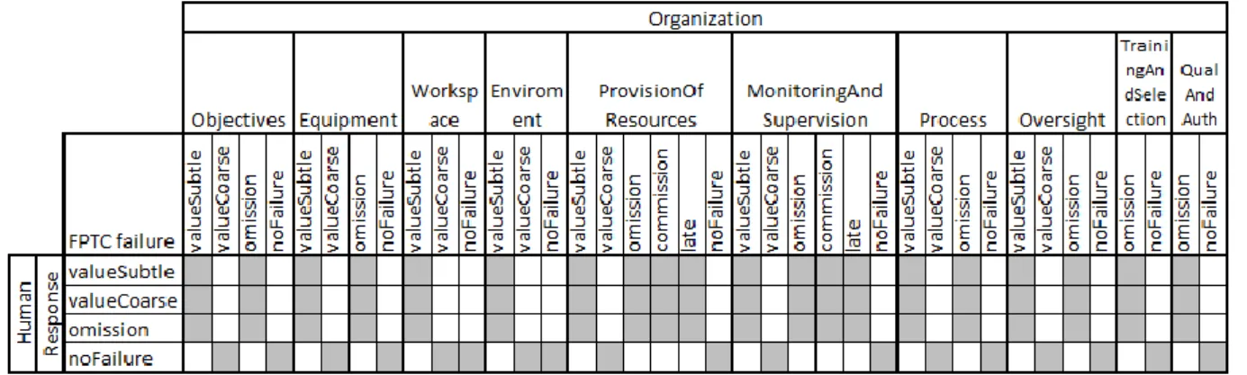
6.3. Failure types that characterize the failure behavior of socio entities... 44
6.3.1. Organizational preconditions in terms of CHESS-FLA FPTC-failure types ... 44
6.3.2. Human preconditions in terms of CHESS-FLA FPTC-failure types ... 46
6.3.3. Human failures in terms of CHESS-FLA FPTC-failure types ... 47
6.4. Automated fine grained analysis of failure behavior of socio-technical entities ... 54
6.4.1. Proposal for extensions in CONCERTO-ML ... 54
6.5. Integration of the proposed solution into the CONCERTO tool-set ... 55
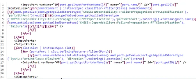
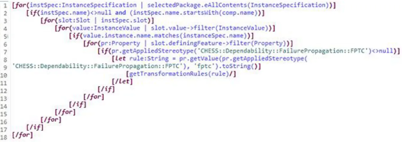
6.5.1. Updates of M2T transformation ... 55
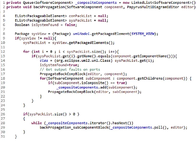
6.5.2. Update of backpropagation of analysis results ... 58
7. Case study ... 60
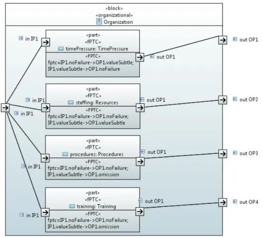
7.1. Modelling of the case study ... 60
7.1.1. Modelling internal structure organizational composite block ... 61
7.1.2. Modelling internal structure human composite block ... 62
7.2. Modelling of failure behavior and automated failure behavior analysis ... 63
7.3. Discussion ... 67
8. Conclusion and future work ... 69
8.1. Summary ... 69
8.2. Limitations and future work ... 70
References ... 71
6
Acronyms and Abbreviations
AEB Accident Evolution and Barrier Function AADL Architecture Analysis and Design Language C2S Command, Control and Supervision
CIM Computationally Independent Model
CONCERTO Guaranteed Component Assembly with Round Trip Analysis for Energy Efficient High-integrity Multi-core Systems
Concerto-FLA CONCERTO - Failure Logic Analysis
CHESS Composition with guarantees for High-integrity Embedded Software components aSsembly
CHESS-FLA CHESS - Failure Logic Analysis FRAM Functional Resonance Accident Model HERA Human Error in Air Traffic Management
HFACS Human Factors Analysis and Classification System
HiP-HOPS Hierarchical Performed Hazard Origin and Propagation Studies
MDA Model-Driven Architecture
MDE Model-Driven Engineering
PIM Platform Independent Model
PSM Platform Specific Model
M2M Model-to-model transformation
M2T Model-to-text transformation
MTO Man-Technology-Organization
RCA Root Cause Analysis
SERA Systematic Error and Risk Analysis
STAMP System-Theoretic Accident Model and Processes
STS Socio-technical systems
7
1. Introduction
This chapter represents the thesis introduction which is organized as follows: Section 1.1 describes the motivation for the thesis. Section 1.2 presents the context in which the thesis is defined. Section 1.3 presents the contribution of the thesis and Section 1.4 describes briefly the structure of the thesis.
1.1. Motivation
Work procedures on the offshore petroleum installations (called rigs) often involve safety-critical operations whose failure could cause accidents with serious consequences in terms of hazards to human life, property and environment. Such systems, which involve safety-critical operations, are called high-integrity systems [1] which include socio-technical systems (STS) as well. To keep these systems safe, it is necessary to identify what may go wrong and the way in which this can happen. This represents the essential part of the safety risk assessment and accident prevention. Accident analysis and investigation results showed that in almost 80% [2] of the cases a root cause for accidents in high-hazard industries is the human factor. However, human error occurs in conditions created by organization and environment. Focusing only on one of the contributing factors will not adequately capture all possible scenarios. Therefore, it is necessary to understand interrelatedness of all playing factors and identify the risks in STS.
1.2. Context
This thesis is defined in the context of the CONCERTO (Guaranteed Component Assembly with Round Trip Analysis for Energy Efficient High-integrity Multi-core Systems) [3] project, that strives to provide a multi-domain architectural framework that allows engineers to address dependability concerns, with special focus on safety. The attention of this thesis is limited to the modelling and analysis of safety-critical socio-technical systems. More specifically, within the CONCERTO, the failure behavior related to humans, organizations and technology shall be modelled and the eventual propagation of failures shall be analyzed. One of the supported domains that define the context of this thesis is the petroleum domain.
1.3. Contribution
The contribution of the thesis is related to the modelling and analysis of the failure behavior of socio-technical systems. The current state-of-the-art shows a lack of the tools and techniques for the joint modeling and analysis of failure behavior of socio-technical systems. This thesis contributed to the CONCERTO toolset by developing a method named Concerto-FLA. The novelty of the contribution is that Concerto-FLA permits architects to interpret humans and organizations in terms of composite components, and their behavior in terms of failure logic. Expression in terms of failure logic allows using the existing failure behavior
8 analysis algorithm in CONCERTO tool-set. The Concerto-FLA represents an evolution of the CHESS-FLA towards support for the analysis of socio-technical systems. This evolution is based on the existing failure classification for socio entities found in SERA approach, combined with the already used failures for technical entities in the CHESS-FLA. Built on top of the Model-Driven Engineering (MDE) premises, the Concerto-FLA uses model-to-text transformations to extract information about failure behavior from models and transform it into the form suitable for failure logic analysis. Moreover, as a result of an early work on this thesis, a paper [5] has stemmed from this thesis and it was presented at 2nd International Workshop on Risk Assessment and Risk-driven Testing (RISK 2014).
1.4. Document organization
Chapter 2 presents the background that is needed for a better understanding of the problem. Concepts presented in this chapter are also used to build the proposed solution in Chapter 5. Chapter 3 presents the petroleum domain related example that serves to demonstrate the use of the proposed Concerto-FLA.
Chapter 4 presents the scientific methods used in this thesis to find a solution to the addressed problem.
Chapter 5 describes the problem formulation and analysis. The main problem is described in details, divided into smaller subproblems, where each of them is covering a certain aspect of the main problem.
Chapter 6 describes the steps on how existing approaches might be used to solve the identified subproblems. Available approaches are compared and their limitations and advantages are presented with respect to their applicability to the presented sub-problems. A solution to the identified problem is proposed. Chapter 6 also shows how the selected approach is interpreted in terms of the CONCERTO framework and how it is integrated in the CONCERTO tools-set. Chapter 7 shows the applicability of the implemented solution on a case-study from the petroleum domain, presented in Chapter 3.
Chapter 8 contains the summary and the possible future work related to the results of this thesis.
9
2. Background and related work
This chapter provides background that helps in better understanding the content of this thesis. It starts with concepts and terms related to the system dependability and safety in Section 2.1. Section 2.2 describes system decomposition in a light of component-based reasoning in software engineering. Section 2.3 describes model-driven approach in architecting systems using model transformations. Section 2.4 introduces reader to the CONCERTO framework and related techniques. Section 2.5 presents the state-of-the-art of approaches that delivered accident models. Section 2.6 is devoted to socio-technical systems and model-based approaches for risk assessment of such systems.
2.1. Dependability and safety
This section is divided into three subsections: Subsection 2.1.1. recalls preliminary definitions needed to understand dependability; Subsection 2.1.2. recalls the definitions of dependability and describes the threats that can affect dependability, while Subsection 2.1.3 presents the general classification of dependability means. This Section is mainly based on [6].
2.1.1. Preliminary concepts
Prior to recalling the concept of dependability, it is necessary to recall the concept of correct service. This subsection recalls definitions of preliminary concepts such as system, its environment, and the service that this system offers.
A system is defined as any entity that interacts with its environment.
Environment of the system is again a system that can be hardware, software, humans or a physical world.
The system acts as a provider that delivers the services to its users or environment. Therefore, a system behavior, seen from a perspective of its users, represents the delivered service.
If a system performs well and if it implements system functions as described in the system functional specification, then it is delivering the correct service.
2.1.2. Dependability and its threats
To rely on a system and to become dependable on a system’s functionality a user expects to receive a service that has certain characteristics. In other words, a user has to trust that the system is going to deliver the correct service.
Dependability is defined as the “ability to deliver the service that can justifiably be trusted”. [6] Another definition of dependability is the “ability to avoid service failures that are more frequent and more severe than is acceptable”. [6]
10 From a user’s point of view, in order to be dependable, a system is expected to have the following attributes: availability, reliability, safety, integrity, and maintainability. Depending on the system nature and specification, not all dependability attributes are relevant for all systems. In order to make systems dependable, system architects must know the threats to the dependability and in which way to cope with these threats.
Faults, errors and failures represent threats to dependability. They are making a linear chain in which activated faults are causing the errors (see Figure 1). Errors can be propagated to the failures and a failure can cause a fault in another component or system.
According to [6], a fault is adjudged or hypothesized cause of an error.
Figure 1 - The fundamental chain of dependability and security threats [6]
Faults can be in active or in dormant state, where only activated faults can cause an error and the remaining faults stay in dormant state. Faults can also be internal or external of the system. For an external fault to happen, there must be an internal fault that enables external faults to cause an error.
By activating a fault, a transition from a valid system state to an erroneous state is performed. An error is a state of the system that may lead to failure to deliver a correct service.
By performing corrective actions, a system can transit from an erroneous state back to the valid state, making the service failure never happen. All these transitions are performed inside the system, transiting between the internal states.
A failure is an event that makes the system transit from an internal erroneous state to an erroneous state that can be perceived from the user.
The ways in which a service can deviate from the correct service represent failure modes of a service.
Failure modes are an interesting field of research for engineers since they do not only describe a possible set of service failures, but also provide a direction for taking necessary actions in making a system more dependable. Failure modes can be seen from four main viewpoints relevant for one safety engineer: failure domain, detectability of failures, consistency of failures and consequences on the environment.
Failures that can rise from the domain viewpoint can be put in three categories:
Content failure - the delivered content deviates from the specified content to deliver a system function. Content can be expressed by numerical and alphabetical sets.
11 Timing failure - arrival time or duration of the delivered information deviates from the specification to deliver the correct service. Timing failure can manifest as early or late, depending whether the information is delivered too early or too late.
Content and timing - combined together, these two failures can be classified as halt failures (occurs when a system is halted and has constant external states including no service at all) and erratic failures (occurs when service is not halted, but provides erratic information).
2.1.3. Dependability means
In order to make a system that can be justifiably trusted to deliver a correct service, various tools, methods and solutions are developed. They help architects at coping with dependability threats. These tools, methods and solutions are called dependability means and they are classified as follows:
fault prevention - focuses on the analysis and adaptation of the development process to reduce possible introduction of faults;
fault tolerance – focuses on the implementation of techniques to detect faults and recover a system by making it transit from an erroneous state to an error-free state; fault removal - focuses on performing techniques to detect and remove faults in the
development and use phase;
fault forecasting – focuses on providing techniques to evaluate system behavior to estimate present and future faults, and to determine their consequences.
This thesis aims to contribute in delivering a fault forecasting technique that helps engineers in identifying the things that may go wrong and the way in which they can go wrong within the socio-technical systems.
2.2. Component-based reasoning
In this section, concepts of the component-based engineering such as component, interface and connector are recalled. The section is organized as follows: basic concepts are presented in Subsection 2.2.1; Subsection 2.2.2 describes the component models and its elements. 2.2.1. Basic concepts
Due to the increasing complexity of the modern systems, system decomposition is used to break a system into smaller building blocks called components. The definition of a system, which was recalled in Subsection 2.1.1, implies that a system can be any entity that interacts with its environment, and therefore a system can be composed of components of different types. Computer systems are typically composed of software and hardware components. A software component can be defined as follows:
“A software component is a unit of composition with contractually specified interfaces and explicit context dependencies only. A software component can be deployed independently and is subject to composition by third party.” [7]
12 As the above definition states, a component is a unit of composition. Therefore it has to be well-specified and have predictable behavior to enable composition with the other components and integrate it into a system.
“Component composition is the process of integrating components with each other, and with specially written 'glue code' to create a system or another component. “ [8]
The component composition is achieved by using interfaces and connectors between those interfaces. A connector defines the information flow between components. An interface is defined as follows:
“Interface can be defined as a specification of component's access point.“ [9]
Interface only specifies the possible ways of the component usage by exposing the operations that can be used, but offering no implementation of these operations. This allows the change of the component implementation without changing the interface and affecting the environment of the component.
The component can have two general types of interfaces:
Exported interface - when the component provides a service to the environment; Imported interface - when the component requires a service from the environment to implement a service.
Unfortunately, interfaces are exposing only functional properties of the component through signatures, while extra-functional properties of the component remain hidden and need to be examined either via credentials or by the analysis of documentation.
2.2.2. Component model
Component models have risen from the need to standardize the way of specifying components and its characteristics. One of the general definitions of component model is:
"A Component Model defines standards for (i) properties that individual components must satisfy and (ii) methods, and possibly mechanisms, for composing components." [10]
However, many domains have specific requirements to achieve system properties such as real-time and dependability. The general purpose component models cannot be applied on such domains, which led to the existence of many domain specific component models. Domain specific component models incorporate component-based principles with the domain requirements.
13
2.3. Model-driven architecture
Model Driven Architecture (MDA) is a set of tools and standards that guide system architects in developing robust architectures by separating business logic from the details of the implementation technology. MDA is a subset of a broader concept called Model Driven Engineering (MDE) [11]. Even though CONCERTO is based on the MDE premises, it also implements the MDA principles and structuring of the system models. Therefore, the attention of this thesis is limited on the MDA, also because the main contribution of the thesis is more visible if it is placed into the context of the models and transformations in the MDA.
MDA “unifies every step of the development of an application or integrated suite from its start as a Platform-Independent Model (PIM) of the application business functionality and behavior, through one or more Platform-Specific Models (PSMs), to generated code and a deployable application.” [12]
MDA recommends three abstract models to be created: CIM (Computation Independent Model), PIM (Platform Independent Model), and PSM (Platform Specific Model).
CIM is a model that is computationally independent and includes domain specific abstractions used in a system. It does not discover the details about system structure, or how the system functionality is realized through model or artifacts.[13]
“PIM is a model with a high level of abstraction that is independent of any implementation technology.” [14]
PIM model has a certain degree of platform independence that fits many similar platforms. It shows computational components and their interactions without implementation related details, allowing generating various PIMs. PIM allows managing the application logic across all platforms, since implementation details are separated from the application logic.
“A PSM is any model that is more technology specific than a related PIM.” [13]
PSM is the result of the transformation applied on PIM model. Model transformation is a technique that has many practical applications in automating tasks in software development process and it is defined as follows:
Model transformation means performing a set of rules defined in transformation specification to convert source model or artifact into a target model or artifact.[13, 14]
Transformation specification defines rules for mapping source representation into target representation. In turn, transformation rule defines how source building elements should be transformed into target elements.
Therefore, PIM to PSM transformation contains additional information that enriches the PIM model with platform specific data and produces a PSM model. Each PSM corresponds to one
14 specific platform, and if PSM is detailed enough, it allows code generation from model. The contribution of this thesis is placed into the context of PIM, taking it as a source model for the safety analysis and risk assessment.
2.3.1. Model transformation types
In model-driven approach, all models, which include a transformation as well, conform to the appropriate metamodels, thus a transformation, source, and a target models conform to their metamodels. A transformation model is defined as a set of transformation rules. The transformation process begins when the transformation rules, expressed using the transformation language, are interpreted by the transformation engine. Then, the transformation engine applies these rules on elements in the source model in order to produce a target model.
In general, it is possible to distinguish the following transformation types and associated technologies [15]:
Model-to-model (M2M)
In the model-to-model transformation type, the transformation engine takes a model as an input, and produces a model as an output. M2M transformations are used to generate different system views for desired viewpoints by hiding information from the source model or enriching the source model with new information. The source code written in programming language can be seen as a model, where metamodel is defined by programming language rules. A good example of M2M transformation can be found in the MDA software design approach, in which PSM is generated from PIM by enriching PIM with platform specific information. Many M2M transformation languages and engines exist today and here is a short list of some of them: EMF, ATL, QVT, Smart QVT, ETL, etc.
Model-to-text (M2T)
In model-to-text transformation type, the transformation engine takes a model as an input, but, instead of a model, as an output produces a text that can be code, text, document or any other form that is not a model. It does not require any metamodel for the output file. M2T is usually used to speed-up software development process, more specifically, to generate code or text, i.e. documentation, from platform specific models. It is necessary to specify transformation for each programming language, or for each desired output text format. Some of the M2T transformation engines existing today are: xText, Acceleo, JET, Xpand, EMF text, Kermeta, MOF script, etc. This thesis uses Acceleo M2T transformation engine to extract extra-functional properties from PIM models on different levels of abstraction. Acceleo is described in more details in Subsections 2.4.3 and 2.4.4.
Text-to-model (T2M)
In text-to-model transformation type, the transformation engine takes a text as an input, and produces a model as an output. T2M is usually used to extract models and metamodels from a
15 textual representation in order to perform a more complex operation on extracted models. Some of the T2M transformation engines are: EMF text, xText.
2.4. CONCERTO framework
This section introduces reader to the CONCERTO framework and related techniques. The section is organized as follows: Subsection 2.4.1 presents and briefly explains separation of concerns in CONCERTO. Subsection 2.4.2 presents CHESS-FLA as a tool within CONCERTO framework. Subsection 2.4.3 presents Acceleo model transformation engine used in the implementation of CHESS-FLA. Subsection 2.4.4 presents the syntax and use Acceleo modelling language.
As it is stated in the Chapter 1, this thesis is defined within a framework of the CONCERTO project [3]. The work product of the CONCERTO project is the CONCERTO tool-set that has a goal to enhance the CHESS component model to support multi-domain component models, operation modes, and to broaden support for separation of concerns towards a multi-domain environment. The CHESS tool-set is implemented as a set of Eclipse plug-ins that forms a model-driven engineering infrastructure for congregation of high integrity component-based systems. Following the MDA standard, systems are designed through several model-transformations starting with the creation of PIM using the modelling language CHESS-ML. The PIM model is then enriched with platform specific data which allows automatically performing the transformation and generating the PSM model. Finally, a code can be automatically generated from the PSM models. Additional model transformations and a back-propagation mechanism can be used to analyze the models and to guarantee that models and their implementation satisfy the desired extra functional properties.
2.4.1. Separation of concerns in CONCERTO
Architecting of the system using the CONCERTO design process is organized through several multi-level design views. Each view addresses one or more stakeholders and their concerns. In that way, separation of concerns is achieved, by exposing in each view characteristics interesting for stakeholders. At the moment, a CONCERTO environment has the following top level design views:
System views - allows the system engineer to model the user context, business concepts, use-cases, scenarios, product lines variability, analysis and of course the overall, top level system design.
PIM views - represent a set of platform independent views used for the development of the multi-concern component-based architectures. It consists of the following sub-views:
o Component view is used for the modelling of software components. This view is composed of two sub-views: Functional and Extra Functional views. Functioanal view allows specification of functional properties of the components. Components are connected using client-server ports, which are also used to expose previously defined, provided or required interfaces and
16 data types. In Extra Functional view a user can specify extrafunctional properties of components such as dependability. Information specified in this view can be used in Analysis view to calculate extrafunctional properties. o Instance view – allows designers to perform specification or refinement at
instance level. It focuses on instance model which can be automatically derived using information present in composite diagrams.
Deployment view allows the creation of the mandatory target execution platform. This view is composed by the following sub-views: the Platform Specification View, the Allocation View and the Dependability View. Platform Specification View allows the specification of the hardware platform entities. The Allocation View allows designers to allocate the software component instances to the hardware instances which can be enriched with dependability attributes inside Dependability View.
Analysis view allows definition of behavior of the element instances that will be used in the context of the input for one of the available analysis tools. The analysis view is composed of two sub-views: Dependability view (addresses dependability properties of the system) and RTAnalysis view (addresses real-time system analysis).
PSM views – owns the automatically generated entities related to the target computational model. These entities implement component's extra functional constraints defined in PIM. The entities in the PSM View are read-only and can be navigated in the CONCERTO editor by using a tree-like model explorer.
Requirements view allows modeling and tracing functional and extra-functional, software and hardware requirements and connecting them to the model entities like component implementations.
2.4.2. CHESS-FLA
This subsection is partially based on [5], that presents initial results connected to this thesis work. CHESS-FLA[27] is a plugin within the CHESS tool-set that allows safety engineers to perform an early based safety analysis on high-level models (PIM). It allows decoration of component-based architectural models with dependability related information which then serves as a basis for the Failure Logic Analysis (FLA) techniques such as FPTC [28] and FI4FA [29]. The analysis results are then back-propagated into the original model. CHESS-FLA supports the analysis of architectures composed of hardware and software components. This thesis focuses on the FPTC (Failure Propagation Transformation Calculus) analysis technique that allows qualitative dependability analysis of the component-based systems in terms of failure propagation and transformation calculus.
The FPTC analysis calculates system behavior based on the specified behavior of its internal components. Therefore, each component has to be examined in isolation to determine its behavior, nominal as well as faulty. A component can act as a source (due to the activation of internal faults, the component generates a failure in output) and as a sink (detection and correction of the input failure). Furthermore, a component can propagate the failure (failure is propagated from input ports to the output ports) and also transform the failure (the nature of the failure has changed and sent on output port). The FPTC failure behavior of the individual component is specified as a set of logical rules expressed as combinations of input failures
17 (occurring on input ports) with the output failures (occurring on output ports). CHESS-FLA has adopted the following syntax to specify the behavior of the component:
behavior = expression+ expression = LHS ‘’ RHS
LHS = portname‘.’ bL | portname ‘.’ bL (‘,’ portname ‘.’ bL) + RHS = portname‘.’ bR | portname ‘.’ bR (‘,’ portname ‘.’ bR) +
failure = ‘early’ | ‘late’ | ‘commission’ | ‘omission’ | ‘valueSubtle’ | ‘valueCoarse’ bL = ‘wildcard’ | bR
bR = ‘noFailure’ | failure
The failure modes recalled in Subsection 2.1.3 are further expanded in CHESS-FLA FPTC and can be categorized as follows [19]:
Value (content) related failures:
o valueSubtle – “The output deviates from the expected range of values in an un-detectable way (by the user)” [29]
o valueCoarse – “The output deviates from the expected range of values in a detectable way (by the user)” [29]
Time related failures:
o early – an output provided earlier than expected o late – an output provided later than expected Provision (content and time) related failures:
o omission – no output is provided
o commission – an output is provided when not expected.
It is important to highlight that valueCoarse is in general detectable by humans and they can perform corrective actions and stop further failure propagation. An example of a FPTC compliant expression is:
R1.noFailureP1.valueCoarse
The above transformation rule is interpreted as follows: if the component receives on its port R1 a ‘noFailure’ which means a normal behavior, it generates on its output port P1 a ‘valueCoarse’ (i.e. value failure detectable by humans).
Connected components are considered as token-passing network in which a system-level behavior is calculated via fixed-point calculation that calculates the maximal-tokenset on any connection in the network. The FPTC technique combines two traditional risk identification techniques (i.e. Fault Tree Analysis and Failure Modes and Effects Analysis) often recommended by safety standards. CHESS-FLA uses ACELEO engine to perform M2T transformations for extracting information about components, ports, connections and the transformation rules. The coproduct of the transformation is XML file which is used as an input to the analysis. It is important to highlight that current CHESS-FLA does not distinguish component types at XML level. Analysis results are also stored into XML file which is then parsed and used for backpropagation of the analysis results.
18 2.4.3. Acceleo model transformation engine
Acceleo[16] is a M2T transformation tool, developed by Obeo company, whose primary purpose is code generation. It takes any MOF model and a corresponding metamodel as inputs to generate text. Acceleo model transformation engine has been built on top of the OMG MOF Model-to-text specification [17]. It is a part of the Eclipse IDE standard edition and allows code generation from most model types. Acceleo transformations can be run inside Eclipse IDE, but a great advantage of Acceleo is that it can be run as a standalone application. Transformations can be run in background. Hence the end user does not have to know if the Acceleo is used in Eclipse plugin implementation. It is used as a transformation tool in CHESS and as well in CONCERTO. The Acceleo tool is supported by the Acceleo Model Transformation Language (MTL) which is described in details in Subsection 2.4.4.
2.4.4. Acceleo MTL
Acceleo generator is composed of modules declared in .mtl file. Acceleo transformations are written in MTL language. The .mtl file structure begins with module declaration and specification of the metamodels for input models in form:
[module <module_name>('metamodel_URI_1', 'metamodel_URI_2')/].
A module can extend and import another module and access its public elements. The Acceleo module contains templates, which are generating code, and queries, used for complex expressions. Coding is intuitive and allows plain text, which will be contained in output files, to be mixed with the Acceleo code and rules. Acceleo code consists of the expressions, that can be defined as blocks or inline expressions. Blocks start with [name_of_block] and ending with [/name_of_block], while inline expressions are defined in one line and look like [expression /].
After module declaration, a template is defined with the root element, delimited by [template...][/template] tags. Acceleo transformations are implemented as a set of rules declared inside a template. Rules are matched against a source model in order to generate the output. Templates are the most important constructs in Acceleo since they are giving instructions to the generator while generating the output. They are defined by the template visibility (similar to the visibility in object oriented programming), template name and parameters. There are two types of expressions that can be used inside a template: static expressions and Acceleo expressions. Static expressions are text that will be generated without transformations, while Acceleo transformations are processed by transformations. Templates can be inherited, but inheritance logic differs from inheritance in object oriented programming. It is important to point out that comment @main placed inside the template is used to define the main template which represents a starting point for Acceleo generator. Inside a template block it is possible to use file tags to generate files as an output. All expressions inside the file block will be written in a specified file. As parameters a file tag has an expression that defines the name of the output file, boolean value that specifies if the output file with the same name exists and should it be overwritten or the results should be
19 appended to the end of that file. The last parameter is the encoding used for writing a file. More than one file can be generated, but it is recommended to generate one file per module. Acceleo templates can contain several control structures to control model elements. These structures are if, for, let. If structure allows to execute expressions if a condition is fulfilled. For structure allows iteration through the collections of elements. It is possible to define a separator to insert a text between each iteration. It is also possible to define prefix and suffix by using "before" and "after" functions respectively as parameters to for block. Let block allows a defining variable that can be used in template.
Queries are used to define complex expressions that can be called anywhere in code. Their result is cached and it is recommended to query and cache large iterations. Java services can be called from Acceleo templates or queries. It is recommended to call them from queries so the result can be cached and the transformation will be faster.
An example of using Acceleo transformations is provided below. Figure 2 presents a Papyrus UML model of a very simple system used to demonstrate the usage of the above mentioned Acceleo concepts. The system is named HeatControlSystem and its purpose is to control air temperature in a room using two components: a temperature sensor (modelled as TempSensor component) and a ventilator (modelled as Ventilator component) used to decrease temperature by injecting colder air into the room. These two components are linked together through a connector where TempSensor component sends temperature data to the Ventilator component.
Figure 2 - Papyrus UML model of simple system named HeatControlSystem
An Acceleo code that transforms this UML model into a XML formatted file is shown in Figure 3. First four lines in Figure 3 are defining the module name and the template that receives a model. The next two lines (lines 5 and 6) are defining the output file and the header of the xml file. After that, in the first for loop, the template is iterating through all components until it does not find the HeatControlSystem component. Then in second for loop, transformation takes all its subcomponents as Property and prints components and its name and type. Third for loop prints all component ports with its name. The last for loop prints connectors with the source and destination ports. Figure 4 shows the generated output of the Acceleo transformation showed in Figure 3.
20 Figure 3 - Acceleo template for transformation UML model to XML
21
2.5. State-of-the-art of tool-supported techniques for modelling and analysis of failure behavior of component based architectures
In this section a state-of-the-art of the tool-supported techniques for modelling and analysis of failure behavior of component based architectures is presented. State of the art on this topic was exhaustively explored in [18] and partially in [19] and [20], but it is repeated and updated here for better understanding of the context of this thesis and the state-of-the-art outside CONCERTO. The attention is limited to the tool-supported model-based techniques and tools. AltaRica [21] is a high-level modelling language, which models systems as linked components. It allows textual and graphical description of system behavior through automata and state diagrams by modelling all possible system behavior on fault occurence. Modelling and analysis is supported by the same named tool. AltaRica itself does not follow MDA-like design process, but [22] presented a way of transforming AADL to AltaRica.
AADL (Architecture Analysis and Design Language) [23] is an architectural description language designed to support modelling of systems composed of hardware and software entities using the compositional approach. It allows modelling and analysis of failure behavior using error models represented as a state machine. The error model supports the specification of failure types and it is associated with the design model. It allows derivation of system level failure behavior based on the error models of internal components. Tool support is provided via Osate 2 plugins [24].
Hierarchically Performed Hazard Origin and Propagation Studies (HiP-HOPS) [25] is a dependability technique to specify the failure behavior of the components. Failure behavior is modelled using the Interface Focused FMEA annotations associated to each component. Failure propagation behavior is described in annotations as logical expressions. Failures at output are a result of the combination of incoming and internal failures. Integration of the HiP-HOPS into the EAST-ADL2 presented in [26] uses the model transformation to generate the HiP-HOPS inputs from the EAST-ADL2 error models.
FPTC is another technique for failure behavior analysis that is supported by the CHESS-FLA tool. This technique and the tool are already described in more details in Subsection 2.4.2. The comparison of the aforementioned techniques with respect to the CONCERTO project is provided in Chapter 5.
2.6. Socio-technical systems
The concept of the Socio-Technical Systems was first introduced by Trist [30] in fifties of the previous century. By studying the coal mining process he discovered that a system performance is not dependent only on applied machines, but also on the way humans use and manipulate with machines. This concept was a subject of many studies performed by Trist’s successors, and today it is a very important field of research. Based on [30], Baxter and Sommerville [31] defined socio-technical systems as “systems that involve a complex
22 interaction between humans, machines and the environmental aspects of the work system”. The term “socio-technical” refers to the interrelatedness of “social” and “technical” [30] and represents a basis on top of which the socio-technical systems design was built. Relations between the social and technical entities are a part of the processes in the systems and organizations and can be both linear and complex (dynamic). Linear relations are described as the straightforward chain reaction trees where top event in the tree is caused by one or more leafs (basic events). Complex relations comprise the dynamic interactions that can change behavior during the time and cannot be expressed using linear techniques. In order to make these systems dependable, it is necessary to make an estimation of the risks that can threaten the dependability. In other words, identifying what may go wrong and the way in which it can happen is of crucial importance in defining the dependability means recalled in Section 2.1.3. One of the risks to the dependability of STS is human factor. Many accident investigations related to STS showed that in a very high percentage of accidents human factor was either a root cause for an accident, or it was one of the contributing factors to the accident. The accident analysis is usually performed in a way that human factor is mostly investigated on the executive level in the organizations. This usually led to criminalization of the individuals. However, organizations and society are also built of the humans that are involved in decision making process on each hierarchical level in the organizations and in the government. Some authors have delivered accident investigation models which help in modelling the accident and understanding the circumstances in which the accident occurred. In order to capture all the factors involved, those accident investigation models should encompass all the involved entities, starting from the top level government, regulatory, management down to the operational level and the environment conditions. The accident investigation models could also help in defining safety risks and defining safety barriers against the identified risks. Subsection 2.6.1 describes various approaches related to the safety risk assessment of the socio-technical systems.
2.6.1. State-of-the-art of the risk assessment techniques
The failures in socio-technical systems influence humans, often causing accidents with catastrophic consequences. Many techniques for safety analysis have emerged and are often focused on accident analysis and the creation of accident models. Accident models are interesting from the system design perspective since they can give useful models of nominal and faulty system behavior. Accident models show relations between the causes and the effects and “are used as techniques for risk assessment during system development, and post hoc accident analysis to study the causes of the occurrence of an accident”. [32] It is possible to distinguish traditional approaches, systemic approaches and the approaches using formal methods [32, 33].
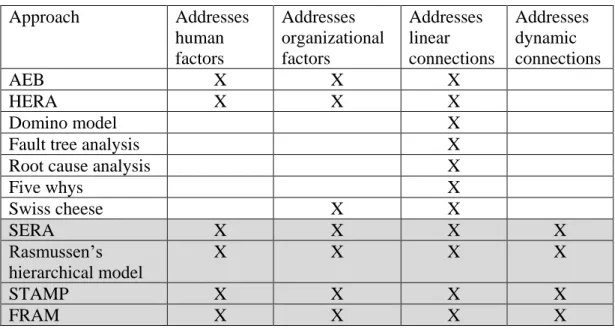
Traditional approaches, such as Root Cause Analysis (RCA) [34], Domino model [35], Fault Tree Analysis [36] and Five Whys method [37], model the accident as a consequence of the sequential, linear, time ordered events, which implies that once the root cause in the sequence is removed, the accident recurrence is stopped. Root Cause Analysis consists of four steps, namely, (i) gathering the data, (ii) representing events as sequence diagrams, (iii) analysis and
23 identification of root causes, and (iv) generation of counter measures. The Domino model is modelling events as a chain reaction in the domino failing effect, where each contributing factor is a consequence of the previous one in the chain, ending with the root cause. Fault Tree Analysis is a top down approach that models events as a logical tree, searching for the minimal cut set of the basic events that contributed to the top event. Five Whys is a top down method that builds causation chain by imposing a question “why” on the top event and on each answer provided in the chain. Since these traditional approaches are able to capture only linear relations between socio-technical entities, they cannot be applied on complex systems with dynamic behavior. [32] Also, these approaches are not distinguishing types of entities in STS and do not deliver any classification of failures for socio-technical entities.
AEB (Accident Evolution and Barrier Function) [38] is another example of a sequential approach that captures faulty linear interactions between human, organizational and technical entities and represents them as barriers in a flow diagram. It is important to highlight that AEB models only error event and not correct ones. AEB provides classification of barriers but lacks the classification that can be directly associated to human and organizational entities. HERA (Human Error in Air Traffic Management) [39], on the other hand, focuses on human error as a primary contributor to the accident. HERA addresses linear relations between entities and strives to identify all human error types, conditions of the task, environment and organizational factors. It provides an exhaustive classification of human and some of organizational errors types. However, the provided classification is highly related to avionics domain and it requires a study on applicability on other domains.
Systemic approaches are based on a system theory and see accident occurrence as a consequence of complex relationships and dependencies between all system components (human, technical, organization, environment, social) that can contribute to the failure.
One of the systemic concepts that considered all aspects of STS has been developed in Sweden and was named MTO (Man, Technology and Organization) [40]. The concept is similar to Human Factors (HF) concept developed in the USA and it suggested the holistic system view on system safety. MTO suggests that during safety risk assessment Man, Technology and Organization should not be analyzed separately, but instead they should be seen as one whole and analyzed together.
Several MTO-oriented risk assessment techniques emerged until today. One such approach is Reason’s Swiss cheese model [41] which considered that an accident is produced as a combination of triggered latent conditions and active failures committed by individuals or teams. Active failures and latent conditions are seen as holes on slices of the Swiss cheese, where slices of the cheese represent safety barriers and guards. Once the holes (failures) are lined up, failures will pass all barriers on each level and cause an accident. An approach based on the Reason’s Swiss cheese model is the Human Factors Analysis and Classification System (HFACS) [42] that provides taxonomy of human failures and preconditions on the supervision and organizational levels. HFACS represents a framework for systematical examination of the accidents and their causes. According to Reason, accidents are caused not only by human error but also by propagated latent failures in the upper layers in the
24 organizational hierarchy. HFACS describes four levels of failure: 1) Unsafe Acts, 2) Preconditions for unsafe acts, 3) Unsafe supervision, and 4) Organizational influences. However, HFACS models linear relation between human and organizational entities and provides fine classification of failures for both human and organizational failures.
Rasmussen’s socio-technical framework [43] adopts a concept of a system safety as a control structure problem based on the control loops through the organizational, management and operational structures. This framework has two parts: a hierarchical model, that describes the structure of the system, and a dynamic model. Hierarchical model (see Figure 5) represents a static view on the system which contains many control loops. Control flows from top layers (management) to bottom layers (executive layers), while at the same time the feedback flows in the opposite direction from bottom layers towards the upper layers. The dynamic model defines the boundaries of safe operations: economic boundary, unacceptable workload, and safety regulations boundary. Workload pressure and financial cost are strengthening the operational space towards safety regulations boundaries, which causes that over a time period, people cross the safety regulations boundary. System can still operate without accident until it does not reach functionally unacceptable behavior. Rasmussen’s socio-technical framework is able to address dynamic and complex relations between all entities in STS, but lacks an appropriate classification of failures of socio-technical entities.
Figure 5 – Rasmussen's hierarchical model of socio-technical system [32]
Similarly to the Rasmussen’s approach, STAMP (System-Theoretic Accident Model and Processes) [44] uses control loops to discover violated constraints on each control level. STAMP approach models accident causes not just as independent component failures, but also as external influences and dysfunctional interconnections between the internal components. “Safety can be viewed as a control problem, and safety is managed by a control structure embedded in adaptive socio-technical system.” [44] The first step in accident analysis using STAMP is the development of a hierarchical control structure. The hierarchical control structure is then analyzed to determine the constraints and causes of flawed control at each level. STAMP threats humans as any other entity in the system and applies the unified approach to all identified functions. The same approach can be used also for risk assessment
25 during the system development phase. STAMP successfully addresses complex dynamic relations between entities in STS by focusing on interactions among components. However, the provided classification of failures is capturing failures at control loop level (Figure 6) and can be rather associated to organizational level than to human behavior.
Figure 6 - STAMP Classification of failures in control loops [44]
Several techniques based on the formal methods are available as well, but they are focused on the design and verification of systems, and an extension towards socio-technical aspects is needed.
Systemic cognitive systems engineering approaches such as the Functional Resonance Accident Model (FRAM) [45] model systems with human and technology interaction in the context of the workplace and its environment. FRAM addresses complex and dynamic relations in STS using the concept of functional variability. FRAM describes how the coupling and dependencies between system functions can contribute to an accident occurrence through unhandled propagation of human, technological and organizational performance variability. The FRAM risk assessment starts with an identification and characterization of the essential system functions. The characterization can be made based on the six connectors of the hexagonal functional representation (Figure 7): Input, Output, Resources (what is needed by the function to process the input), Controls (serves to supervise or restrict the function), Preconditions (system condition), Time (time constraints such as start and finish time or duration). System functions are interconnected using input and output ports, which in the end form a structure which allows tracking of the failure propagation through functions. However, FRAM models might need more than one connection between functions to express one event which is seriously reducing readability and understanding. The next steps are characterization of the potential variability, definition of functional resonance based of dependencies among functions, and identification of barriers for variability.
26 Figure 7 - FRAM Hexagonal function representation [45]
Various ways in which an output can differ from the expected values (resonance) can be expressed using failure modes. Also, FRAM considers the common performance conditions (Figure 8) that lead to performance variability of human, technical and organizational functions and defines the likelihood for the variability. However, the common performance conditions might affect functions of all MTO categories and cannot be used to classify the failures of any of the MTO categories.
Figure 8 - FRAM - Match between MTO categories and common performance conditions [45] 2.6.2. Systematic Error and Risk Analysis
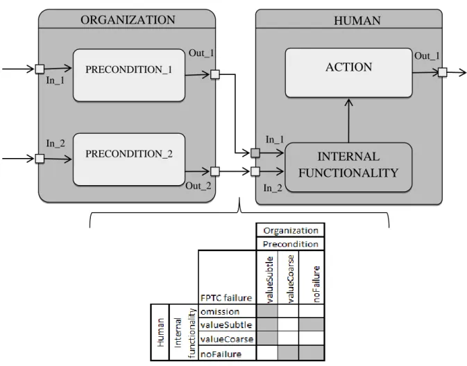
Systematic Error and Risk Analysis (SERA) [46] allows systematic investigation of accidents with a focus on human factors and related preconditions to accidents. It combines Reason’s latent failures model with multi-layered Perceptual Control Loops (PCL) (see Figure 9) and delivers a process for identifying active failures and preconditions that lead to these failures. Active failures are the unsafe acts that can be directly connected to accident. However, SERA does not focus on human error and blame of individuals, but rather on the organizational influences that support human errors. Moreover, SERA addressed the interrelatedness of organizational faults and human faults in terms of direct relation between them (see Appendix A). SERA also considered the impact of human internal preconditions for faults such as physical and psychical states. Also, SERA is based on a mature approach called HFACS
27 whose application was studied by many researchers from many different domains ([48], [49], [50], [51]) including the petroleum domain [52]. Initially, SERA was designed to help accident investigators in performing the HFACS analysis, but it has been developed as a standalone analysis approach with its own, even broaden classification of failures.
Figure 9 - Perceptual control loop for a human interacting with the world [46]
PCL at human level (see Figure 9) describes the human decision processes as a reaction to feedback received as a perception of real world and human model of the world. SERA establishes a PCL on each of the four levels of the Reason’s latent failures model interpreted as:
Active failures – represented as twelve points of a breakdown in human information processing system;
Preconditions for unsafe acts – preconditions that are directly connected with active failures, defined as condition of the personnel, condition of the task and working conditions;
Command, Control and Supervision (C2S) – related to the management activities for forming the goals and providing feedback;
Organizational influences – represented as organizational factors that create a space for flaws on lower levels in the organizational hierarchy.
Using PCL loops at each defined level, SERA is able to capture dynamic relations between entities in STS. It also provides an exhaustive classification of human and organizational failures at each level and provides a detailed mapping of relations between those failures. SERA also considered the contribution of the state of the human to the accident occurrence. A classification of human and organizational failures is represented as active failures and preconditions that lead to these failures.
Twelve categories of active failures that humans can produce are:
1. Intent failure - The intention failure is a result of the action that was performed to achieve the goal that is either not consistent with the rules and regulations (violation) or the goal that is consistent but not appropriate to the human that performs a task;
28 2. Attention failure - Attention failure represents a failure in human internal functionality that manifests as a failure to attend all the relevant information that was present;
3. Sensory failure - Sensory failure occurs in the case in which a human does not have the physical capabilities such as hearing, eyesight and other sensory capabilities to perform the task;
4. Knowledge (perception) failure - This failure occurs in case when a human does not have knowledge or skills to properly interpret the situation;
5. Perception failure - Perception failure occurs when all relevant information was attended, but the content was ambiguous. It can occur due to the human processing nature that can filter the available information;
6. Communication/Information failure - Communication failure is the failure in the communication channel between humans or between a human and a machine. Due to a communication channel failure a human could not receive the relevant information, or the wrong or incorrect information could be received;
7. Time management failure - Time management failure is “a failure to use appropriate and effective time management strategies, including: incorrect or inappropriate prioritization of attention, failure to delegate, postpone, shed tasks, failure to simplify the task, failure to take control of the timeline of the activity, or a failure to pre-plan or bring tasks forward. “ [46] ;
8. Knowledge (Decision) failure - occurs when a human does not have a knowledge or skills to make an appropriate decision required to successfully complete the task; 9. Ability to respond failure - A failure in the ability to respond relates to the lack of
human physical abilities (e.g. strength, vocal effort) to provide a response required to achieve the task goal;
10. Action selection failure - This is “a failure in the decision process due to the shortcomings in action selection, rather than a misunderstanding or misperception of the situation. This includes an inappropriate ‘no action’.” [46] ;
11. Slips, Lapses and Mode errors - This failure occurs when a response is not performed according to the intention. Slips usually occur when an action slightly differs from the routine. Mode errors are related to actions that are inappropriate for current working mode, but correct for another mode;
12. Feedback failure - Feedback failure occurs when a human does not receive any feedback information that could be used for correcting actions. This is a failure in error correction since there is nothing that will acknowledge human that the goal is achieved. It includes a failure at the individual (monitoring, checking) and team (crosschecking, supervision, backing up) level.
The preconditions for unsafe acts describe the condition of:
Personnel – This condition is further broken down and represented as seven states of the individual, working both individually and as a team or a group:
1. Physiological - physiological state of the individual such as drowsiness, medical illness, intoxication, etc. ;
29 2. Psychological - psychological states, attitudes, traits, and processing biases
that can affect perception, action selection, or forming an action; 3. Social – factors that influence the interaction among groups and teams;
4. Physical capability – factors related to the physical abilities to sense and perform an action;
5. Personnel readiness – the state of the individual in the sense of a physiological, psychological, physical and mental readiness to perform a task; 6. Training and selection – refers to the skills and knowledge required to do the
job;
7. Qualification and authorization – refers to the legal pre-requisites to perform a task such as proper qualification and authorization.
Task – This condition is further decomposed on two factors:
1. Time pressure - Time pressure occurs when the pace of the task is extreme or when humans, paced by the task, have little scope to actively manage the task timeline;
2. Objectives - Objectives failure refers to unclear, inappropriate, inconsistent and risky task objectives.
Working conditions – These conditions are further decomposed on following factors: 1. Equipment – This factor refers to a condition of tools used to carry out the
task;
2. Workspace – This factor describes the physical arrangement and layout of the workspace;
3. Environment - This factor describes conditions of the environment in which the activity is performed.
C2S failures are defined in the following terms:
1. Forming intent – Refers to the unclear forming of the objectives of the task, and the assignment of responsibility by managers and supervisors;
2. Communicating intent – The intent was well formed, but the failure occurs due to the unclear communication of intent;
3. Monitoring and Supervision – a failure in the monitoring or supervision activities manifested as a missing, delayed or inadequate error-correcting activity that ensures a successful task or mission completion.
Organizational influences cover the following six factors:
1. Mission - Mission factor refers to the cases when a mission is not clearly defined, approved, or inconsistent with the available resources;
2. Provision of resources - This refers to the management and provision of the resources that include humans, equipment, money and funds, needed to successfully complete the task;
3. Rules and regulations – refers to the set of rules and regulations that set legal constraints on processes in organization. This factor questions whether procedures, mission, operations and goals are set according to the rules and regulations and
![Figure 7 - FRAM Hexagonal function representation [45]](https://thumb-eu.123doks.com/thumbv2/5dokorg/4874838.133143/26.892.317.575.112.292/figure-fram-hexagonal-function-representation.webp)

![Figure 14 - Activity diagram related to Concerto-FLA [5]](https://thumb-eu.123doks.com/thumbv2/5dokorg/4874838.133143/44.892.171.720.319.563/figure-activity-diagram-related-concerto-fla.webp)