Postprint
This is the accepted version of a chapter published in Progress in Gas Turbine Performance.
Citation for the original published chapter:
Kyprianidis, K., Rolt, A., Sethi, V. (2013)
On Intercooled Turbofan Engines.
In: Ernesto Benini (ed.), Progress in Gas Turbine Performance (pp. 3-24). Rijeka, Croatia: InTech
N.B. When citing this work, cite the original published chapter.
Permanent link to this version:
On Intercooled Turbofan Engines
Konstantinos G. Kyprianidis, Andrew M. Rolt and
Vishal Sethi
Additional information is available at the end of the chapter http://dx.doi.org/10.5772/54402
On Intercooled Turbofan Engines
Konstantinos G. Kyprianidis, Andrew M. Rolt and Vishal Sethi
Additional information is available at the end of the chapter
10.5772/54402
1. Introduction
Public awareness and political concern over the environmental impact of the growth in civil aviation over the past 30 years have intensified industry efforts to address CO2emissions [5]. CO2 emissions are directly proportional to aircraft fuel burn and one way to minimise the latter is by having engines with reduced Specific Fuel Consumption (SFC) and installations that minimise nacelle drag and weight. Significant factors affecting SFC are propulsive efficiency and thermal efficiency. Propulsive efficiency has been improved by designing turbofan engines with bigger fans to give lower specific thrust (net thrust divided by fan inlet mass flow) until increased engine weight and nacelle drag have started to outweigh the benefits. Thermal efficiency has been improved mainly by increasing the Overall Pressure Ratio (OPR) and Turbine Entry Temperature (TET) to the extent possible with new materials and design technologies.
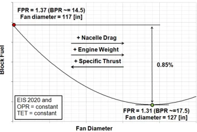
Mission fuel burn benefits from reducing specific thrust are illustrated in Fig. 1 (for a year 2020 entry into service, but otherwise conventional, direct drive fan engine for long range applications). The engine Take-Off (TO) thrust at Sea Level Static International Standard Atmosphere (SLS ISA) conditions is 293.6kN (66000lbf) and all Fan Pressure Ratio (FPR) and ByPass Ratio (BPR) values quoted are at mid-cruise conditions. The figure shows that only a modest reduction in block fuel is obtained by increasing the already large fan diameter. Reduced powerplant weight and/or nacelle drag would be needed before lower specific thrust would be justified, and one way of doing this would be to discard the nacelle and fit an open rotor in place of the fan.
An alternative design approach to improving SFC is to consider an increased OPR intercooled core performance cycle. The thermal efficiency benefits from intercooling have been well documented in the literature - see for example [2, 3, 7, 9, 11–13, 15]. Very little information is available however, with respect to design space exploration and optimisation for minimum block fuel at aircraft system level.
©2012 Kyprianidis et al., licensee InTech. This is an open access chapter distributed under the terms of the Creative Commons Attribution License (http://creativecommons.org/licenses/by/3.0), which permits unrestricted use, distribution, and reproduction in any medium, provided the original work is properly cited.© 2013 Kyprianidis et al.; licensee InTech. This is an open access article distributed under the terms of the
Creative Commons Attribution License (http://creativecommons.org/licenses/by/3.0), which permits unrestricted use, distribution, and reproduction in any medium, provided the original work is properly cited.
Figure 1. Block fuel benefits from reducing specific thrust for a year 2020 entry into service conventional turbofan engine for
long range applications.
Previously, a comparative study was presented focusing on a conventional core and an intercooled core turbofan engine for long range applications [5, 7]. Both configurations had the same fan diameter and were designed to meet the same thrust requirements. They were Ultra-High Bypass Ratio (UHBR) designs based on a three-shaft layout with a direct drive front fan. The intercooled core configuration (illustrated in Fig. 2) featured an intercooler mounted inboard of the bypass duct. The installation standard included a flow splitter and an auxiliary variable geometry nozzle. The two concepts were evaluated based on their potential to reduce CO2 emissions (and hence block fuel) through both thermal and propulsive efficiency improvements, for engine designs to enter service between 2020 and 2025. Although fuel optimal designs were proposed, only limited attention was given to the effect of design constraints, material technology and customer requirements on optimal concept selection.
A study is presented here that focuses on the re-optimization of those same powerplants by allowing the specific thrust (and hence the propulsive efficiency) to vary. Rather than setting fixed thrust requirements, a rubberised-wing aircraft model was fully utilised instead. The engine/aircraft combination was optimized to meet a particular set of customer requirements i.e. payload-range, take-off distance, time to height and time between overhaul. It was envisaged that different conclusions would be drawn when comparing the two powerplants at their optimal specific thrust and absolute thrust levels. It is shown through this study that performing a comparison at each concept’s optimal specific thrust level gives a different picture on intercooling. Differences in the optimal specific thrust levels between the two configurations are discussed. The design space around the proposed fuel-optimal designs was explored in detail and significant conclusions are drawn.
Figure 2. Artistic impression of the intercooled core turbofan engine [10].
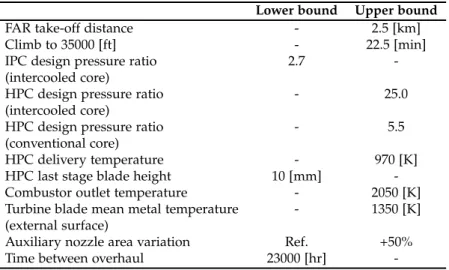
Lower bound Upper bound
FAR take-off distance - 2.5 [km]
Climb to 35000 [ft] - 22.5 [min]
IPC design pressure ratio 2.7
-(intercooled core)
HPC design pressure ratio - 25.0
(intercooled core)
HPC design pressure ratio - 5.5
(conventional core)
HPC delivery temperature - 970 [K]
HPC last stage blade height 10 [mm]
-Combustor outlet temperature - 2050 [K]
Turbine blade mean metal temperature - 1350 [K] (external surface)
Auxiliary nozzle area variation Ref. +50%
Time between overhaul 23000 [hr]
-Table 1. Design space constraints.
2. Methodology
To effectively explore the design space a tool is required that can consider the main disciplines typically encountered in conceptual design. The prediction of engine performance, aircraft design and performance, direct operating costs and emissions for the concepts analysed in this study was made using the code described in [6]. Another code described in [7], was also used for carrying out the mechanical and aerodynamic design in order to derive engine component weights and dimensions. The two tools have been integrated together within an optimizer environment as illustrated in Fig. 3 with a large amount of information being made available to the user during the design iteration. The integration allows for multi-objective optimization, design studies, parametric studies, and sensitivity analysis. In order to speed up the execution of individual engine designs, the conceptual design tool minimizes internal iterations in the calculation sequence through the use of an explicit algorithm, as described in detail by Kyprianidis [4].
For every engine design there are numerous practical limitations that need to be considered. A comprehensive discussion on design constraints for low specific thrust turbofans featuring conventional and heat exchanged cores can be found in [5]. The design space constraints set for this study are given in Table 1 and are considered applicable to a year 2020 entry into service turbofan engine. The effect on optimal concept selection of design constraints, material technology and customer requirements is discussed in the following sections.
3. Optimising a turbofan engine
3.1. Fuel-optimal designs
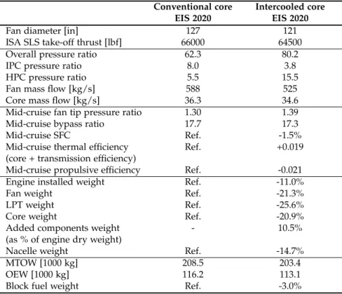
Optimizing a turbofan engine design for minimum block fuel essentially has to consider the trade-off between better thermal and propulsive efficiency and reduced engine weight and nacelle drag. The cycle optimization results for the two powerplants are given in Table 2.
Conventional core Intercooled core
EIS 2020 EIS 2020
Fan diameter [in] 127 121
ISA SLS take-off thrust [lbf] 66000 64500
Overall pressure ratio 62.3 80.2
IPC pressure ratio 8.0 3.8
HPC pressure ratio 5.5 15.5
Fan mass flow [kg/s] 588 525
Core mass flow [kg/s] 36.3 34.6
Mid-cruise fan tip pressure ratio 1.30 1.39
Mid-cruise bypass ratio 17.7 17.3
Mid-cruise SFC Ref. -1.5%
Mid-cruise thermal efficiency Ref. +0.019
(core + transmission efficiency)
Mid-cruise propulsive efficiency Ref. -0.021
Engine installed weight Ref. -11.0%
Fan weight Ref. -21.3%
LPT weight Ref. -25.6%
Core weight Ref. -20.9%
Added components weight - 10.5%
(as % of engine dry weight)
Nacelle weight Ref. -14.7%
MTOW [1000 kg] 208.5 203.4
OEW [1000 kg] 116.2 113.1
Block fuel weight Ref. -3.0%
∗Performance parameters at top of climb conditions unless stated otherwise
Table 2.Comparison of the fuel optimal intercooled and conventional core turbofan engine designs.
Significant block fuel benefits are projected for the intercooled core engine, but they are smaller than those predicted in previous efforts [7]. This is mainly attributed to a minimum blade height requirement setting a practical lower limit on the intercooled core size for a given OPR. Increasing the fan diameter at a fixed tip speed inevitably reduces rotational speed, increases torque and hence increases the Low Pressure (LP) shaft diameter; this further aggravates the problem since the High Pressure Compressor (HPC) hub to tip ratio needs to increase. As a result, the optimal specific thrust for the intercooled core is higher compared to the conventional core turbofan engine. Although the high OPR intercooled core benefits from a higher core and transmission efficiency, and hence a better thermal efficiency, the conventional core benefits from a higher propulsive efficiency. The design space around the proposed fuel optimal designs was explored and in the next sections important observations are presented.
3.2. Approximating the design space
In order to graphically illustrate the design space, a large number of simulations had to be carried out; these simulations were focused around the fuel-optimal designs presented in Section 3.1. Polynomial response surface models were derived that interpolate between
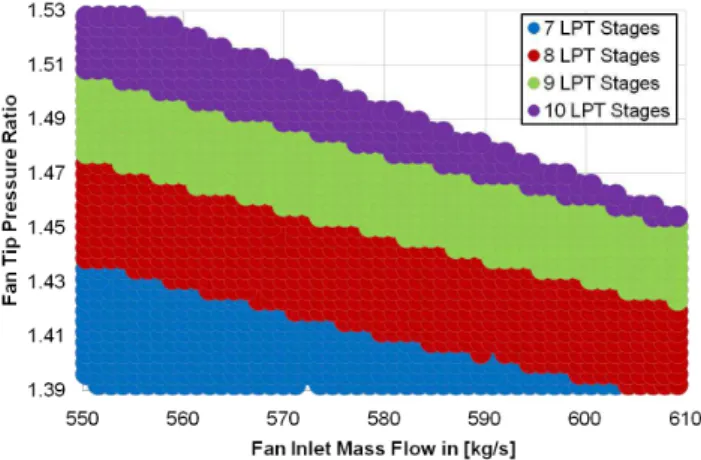
Figure 4. Variation of low pressure turbine stage count with fan inlet mass flow and fan tip pressure ratio for a fixed size
conventional core.
a given number of known designs. Typical design space discontinuities encountered as a result of turbomachinery stage count changes are inevitably distorted in polynomial approximations. For this reason, an error analysis was carried out to determine the discrepancy levels between the surrogate models and the actual design spaces; the approximation errors for engine weight and aircraft block fuel were found to be less than 1% and 0.2%, respectively.
3.3. Fan and core sizing
Propulsive efficiency benefits from reducing specific thrust by increasing fan diameter can very well be negated by the resulting combination of: i) increased engine and nacelle weight, ii) increased nacelle (and interference) drag, and iii) reduced transmission efficiency. This section discusses various aspects of fan and core sizing for the conventional core and intercooled core configurations.
When sizing the engine fan, assuming a fixed size core (i.e., fixed core inlet mass flow), large design space discontinuities are encountered due to Low Pressure Turbine (LPT) stage count changes, as illustrated in Fig.4.
As discussed earlier, the use of smooth surrogate models for approximating discontinuous spaces inevitably results in approximation errors, and it is worth noting that the addition of an extra LPT stage results in approximately 150kg of additional weight. Nevertheless, with the fan and nacelle weight (including the thrust reverser) each being roughly double the LPT weight and directly proportional to the fan diameter, the weight trends illustrated in Fig. 5 can be considered reasonable.
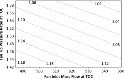
The improvement in mid-cruise uninstalled SFC from reducing specific thrust is illustrated in Fig. 6. If installation effects are ignored, then selecting a higher fan diameter (and hence a higher bypass ratio at a fixed size core) will result in better SFC. Nevertheless, the increased nacelle drag and engine weight move the optimal level of specific thrust for minimum block fuel to smaller fan diameters, as illustrated in Fig. 7.
Figure 5. Variation of engine weight with fan inlet mass flow and fan tip pressure ratio for a fixed size conventional core.
Figure 6. Variation of engine specific fuel consumption with fan inlet mass flow and fan tip pressure ratio for a fixed size
conventional core.
Looking at the trends illustrated in Fig. 7 in isolation, and then comparing with the optimal design proposed in Section 3.1, one would be inclined to draw the conclusion that the fuel-optimal fan diameter should be even smaller. However, as one moves towards the upper left corner of Fig. 7 the engine take-off and Top Of Climb (TOC) thrusts reduce (because the core size is fixed and the fan is getting smaller. In order to satisfy - at constant specific thrust - the time to height and FAR (Federal Aviation Regulations) take-off distance constraints set in this study it is necessary to scale-up the engine i.e., increase fan and core size simultaneously which leads to: i) higher engine and nacelle weight, ii) higher nacelle drag, and iii) non-optimum engine/aircraft matching i.e. mid-cruise conditions are away from the bottom of the SFC loop (particularly if other cycle parameters are not re-optimized).
Figure 7. Variation of aircraft block fuel with fan inlet mass flow and fan tip pressure ratio for a fixed size conventional core.
Most of the conclusions drawn in this section are applicable to both the conventional core and the intercooled core configurations. Nevertheless, the intercooled core is constrained by a practical minimum blade height requirement for the last HPC stage (assuming an all-axial bladed HPC). At a fixed core OPR and intercooler effectiveness, this constraint sets a minimum limit for the core mass flow and as a consequence a minimum limit is also set on specific thrust at a fixed engine thrust. This makes the intercooled core more favourable for very high thrust engines, as they will not be subject to this constraint.
Figure 8. Variation of HPC last stage blade height with fan inlet mass flow and fan tip pressure ratio for a fixed size intercooled
Figure 9. Variation of HPC last stage blade height with fan inlet mass flow and fan tip pressure ratio for a fixed size conventional
core.
Bigger direct drive fans rotating at low speeds result in high torque requirements which increase the LP shaft outer diameter. The HPC inner diameter has to be pushed out and therefore slowed down, so for a given flow area and blade speed, the resulting blade height tends to reduce, as illustrated in Fig. 8 - the problem is less marked for a conventional core as illustrated in Fig. 9. For a given blade height requirement the core mass flow needs to be increased and it can therefore be concluded that an intercooled core would favour a geared fan arrangement, over a direct drive one, since it could alleviate some of the restrictions set on the cycle. An aft fan arrangement as the one presented in [1] could further relieve this issue by not passing the LP shaft through the core, though aft fan arrangements set other design challenges.
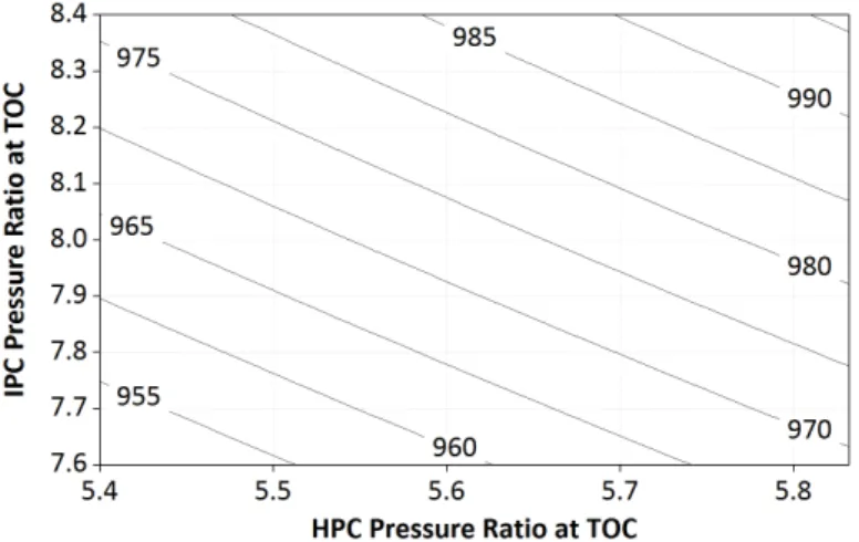
3.4. IPC/HPC work split
Increasing engine OPR improves thermal efficiency and hence SFC, as illustrated in Fig. 10. The optimal OPR level for the conventional core is constrained by the maximum allowable HPC delivery temperature set, as illustrated in Fig. 11. For the intercooled cycle, this limitation is alleviated but only to be replaced by a practical minimum blade height requirement which consequently sets a minimum allowable core size constraint. The optimal OPR level for the intercooled core at a fixed specific thrust is therefore a trade-off between a better core efficiency and a smaller core size.
If one assumed constant component polytropic efficiencies then SFC benefits would arise for the conventional core from shifting pressure ratio to the more efficient High Pressure (HP) spool.
However, as the HPC pressure ratio rises beyond an upper limit set, the core configuration would inevitably need to be changed to a two-stage High Pressure Turbine (HPT). This would introduce higher cooling flow requirements (and hence losses) and could also make the core
Figure 10. Variation of mid-cruise specific fuel consumption with IPC and HPC pressure ratio for a fixed size conventional core.
Figure 11. Variation of take-off HPC exit temperature with IPC and HPC pressure ratio for a fixed size conventional core.
heavier and longer, negating the originally projected benefits. Efficient intercooling requires that the Intermediate Pressure Compressor (IPC) has significantly less pressure ratio than the HPC [14]. For that reason, a two-stage HPT has been assumed for the intercooled core while a minimum IPC design pressure ratio was set to avoid potential icing problems during decent.
3.5. Engine ratings
Sizing and rating an engine is a highly complex process that has to consider aircraft performance requirements, fuel consumption, and engine lifing. Turbine blade lifing requirements and cooling technology set a maximum allowable blade metal temperature
Figure 12. Variation of engine weight with combustor outlet temperature at take-off and top of climb conditions for a fixed
size conventional core.
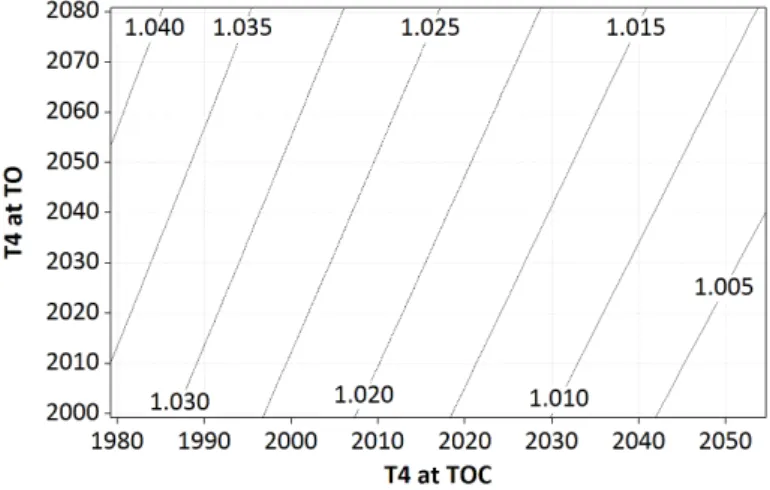
constraint; cooling flows therefore need to increase with increasing combustor outlet temperature (T4) levels. The maximum T4level may also be constrained by combustor design considerations. For example increasing combustor liner cooling requirements essentially reduces the amount of air available for mixing in the combustion zone and hence the flame temperatures and NOx emissions tend to increase. Detail design studies are required for establishing the optimal trade-off between cycle efficiency and acceptable NOx levels. For these reasons an upper limit was set for T4that was considered to be a reasonable trade-off for year 2020 entry into service turbofan engines. The same limit was used for both the conventional core and the intercooled core.
Although the intercooled core benefits from lower combustor inlet temperatures, the air to fuel ratio is lower for a given T4. Furthermore, high pressure levels in the intercooled cycle will affect the influence of luminosity on gas emissivity, and hence the temperature difference across the liner [8].
For a given OPR there is an optimal mid-cruise T4for best SFC. Nevertheless, running the cycle hotter at top of climb (than the optimal for mid-cruise SFC) tends to reduce engine weight, as illustrated in Fig. 12. These benefits come mainly from the reduction in LPT weight since a higher T4results in a more efficient core expansion and hence a higher pressure and lower corrected mass flow at the LPT inlet. A further reduction in weight is possible through the reducing core size (mainly in the case of the conventional core) since core output is increasing with T4. On the other hand, running the cycle hotter at hot day take-off can lead to an increase in engine weight at a fixed core size. An increase in T4at top of climb generally requires an increase in T4at take-off in order to maintain a constant FAR take-off field length. T4 at top of climb is therefore constrained by a hot-day take-off T4limitation. Furthermore, with modern large engines on long range aircraft typically being heavily derated at take-off conditions milder than hot-day and/or with less than a full fuel load, top of climb T4 will want to be lower than hot-day take-off T4 so as not to compromise engine life [12]. An optimal block fuel trade-off therefore arises as illustrated in Fig. 13.
Figure 13. Variation of aircraft block fuel with combustor outlet temperature at take-off and top of climb conditions for a fixed
size conventional core.
3.6. Intercooler effectiveness
In this study the aerodynamic design for most engine components has been carried out at top of climb conditions. However, the intercooler component has been sized at end of runway hot day take-off conditions (kink point) were the highest heat transfer levelswhere the highest heat transfer levels are encountered. At cruise conditions the variable geometry dual-nozzle system is utilised to reduce the intercooler mass flow ratio (intercooler cooling mass flow divided by core mass flow) and hence reduce intercooler cold side pressure losses. This practice results in better SFC and hence lower block fuel.
Engine design variations focused around the fuel optimal design are presented in Fig. 14 in a similar manner to figures presented in earlier sections. The figure illustrates the effect of intercooler effectiveness on weight. As can be observed, intercooler effectiveness at top of climb conditions has only a second order effect on intercooler weight while intercooler effectiveness at take-off conditions has a more significant effect. As intercooler weight increases, so does block fuel. Further to increasing intercooler weight, increasing intercooler cooling air flow and effectiveness at take-off conditions increases thrust at a given combustor outlet temperature. This thrust improvement however is soon negated by increasing intercooler cold side pressure losses, as discussed in detail in [7].
It can be observed in Fig. 15 that there is a limit to the block fuel benefit that may be achieved by optimising the intercooler effectiveness level at different flight conditions. This limitation is set by: i) the maximum allowable nozzle area variation (dot-dashed white iso-lines), and from ii) the reducing overall pressure ratio level during cruise conditions (white continuous iso-lines). Although at first glance it seems to be implied through this figure that a low intercooler effectiveness is beneficial for block fuel, it should be noted that a minimum level of intercooler effectiveness has to be maintained at take-off (and hence at cruise due to the aforementioned nozzle area variation limitation). This is due to the need for satisfying a maximum FAR take-off field length requirement at a given maximum combustor outlet temperature. An optimal trade-off therefore exists between intercooler effectiveness,
Figure 14. Variation of intercooler weight with intercooler effectiveness at top of climb and take-off conditions.
specific thrust, core size, and overall pressure ratio. It should be stressed that the optimum design intercooler effectiveness level also clearly depends on the heat exchanger technology available.
These significant performance benefits - being the result of controlling the amount of cooling flow going through the intercooler, and hence the effectiveness and pressure loss levels at different operating points - may be achieved not only by utilising a variable geometry dual-nozzle system but alternatively through a variable area mixer, which returns spent intercooler air to the bypass duct. Optimal variable geometry settings can be identified for different operating points and the projected benefits are up to 2% increase in net thrust (FN) at take-off and 2% reduction in SFC at cruise.
4. Sensitivity analysis of optimal designs
The work presented in this section aims to deliver averaged exchange rates which can be used to investigate the effect of technology parameter deviations on block fuel. Information on how these perturbations were introduced in the design algorithm is given in Appendix A. The sensitivity parameters compiled allow for system level quantification of the importance of research on specific component technologies i.e. they can be used to assess the significance of progress in specific component technologies for each engine configuration. Inversely, these exchange factors also help quantify the impact of technology shortfalls. The exchange rates presented in Fig. 16 and Fig. 17 should be perceived as fractional percentage variations from the technology target values that were assumed when deriving the fuel optimal designs presented in Section 3.1.
For the conventional core configuration for long range applications the low pressure system component technology has the greatest influence on performance, as expected for a low specific thrust engine. Significant fuel burn benefits are expected by improving fan and LPT efficiency. Inversely, shortfalls in meeting projected technology targets for the low pressure system will have a major impact on overall engine/aircraft performance.
As fan tip pressure ratio reduces, pressure losses in the bypass duct tend to have an increasingly dominant effect on transmission efficiency and, therefore, on the impact of propulsive efficiency improvements on SFC. By combining Fig. 1 and Fig. 16 it can be observed that a 10% increase in bypass duct pressure losses would halve the projected block fuel benefits from a 10 [in] increase in fan diameter and the consequent reduction in specific thrust.
Failure to deliver the expected efficiency levels for the compressor components would increase combustor inlet temperatures resulting in higher NOx levels and reduced component life. Combustor designs are highly sensitive to inlet conditions and it is likely that a significant shortfall in compressor efficiency would require a re-design of the combustor as well as the compressors.
The influence of the low pressure system component technology on performance is less marked for the intercooled core configuration compared to the conventional core. The difference in the exchange rates is directly proportional to the difference in specific thrust between the two optimal designs.
Figure 16. Sensitivity analysis around the fuel optimal design for the conventional core configuration.
Figure 17. Sensitivity analysis around the fuel optimal design for the intercooled core configuration.
The efficiencies of the IPC and Intermediate Pressure Turbine (IPT) in the intercooled core for long range applications have a significantly smaller influence on block fuel, compared to the conventional core configuration, which reflects the significantly lower pressure ratio on the Intermediate Pressure (IP) spool. On the other hand, the efficiencies of the HPC and HPT have a similar influence on block fuel, compared to the conventional core configuration, despite the significantly higher pressure ratio placed on the HP spool. This can be explained by the fact that by reducing the HPC inlet temperature, intercooling significantly reduces HP compression work at a pressure ratio, and also increases the specific power of the core. As can be observed, intercooler pressure losses have a significant effect on block fuel. Losses in the intercooler hot stream are more significant than losses in the cold stream at cruise and
climb, while losses in the cold stream become increasingly important as the intercooler mass flow ratio (W132Q25) increases at take-off. Failure to achieve the intercooler pressure loss targets set could significantly reduce the projected block fuel benefits for the intercooled core configuration.
5. Conclusions
In this study, the combined potential of novel low pressure spool and core technologies was assessed with respect to reducing engine CO2emissions. A back-to-back comparison of an intercooled core engine with a conventional core engine was performed and fuel optimal designs for year 2020 entry into service were proposed.
The results from the optimization process show that the optimal specific thrust for the intercooled core is somewhat higher compared to the conventional core turbofan engine. This is mainly attributed to the HPC last stage blade height requirement limiting minimum core size in the intercooled engine and negating one of the benefits of increasing fan diameter. This conclusion may appear specific to the thrust scale of the study engine and it might not apply to more powerful engines, but it is considered likely to be generally applicable because all intercooled engines have relatively small core size and so will be more susceptible to the loss of core component efficiency associated with making the core smaller still.
The optimized high OPR intercooled core benefits from higher thermal efficiency, but the optimized conventional core still benefits from higher propulsive efficiency. As a remedy to this, it is proposed to remove the LP shaft diameter constraint to enable the intercooled engine to have a faster more efficient lower hub to tip ratio core. This may be achieved by having a geared fan and a high-speed LP turbine with a smaller diameter shaft, or an aft fan arrangement (with a geared or counter-rotating turbine) or by having a reverse-flow core. Any of these arrangements might reduce the optimal specific thrust level significantly but would make 2020 a very ambitious target for entry into service.
It can be concluded that significant benefits in terms of block fuel are possible from an intercooled core, with year 2020 entry into service level of technology, compared to a conventional core turbofan engine for long range applications. However, the benefits are highly dependent on achieving technology targets such as low weight and pressure losses for the intercooler. The commercial competitiveness of an intercooled core turbofan design will largely depend on how the aviation market evolves in the years to come.
Acknowledgements
This study has been performed under the project NEWAC (European Commission Contract No. AIP5-CT-2006-030876). The authors gratefully acknowledge this funding as well as the project partners collaboration. In more detail, the work in this paper was performed under NEWAC WP1.3, “Techno-Economic and Environmental Risk Assessment” and Cranfield University, and Rolls-Royce plc specifically contributed to the work presented in the paper. The authors are grateful to J.A. Borradaile, S. Donnerhack (MTU Aero Engines), A. Lundbladh (GKN Aerospace), T. Grönstedt (Chalmers University), L. Xu (Siemens), B. Lehmayr (University of Stuttgart) and A. Alexiou (National Technical University of Athens) for the stimulating discussions on advanced concepts and aero engine design. Many thanks go to the reviewers of this work for their constructive suggestions to improve the overall quality and clarity of the article.
Nomenclature
BP ByPass duct
BPR ByPass Ratio
CO2 Carbon dioxide dP/Pin Fractional pressure loss EIS Entry Into Service
FN Net thrust
FAR Federal Aviation Regulations
FL Flight Level
FPR Fan Pressure Ratio
HP High Pressure
HPC High Pressure Compressor HPT High Pressure Turbine
IC InterCooler
ICAO International Civil Aviation Organisation IP Intermediate Pressure
IPC Intermediate Pressure Compressor IPT Intermediate Pressure Turbine ISA International Standard Atmosphere
LP Low Pressure
LPT Low Pressure Turbine Mid-Cr Mid-Cruise
MTOW Maximum Take-Off Weight NOx Nitrogen oxides
OEW Operating Empty Weight OPR Engine Overall Pressure Ratio P2 Fan inlet pressure
P23 Intermediate pressure compressor inlet pressure P25 Intermediate pressure compressor outlet pressure P3 High pressure compressor outlet pressure Pol. Eff. Polytropic Efficiency
PR Pressure Ratio
SFC Engine Specific Fuel Consumption SLS Sea Level Static
T4 Combustor outlet temperature
T41 High pressure turbine rotor inlet temperature TET Turbine Entry Temperature
TO Take-Off
TOC Top Of Climb
UHBR Ultra High Bypass Ratio
Appendix: Optimisation design variables
This appendix provides additional information on the choice of design variables for the optimisation process utilised in this article. Unless explicitly stated otherwise, design variables refer to top of climb engine operating conditions (ISA +10 [K], FL350, Mach=0.82) which is set as the reference (design) point for engine performance. The effect of introducing a single design variable perturbation on the values of other parameters at design point and off-design conditions is described by Fig. 18 and Fig. 19, respectively. Similarly, Fig. 20 describes the effect of such perturbations on the values of mechanical design parameters and objective functions.
Figure 18. Main design variables for the direct drive fan conventional and intercooled core engine configuration and their effect on the values of other parameters at top of climb.
Figure 19. Main design variables for the direct drive fan conventional and intercooled core engine configuration and their effect on the value s of other parameters at different off-design conditions.
Figure 20. Main design variables for the direct drive fan conventional and intercooled core engine configuration and their effect on the values of mechanical design parameters and objective functions.
Author details
Konstantinos G. Kyprianidis1, Andrew M. Rolt1and Vishal Sethi2 1 Rolls-Royce plc, UK
2 Cranfield University, UK
References
[1] Borradaile, J. [1988]. Towards the optimum ducted UHBR engine, Proceedings of AIAA/SAE/ASME/ASEE 24th Joint Propulsion Conference, AIAA-89-2954, Boston, Massachusetts, USA.
[2] Canière, H., Willcokx, A., Dick, E. & De Paepe, M. [2006]. Raising cycle efficiency by intercooling in air-cooled gas turbines, Applied Thermal Engineering 26(16): 1780–1787. [3] da Cunha Alves, M., de Franca Mendes Carneiro, H., Barbosa, J., Travieso, L., Pilidis,
P. & Ramsden, K. [2001]. An insight on intercooling and reheat gas turbine cycles, Proceedings of the Institution of Mechanical Engineers, Part A: Journal of Power and Energy 215(2): 163–171.
[4] Kyprianidis, K. [2010]. Multi-disciplinary Conceptual Design of Future Jet Engine Systems, PhD thesis, Cranfield University, Cranfield, Bedfordshire, United Kingdom.
[5] Kyprianidis, K. [2011]. Future Aero Engine Designs: An Evolving Vision, in E. Benini (ed.), Advances in Gas Turbine Technology, InTech, chapter 1. doi:10.1115/1.4001982. [6] Kyprianidis, K., Colmenares Quintero, R., Pascovici, D., Ogaji, S., Pilidis, P. & Kalfas, A.
[2008]. EVA - A Tool for EnVironmental Assessment of Novel Propulsion Cycles, ASME TURBO EXPO 2008 Proceedings, GT2008-50602, Berlin, Germany.
[7] Kyprianidis, K., Grönstedt, T., Ogaji, S., Pilidis, P. & Singh, R. [2011]. Assessment of Future Aero-engine Designs with Intercooled and Intercooled Recuperated Cores, ASME Journal of Engineering for Gas Turbines and Power 133(1). doi:10.1115/1.4001982. [8] Lefebvre, A. [1999]. Gas Turbine Combustion, 2nd edn, Taylor & Francis, PA, USA. [9] Lundbladh, A. & Sjunnesson, A. [2003]. Heat Exchanger Weight and Efficiency
Impact on Jet Engine Transport Applications, ISABE 2003 Proceedings, ISABE-2003-1122, Cleveland, USA.
[10] NEW Aero engine Core concepts [2011]. http://www.newac.eu.
[11] Papadopoulos, T. & Pilidis, P. [2000]. Introduction of Intercooling in a High Bypass Jet Engine, ASME TURBO EXPO 2000 Proceedings, 2000-GT-150, Munich, Germany. [12] Rolt, A. & Baker, N. [2009]. Intercooled Turbofan Engine Design and Technology
Research in the EU Framework 6 NEWAC Programme, ISABE 2009 Proceedings, ISABE-2009-1278, Montreal, Canada.
[13] Rolt, A. & Kyprianidis, K. [2010]. Assessment of New Aero Engine Core Concepts and Technologies in the EU Framework 6 NEWAC Programme, ICAS 2010 Congress Proceedings, Paper No. 408, Nice, France.
[14] Walsh, P. & Fletcher, P. [1998]. Gas Turbine Performance, 1st edn, Blackwell Science, United Kingdom.
[15] Xu, L. & Grönstedt, T. [2010]. Design and Analysis of an Intercooled Turbofan Engine, ASME Journal of Engineering for Gas Turbines and Power 132(11). doi:10.1115/1.4000857.
![Figure 3. Conceptual design tool algorithm [4].](https://thumb-eu.123doks.com/thumbv2/5dokorg/4793379.128472/4.722.138.584.498.835/figure-conceptual-design-tool-algorithm.webp)