Materials Reliability in
PEM Fuel Cells
Licentiate Thesis
Live Mølmen
Jönköping University School of Engineering
Materials Reliability in
PEM Fuel Cells
Licentiate Thesis
Live Mølmen
Jönköping University School of Engineering
Licentiate Thesis in Materials and Manufacturing Materials Reliability in PEM Fuel Cells
Dissertation Series No. 064 © 2021 Live Mølmen Published by
School of Engineering, Jönköping University P.O. Box 1026
SE-551 11 Jönköping Tel. +46 36 10 10 00 www.ju.se
Printed by Stema Specialtryck AB, year 2021 ISBN 978-91-87289-68-2
Trycksak 3041 0234 SVANENMÄRKET
ABSTRACT
As part of the global work towards reducing CO2 emissions, all vehicles needs to be
electrified, or fueled by green fuels. Batteries have already revolutionised the car market, but fuel cells are believed to be a key energy conversion system to be able to electrify also heavy duty vehicles. The type of fuel cell commercially available for vehicles today is the polymer electrolyte membrane fuel cell (PEMFC), but for it to be able to take a larger market share, the cost must be reduced while sufficient lifetime is ensured.
The PEMFC is a system containing several components, made of different materials including the polymer membrane, noble metal catalyst particles, and metallic bipolar plate. The combination of different materials exposed to elevated temperature, high humidity and low pH make the PEMFC components susceptible to corrosion and degradation.
The noble metal catalyst is one of the major contributors to the high cost. In this work, the latest research on new catalyst materials for PEMFCs are overviewed. Furthermore, electrodeposition as a simple synthesis route to test different Pt-alloys for the cathode catalyst in the fuel cell is explored by synthesis of PtNi and PtNiMo. The gas diffusion layer of the PEMFC is used as substrate to reduce the number of steps to form the membrane electrode assembly.
In addition to cheaper and more durable materials, understanding of how the materials degrade, and how the degradation affects the other components is crucial to ensure a long lifetime. Finding reliable test methods to validate the lifetime of the final system is necessary to make fuel cell a trusted technology for vehicles, with predictable performance.
In this work, commercial flow plates are studied, to see the effect of different load cycles and relative humidities on the corrosion of the plate. Defects originating from production is observed, and the effect of these defects on the corrosion is further analysed. Suggestions are given on how the design and production of bipolar plates should be made to reduce the risk of corrosion in the PEMFC.
Keywords: Fuel cell, PEMFC, Bipolar plate, Catalyst, Electrodeposition, Corrosion,
SAMMANFATTNING
Som en del av det globala arbetet med at reducera utsläppen av koldioxid måste alla fordon elektrifieras eller tankas med förnybart bränsle. Batterier har redan revolutionerat bilmarknaden, men bränsleceller är en viktig pusselbit för att också elektrifiera tunga fordon. Den typen av bränsleceller för fordon som finns tillgänglig på den kommersiella marknaden i dag är polymerelektrolytbränslecellen (PEMFC). För att PEMFC skall ta en större marknadsandel måste kostnaderna minskas och livslängden förlängas.
PEMFC består av ett antal komponenter gjorda av olika material, bland annat polymer membran, ädelmetallkatalysator, och metalliska bipolära plattor. Kombinationen av olika material i tillägg till den höga temperaturen, hög fuktighet och låg pH gör att materialen i bränslecellen är utsatta för korrosion.
Ädelmetallkatalysatorn är en av de kostdrivande komponenterna i bränslecellen. I denna studien presenteras en översikt över framstegen inom katalysatormaterial för PEM bränsleceller de senaste två åren. Sedan studeras elektroplätering som en enkel produktionsmetod för nanopartiklar av platina legeringar. Möjligheten att simultant plätera fler metaller, och att använda gasdiffutions-skiktet från bränslecellen som substrat för att reducera antal produktionsteg och därmed reducera kostnader, undersöks. Det möjliggör också snabb testning av olika legeringar för att identifiera den optimala sammansättningen med hög prestanda, lång livslängd och lite platina. I tillägg till att ta fram billigare och tåliga material är det viktigt att förstå hur materialen degraderar och hur degraderingen av ett material påverkar de andra komponenterna. Med den kunskapen kan man utveckla accelererade testmetoder för att bedöma livslängden av hela bränslecellen. Validerade testmetoder är viktigt för att styrka förtroendet till nya teknologier.
I denna studien fokuseras det också på korrosion av bipolära plattor, och hur olika lastcykler och fuktnivåer som kan bli applicerad vid accelererad testning påverkar korrosionen. Också effekten av defekter från tillverkningen i den skyddande beläggningen analyseras med hänsyn till korrosion, för att ge mer insikt i hur bipolära plattor kan designas och produceras för att minska korrosionen.
Nyckelord: bränsleceller, PEM, bipolära plattor, katalysator, elektroplätering,
ACKNOWLEDGEMENTS
I want to express my sincere thanks to:
My supervisors, Peter Leisner for the guidance and inspiring discussions both to dig further into the theory, and broaden the perspective. I want to thank Lars Fast for the guidance in the experimental work, and for always being thorough. Furthermore, I’m grateful to Caterina Zanella for help with understanding corrosion phenomena, and Anders Lundblad for the discussions on all things fuel cells.
This work has received funding from the European Unions Horizon 2020 research and innovation programme under the Marie Skłodowska-Curie grant agreement No. 764977, a programme that has given me the opportunity to build an international network. I want to thank Francesco Andreatta and Maria Lekka for hosting me during my secondment in Udine, and teaching me about the electrochemical micro-cell, and Eva Pellicer and fellow PhD student Konrad Eiler for hosting my secondment in Barcelona, and the rewarding work on the electrodeposited catalysts.
The licentiate degree is however not only work, and I want to thank my colleagues at the units for environmental durability as well as energy conversion at RISE for the good work environment, all the help and of course all the fika.
I want to thank the mCBEEs group of PhD students for the time spent on our travels for courses and conferences.
I’m grateful to my colleagues at the department of materials and manufacturing at Jönköping University, with special thanks to Johan Börjesson for the help with the microscopy.
Last but not least I want to thank my family for always believing in me, and Tobias for always being there.
Live Mølmen Borås 2021
SUPPLEMENTS
The following supplements constitute the basis of this thesis:
Supplement I L. Mølmen, K. Eiler, L. Fast, P. Leisner, E. Pellicer;
Recent advances in catalyst materials for proton exchange membrane fuel cells
Published in APL Materials, 9 (2021) 040702
L. Mølmen and K. Eiler contributed equally to the conceptualisation, writing and revision, E. Pellicer contributed to the conceptualisation and revision, L. Fast and P. Leisner contributed to the revision.
Supplement II K. Eiler, L. Mølmen, L. Fast, P. Leisner, E. Pellicer and J.
Sort;
Oxygen reduction reaction and PEM fuel cell performance of pulse electrodeposited Pt–Ni and Pt– Ni–Mo nanoparticles
Manuscript
K. Eiler and L. Mølmen contributed equally to the experimental work and the writing of the Paper. E. Pellicer, P. Leisner and J. Sort contributed with advice regarding the synthesis work, analysis and writing, L. Fast and P. Leisner contributed with advice regarding the fuel cell experiments, analysis and writing.
Supplement III L. Mølmen, L. Fast, P. Leisner;
Corrosion of pre-coated anode bipolar plates for PEM fuel cells
Manuscript
L. Mølmen was the main author, L. Fast and P. Leisner contributed with advice regarding the experimental work and writing.
viii
Other publication: not included in this thesis
L. Mølmen, A. Alexandersson, P. Leisner; Surface technology should improve PEM fuel cell performance
Bulletin in: Transactions of the IMF, 97 (2019) 112-114
Conference
participation: L. Mølmen, L. Fast, F. Andreatta, P. Leisner; Pitting corrosion on coated stainless steel PEMFC flow
plates
Poster presentation, Electrochem2019, Glasgow
Conference
participation: L. Mølmen, M. Braun, M. Baumgärtner, P. Leisner; Pt-P catalyst for fuel cells,
4th Workshop e-MINDs, COST Action MP1407, Milano, 13-15/2, 2019.
Conference
participation: L. Mølmen, L. Fast, A. Lundblad, P. Leisner; Localized corrosion on flow plates for PEM fuel cells
under varying operating conditions
Oral presentation, EUROCORR 2020, virtual conference
TABLE OF CONTENTS
CHAPTER 1INTRODUCTION ... 1
1.1 POLYMER ELECTROLYTE MEMBRANE FUEL CELLS ... 3
The bipolar plate ... 5
The gas diffusion layer ... 10
The catalyst layer... 10
The membrane ... 13
1.2 FUEL CELL ANALYSIS AND ACCELERATED STRESS TESTS ... 14
Ex-situ tests of bipolar plate materials and coatings ... 14
PEMFC accelerated stress tests ... 15
CHAPTER 2RESEARCH OBJECTIVE... 19
2.1 PURPOSE AND AIM ... 19
2.2 RESEARCH QUESTIONS ... 19
CHAPTER 3RESEARCH APPROACH ... 21
3.1 RESEARCH DESIGN AND METHODOLOGY ... 21
Research quality assurance ... 21
3.2 MATERIAL AND CELL DESIGN ... 21
The membrane electrode assembly ... 22
Electrodeposited catalyst ... 22
Flow plates ... 22
3.3 CHARACTERISATION AND TESTING... 23
PEM fuel cell ... 23
Interfacial contact resistance ... 24
Electrochemical characterization ... 25
Scanning electron microscopy and optical microscopy ... 25
Non-imaging techniques ... 26
CHAPTER 4SUMMARY OF RESULTS AND DISCUSSION ... 27
4.1 PTNI AND PTNIMO ELECTRODEPOSITED CATALYSTS FOR PEMFC ... 27
Electrodeposition and chemical characterization ... 27
Electrochemical performance ... 28
PEMFC performance and post-analysis ... 29
4.2 CORROSION ON PEMFC FLOW PLATES ... 33
Flow plates ... 33
Interfacial contact resistance ... 34
Electrochemical performance and micro-cell ... 34
PEMFC performance ... 35
Flow plate corrosion ... 37
CHAPTER 5CONCLUSIONS ... 39
CHAPTER 6FUTURE WORK... 41
REFERENCES ………. ……….43
x
LIST OF ABBREVIATIONS
AEMFC Anion exchange membrane fuel cell ALC Accelerated load cycles
AST Accelerated stress test CCM Catalyst coated membrane CL Catalyst layer
CPE Constant phase element CV Cyclic voltammogram DOE US Department of Energy ECSA Electrochemical surface area
EIS Electrochemical impedance spectroscopy GDE Gas diffusion electrode
GDL Gas diffusion layer
HT-PEM High-temperature polymer electrolyte
ICP-MS Inductively coupled plasma mass spectrometry ICR Interfacial contact resistance
MPL Microporous layer NEDC New European Drive Cycle NP Nanoparticle
PANI Polyaniline
PEMFC Polymer electrolyte membrane fuel cell or Proton exchange membrane fuel cell PFSA Perfluorosulfonic acid
PTFE Polytetrafuoroethylene PVD Physical vapour deposition SEM Scanning electron microscopy
CHAPTER 1
INTRODUCTION
CHAPTER INTRODUCTION
This chapter provides the reader with the background for this study on polymer electrolyte membrane fuel cells (PEMFCs). The chapter starts by introducing why hydrogen is important before it delves into the PEMFC and its components. Furthermore, the function of each component and which materials are state of the art will be presented. Lastly, the properties and degradation mechanisms of these materials and the effect of the materials on the other components in the cell will be discussed. The bipolar plate and the catalyst will be covered more in-depth to cover the background for the experimental work performed in this thesis. In addition to the cell and its materials, the different ways to characterize the degradation will be described.
The global energy market is changing, with electrification being the key word. Fossil fuels such as oil, gas and coal are phased out to be replaced with renewable energy sources. However, while fossil fuel consumption can be adjusted to fit with when we consume electricity in homes and industry, renewable energy produces energy when the sun shines or the wind blows, for example. There will therefore be a mismatch between when electricity is produced and when it is consumed. Thus, the excess energy must be stored when production is higher than consumption; to be utilized when consumption increases. There are several energy storage alternatives. Batteries are a possibility for short time storage. However, there is a loss in energy over time, meaning that long term storage, for example, storing excess energy from the summer for the winter months, is not as advantageous.
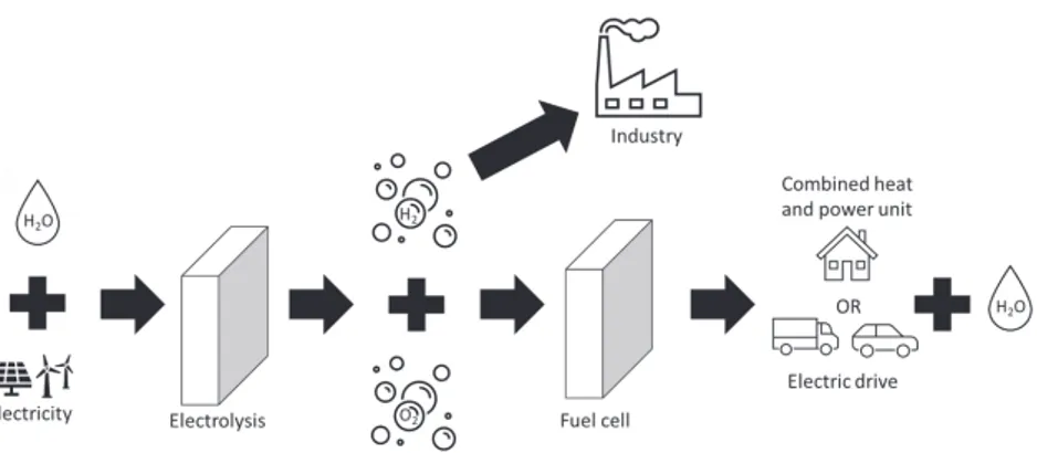
Another option is chemical storage, with hydrogen as the leading alternative. When electricity production is high, water can be split through electrolysis to form hydrogen and oxygen. The hydrogen is then stored in tanks to be utilised when the electricity consumption is increased. There is an energy loss during electrolysis, but during storage, the losses are minimal. After storage, the hydrogen can be converted back to electricity in a fuel cell to power a vehicle or balance the electrical grid, fuel an aeroplane by combustion or be used as a reactant in chemical processes (Figure 1). The International Energy Agency has made a report on the development of hydrogen production and utilisation. They found that only 0.36 Mt hydrogen was produced by electrolysis or other low carbon production routes in 2019, while the sustainable development scheme is a production of 7.92 Mt hydrogen year 2030. This requires a massive scale-up involving significant investments as well as technology improvements[1].
2
The EU has made a hydrogen strategy as part of their European Green Deal. This is based on hydrogen accounting for almost 2 % of the EU’s energy consumption, mainly used to produce chemicals. 96 % of this hydrogen is produced from oil and gas, causing CO2 emissions. To reduce the emissions, the strategy states that the EU will install 6 GW of electrolyser capacity by 2024 and add to this to reach 40 GW by 2030[2]. One of the goals in the EU’s strategy is to boost the demand for clean hydrogen both from industry and from the mobility sector.
One of the industry sectors focusing on hydrogen is the metal production industry, especially iron and steel producers. In steel production, coal is used to reduce the iron ore to pure iron, with CO2 as a by-product. By exchanging coal with hydrogen, the emissions are avoided, given that the hydrogen is produced with green energy. A pilot plant producing steel using hydrogen is under development in a joint venture by the Swedish companies SSAB, LKAB and Vattenfall[3]. A new steel producer recently announced that they will start producing steel based on the same technology[4].
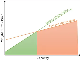
Although batteries are paving the path for the electrification of vehicles, the discussion about how to fully electrify all vehicles is ongoing. While batteries have higher efficiency than fuel cells, the energy density is lower when a larger amount of energy is needed as the whole battery needs to become bigger, while with a fuel cell adding larger or additional hydrogen tanks are sufficient[5]. It also comes with the advantage of a much shorter refuelling time. Therefore, for long-range transport and some construction machines, fuel cell electric vehicles are the most feasible solution with today’s technology to eliminate the use of fossil fuels (Figure 2)[6].
Toyota has for a long time been leading in the fuel cell electric vehicle development, with the Toyota Mirai fuel cell electric car being available on the commercial market today[7]. However, as battery electric vehicles have increased their range, the focus of FCEV has turned towards more long-range and heavy-duty vehicles, where large storage capacity and short refuelling times are important factors. Daimler Truck and Volvo Group recently signed a Joint Venture to develop fuel cells for vehicle applications[8]. Nikola is a new company focusing on electric trucks powered by fuel cells and batteries[9]. There are even test projects with fuel cell driven boats[10,11] and short-range aeroplanes [12,13]. However, most of these are at a developmental and prototyping stage, and there is some more time before FCEV’s reach mass production at a large scale.
1.1 POLYMER ELECTROLYTE MEMBRANE FUEL
CELLS
There are several types of fuel cells, characterised by their different electrolyte materials (Figure 3). The PEMFC has the advantage of having a solid electrolyte as opposed to the alkaline fuel cell and the molten carbonate fuel cell while keeping low temperatures compared to the solid oxide fuel cell. This means that the PEMFC can be made very compact and does not need a lot of energy for heating before starting.
Therefore, it has been pointed out as a good alternative for batteries for the electrification of vehicles.
Figure 2: The scaling of fuel cell and battery weight, size and prize with respect to
capacity. Adapted from [5].
Toyota has for a long time been leading in the fuel cell electric vehicle development, with the Toyota Mirai fuel cell electric car being available on the commercial market today[7]. However, as battery electric vehicles have increased their range, the focus of FCEV has turned towards more long-range and heavy-duty vehicles, where large storage capacity and short refuelling times are important factors. Daimler Truck and Volvo Group recently signed a Joint Venture to develop fuel cells for vehicle applications[8]. Nikola is a new company focusing on electric trucks powered by fuel cells and batteries[9]. There are even test projects with fuel cell driven boats[10,11] and short-range aeroplanes [12,13]. However, most of these are at a developmental and prototyping stage, and there is some more time before FCEV’s reach mass production at a large scale.
1.1 POLYMER ELECTROLYTE MEMBRANE FUEL
CELLS
There are several types of fuel cells, characterised by their different electrolyte materials (Figure 3). The PEMFC has the advantage of having a solid electrolyte as opposed to the alkaline fuel cell and the molten carbonate fuel cell while keeping low temperatures compared to the solid oxide fuel cell. This means that the PEMFC can be made very compact and does not need a lot of energy for heating before starting.
Therefore, it has been pointed out as a good alternative for batteries for the electrification of vehicles.
Figure 2: The scaling of fuel cell and battery weight, size and prize with respect to
4
As the name implies, the PEMFC has a polymer electrolyte. There are two main types of polymer electrolytes for fuel cells, proton conductive and anion conductive. Fuel cells using the latter are called anion exchange membrane fuel cells (AEMFC). AEMFCs are at a lower technology readiness level as compared to the proton exchange membrane and will not be discussed in this thesis. The proton exchange membrane is most commonly made of a perfluorosulfonic acid polymer (PFSA). High-temperature PEM (HT-PEM) is also an emerging technology on the fuel cell market, where the polymer membrane is based on polybenzimidazole doped with phosphoric acid. This membrane can sustain temperatures up to 120 °C, but durability is an issue also here, and this thesis will focus on the PFSA based PEMFC. The membrane is placed in the centre of the cell (Figure 4). On each side is a catalyst layer (CL). It is in the CL the following electrochemical reactions occur:
Anode: 𝐻𝐻𝐻𝐻2→ 2𝐻𝐻𝐻𝐻+ + 2𝑒𝑒𝑒𝑒− (1)
Cathode: 12 𝑂𝑂𝑂𝑂2+ 2𝐻𝐻𝐻𝐻++ 2𝑒𝑒𝑒𝑒−→ 𝐻𝐻𝐻𝐻2𝑂𝑂𝑂𝑂 (2)
Total: 𝐻𝐻𝐻𝐻2+
1
2 𝑂𝑂𝑂𝑂2→ 𝐻𝐻𝐻𝐻2𝑂𝑂𝑂𝑂 (3)
Figure 3: Overview of the different types of fuel cells. Adapted from Steele and
Heinzel [14].
4
As the name implies, the PEMFC has a polymer electrolyte. There are two main types of polymer electrolytes for fuel cells, proton conductive and anion conductive. Fuel cells using the latter are called anion exchange membrane fuel cells (AEMFC). AEMFCs are at a lower technology readiness level as compared to the proton exchange membrane and will not be discussed in this thesis. The proton exchange membrane is most commonly made of a perfluorosulfonic acid polymer (PFSA). High-temperature PEM (HT-PEM) is also an emerging technology on the fuel cell market, where the polymer membrane is based on polybenzimidazole doped with phosphoric acid. This membrane can sustain temperatures up to 120 °C, but durability is an issue also here, and this thesis will focus on the PFSA based PEMFC. The membrane is placed in the centre of the cell (Figure 4). On each side is a catalyst layer (CL). It is in the CL the following electrochemical reactions occur:
Anode: 𝐻𝐻𝐻𝐻2→ 2𝐻𝐻𝐻𝐻+ + 2𝑒𝑒𝑒𝑒− (1)
Cathode: 12 𝑂𝑂𝑂𝑂2+ 2𝐻𝐻𝐻𝐻++ 2𝑒𝑒𝑒𝑒−→ 𝐻𝐻𝐻𝐻2𝑂𝑂𝑂𝑂 (2)
Total: 𝐻𝐻𝐻𝐻2+
1
2 𝑂𝑂𝑂𝑂2→ 𝐻𝐻𝐻𝐻2𝑂𝑂𝑂𝑂 (3)
Figure 3: Overview of the different types of fuel cells. Adapted from Steele and
The CL is either coated onto the membrane, forming a catalyst coated membrane (CCM), or coated onto the gas diffusion layer (GDL), creating a gas diffusion electrode (GDE).
The GDL is a porous layer between the catalyst and the flow plates, ensuring electrical contact to the CL while enabling mass transport of the reactants and products of the reaction.
Finally, the flow plates are at the edge of each cell. The flow plates have inlet and outlet holes for the gases, with a pattern of channels between to ensure even distribution across the cell area. In a typical fuel cell stack, around 400 cells are stacked in series. Two flow plates will then be welded together to form a bipolar plate (BP), with the anode of one cell on one side and the cathode of the neighbouring cell on the other.
The following sections will cover each component of the PEMFC in more detail.
The bipolar plate
The bipolar plates ensure mechanical stability in the stack, works as a current collector, has a crucial role in separating the gas from the anode side of one cell and the cathode side of the other, and distributing the gases evenly over the cell area. Furthermore, channels between the two plates forming the bipolar plates are often used to circulate coolant to remove heat produced in the reactions. The
Figure 4: Schematic of the cross-section of a PEMFC, adapted from [15].
The CL is either coated onto the membrane, forming a catalyst coated membrane (CCM), or coated onto the gas diffusion layer (GDL), creating a gas diffusion electrode (GDE).
The GDL is a porous layer between the catalyst and the flow plates, ensuring electrical contact to the CL while enabling mass transport of the reactants and products of the reaction.
Finally, the flow plates are at the edge of each cell. The flow plates have inlet and outlet holes for the gases, with a pattern of channels between to ensure even distribution across the cell area. In a typical fuel cell stack, around 400 cells are stacked in series. Two flow plates will then be welded together to form a bipolar plate (BP), with the anode of one cell on one side and the cathode of the neighbouring cell on the other.
The following sections will cover each component of the PEMFC in more detail.
The bipolar plate
The bipolar plates ensure mechanical stability in the stack, works as a current collector, has a crucial role in separating the gas from the anode side of one cell and the cathode side of the other, and distributing the gases evenly over the cell area. Furthermore, channels between the two plates forming the bipolar plates are often used to circulate coolant to remove heat produced in the reactions. The
6
technical targets set by the US Department of Energy (DOE) has been widely accepted as the materials requirements for the PEMFC components and are listed in Table 1 for the bipolar plate[16]. Although the goals were set for 2020, the targets have not been updated. However, while the targets may be reached separately, meeting all the targets on durability and performance in a cost-effective way that can be efficiently scaled up is yet to be achieved, and so the tabulated targets are still relevant.
Table 1 US Department of Energy 2020 Technical Targets for Bipolar Plates[16]
Characteristic Unit 2020 Target
Cost $/kWnet 3
Plate weight Kg/kWnet 0.4
H2 permeation coefficient Std cm3/(sec cm2Pa) <1.3x10⁻¹⁴
Corrosion, anode µA/cm2 <1, no active peak
Corrosion, cathode µA/cm2 <1
Electrical conductivity S/cm >100
Interfacial contact resistance Ω cm2 <0.01
Flexural strength MPa >25
Forming elongation % 40
Graphite has been a safe choice for bipolar plate material due to its chemical stability and excellent conductivity, meeting the requirements on corrosion, conductivity, and interfacial contact resistance (ICR). However, the graphite plates need to be thick to also meet the requirements of mechanical strength and hydrogen permeation. Furthermore, the cost of graphite bipolar plates increases due to the expensive machining needed to make the flow fields[17]. Metallic bipolar plates have therefore taken an increasing part of the PEMFC market as the cost and size of the stack is crucial when the automotive market is the end use. The metallic bipolar plates can be easily formed and meets the requirements on mechanical strength and hydrogen permeation even with thicknesses down to 0.1 mm. The corrosion of metals such as stainless steel must however be kept at a minimum, as the metal ions produced during corrosion contribute to degradation of the membrane[18].
Stainless steel is the most studied metal for the bipolar plate. Wang et al. studied four different stainless steel alloys in a simulated PEMFC environment and found that increasing the chromium content results in improved performance[19]. However, uncoated stainless steels have an ICR around 100 mΩ cm2, 10 times
higher than the DOE target[20]. Aluminium[21] and titanium[17] are also studied as material for bipolar plates, but the ICR is a problem due to the passive layer on the surface also for these metals. A conductive coating or surface treatment is therefore needed for the bipolar plates. Toyota announced in 2015 that they were switching from stainless steel to titanium bipolar plates, as this allowed them to use an amorphous carbon coating instead of gold as was used on the stainless steel[7], despite the higher cost of the substrate.
1.1.1.1 Bipolar plate coating
A method to increase the conductivity of the metal is to modify the surface layer through enriching it in alloying elements. Wang et al. studied thermal nitriding of stainless steel 349. CrN was formed, however, while a control coupon of NiCr produced a uniform CrN layer, particles of CrFeN were formed on 349, and while the ICR was significantly reduce, the nitridation did not improve corrosion resistance[22]. Tian et al. formed a continuous nitride layer on the surface of SS 304L, reducing the ICR and passive current density[23,24]. Cho et al. chromized SS316L by pack cementation and found an improvement in corrosion resistance, while the ICR was similar to the stainless steel[25]. Wang et al. have studied the incorporation of several different metals into the surface of SS 304. Plasma surface diffusion of niobium, molybdenum and tungsten improved both ICR and corrosion resistance to levels with niobium achieving results just above the DOE goals[26–28]. Brady et al. studied the effect of nitriding on a ferritic steel, stamped and laser welded to form a bipolar plate. Low contact resistance, corrosion current densities and a reduction in high frequency resistance in a single PEMFC was achieved. However, of the two nitriding processes, only one gave as good corrosion protection of the stamped plate compared to the flat coupons as an effect of the cold deformation[29].
While metallic coatings like gold, platinum and iridium gives the required ICR and corrosion resistance, the price is too high. Conductive ceramic coatings such as TiN[30], conductive polymers like polyaniline (PANI), carbon-based coatings[31], and composites of the three are all currently researched as alternatives for PEMFC BPs.
Conductive ceramics are typically produced by physical vapour deposition (PVD). A contact layer of Ti or Cr is often deposited on the substrate to ensure good adhesion, and because a bilayer structure is less likely to have defects such as pinholes go through to the substrate. Nitrides such as TiN[30,32,33] and carbides such as CrC[34,35], TiC[36], MoC[37] are well studied coatings. Multiple metals may also be added like TiAlN [30], CrMoN[38], TiNbN[39]. MAX-phase coatings and nanocomposite coatings based Ti-Si-C have been proven efficient for fuel cell applications[40]. Ti3AlC2, where the deposited coating is annealed to achieve
crystalline phase have also been studied due to the chemical stability and high thermal and electric conductivity[41]. Intergranular corrosion has been observed for TiC. Li et al. proposed that the TiC corrosion mechanism is initiated by the reaction of TiC and HF, a product of membrane degradation[36].
The carbon-based coatings are also produced by PVD. To ensure good adhesion to the steel substrate, a contact layer of Ti or Cr is also here deposited, with an addition of a transition layer of TiC before the carbon layers. Li et al. studied the performance of an amorphous-C coating without a contact and transition layer and found that the coating was intact after 12 h potentiostatic test, however, growth of chromium oxide on the SS 316L substrate show that the substrate was not protected against the environment. PVD parameters such as argon flow[42] and bias voltage[31] affect the performance of the coating. Feng et al. found pitting occurring at boundary of carbon granules of a C/CrN coating[43]. Zhang et al. varied the bias voltage to produce a multi-layered coating with improved corrosion resistance compared to the monolayered[44,45]. The same research
8
group further found than thin amorphous carbon coatings of a thickness of only 69 nm and a deposition time of 15 minutes gave adequate corrosion resistance and ICR[46]. Zhang et al. doped the amorphous-C layer with Cr and Ag, resulting in a coating meeting the DOE requirement for corrosion resistance, and ultra-low ICR[47].
Cooper and El-Kharouf produced a TiN-PANI bilayer coating through electrodeposition, reaching adequate corrosion resistance, although further work to reduce the ICR is required[48]. Jiang et al. produced a polypyrrole-graphite oxide composite coting also by electrodeposition. The corrosion resistance of the polypyrrole coating was improved by the graphite oxide, but ICR measurements were not performed[49].
1.1.1.2 Bipolar plate forming
Graphite plates are very brittle and must therefore be made thicker to ensure mechanical stability and low gas permeation[50]. Furthermore graphite or composite graphite plates are formed either by machining or compression moulding[51,52]. The increased thickness, weight and more complex forming makes the graphite plates more expensive and less suitable for PEMFC application, especially for vehicles. A major advantage of the metallic bipolar plates is the ease of forming even thin sheets without causing loss of mechanical properties.
There are several techniques used to form the metallic plates, but hollow embossing, and hydroforming are leading for commercial bipolar plates[52]. Roll hollow embossing, rubber pad stamping and different methods of hot pressing are also being researched[20]. For metallic plates, an effective cost-reducing element is continuous roll-to-roll coating of sheet metal and forming it in a coated condition. This greatly reduces the production cost compared to coating the formed bipolar plates, however, ensuring that no damage of the coating occurs during coating can be difficult[52]. Novalin et al. found that carboxide droplets could be found on top of the protective coating due to laser cutting of edges and holes of the plate after coating. These unstable deposits dissolved during PEMFC operation and lead to critical levels of membrane contamination[53].
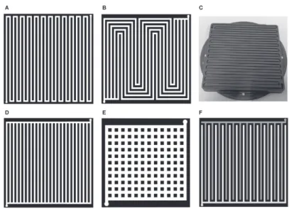
The flow field design is crucial to aid in the even transport of gases to the active area, so that no local starvation issues occur, as well as transport of water out of the cell so that there is no water accumulation hindering the gas transport, and consequently minimising the mass transport losses of the PEMFC, increasing the efficiency[50]. Sauermoser et al. and Wilberforce et al. has written thorough reviews on the different flow field designs[50,54]. The most common flow field design is the serpentine flow field (Figure 5a,c), where a single flow field starting at an inlet, covers the whole area of the plate by narrow bend forming a serpentine pattern and ending at an outlet on the other end of the plate. This design is common due to the good water management as droplets are forced towards the outlet in the single flow field, and has been shown to enhance performance for small cells[54]. However, for bigger cells the long channel length leads to depletion of reactant towards the end and there is a significant pressure drop[54]. The serpentine flow field can be modified by adding multiple channels in parallel (Figure 5b), reducing the length of the channels. Other conventional designs are parallel design (Figure 5d) where all channels go from one side to the
other, with a single channel at each end connecting them, pin design (Figure 5e) where pins are evenly distributed over the active area and the gas travels in between these pins, and interdigitated design where the channels are not connected, forcing the gas into the GDL to get to the outlet (Figure 5f)[50].
Bio-mimetic flow plates, mimicking the air flow in lungs, or water transport on the surface of leaves are being researched[54,55], as is spherical designs, and mesh or porous materials for flow plates[50]. Toyota has shared their 3D fine mesh flow field structure for optimal gas transport towards the catalyst layer and water transport out of the cell[7]. However, there is a trade-off between complex geometries giving increased cell performance, and cost of production[52]. In addition to the gas flow fields, bipolar plates are produced so that two half plates can be welded together, and coolant can be circulated in the gaps between the plates to keep a stable temperature in the stack[52], removing the heat produced by the electrochemical reactions. Further aspects such as the cross-section geometry of the channel, the ratio of land/channel and the ratio between channel width and depth are equally very important to ensure a well-functioning bipolar plate[54].
Li et al. studied the effect of strain and strain rate on the corrosion properties of SS 316L and found that the best corrosion protection was found at 20% strain and increasing strain rate decrease the passive current density. This is connected with the maximum austenitic phase ratio found at these conditions, and a resulting passive layer with the maximum Cr2O3 content[56].
Figure 5: Flow field designs: serpentine (A and C), multi-channel serpentine (B),
10
The gas diffusion layer
The GDL, much like the bipolar plate, has several functions in the PEMFC. Morgan and Datta identified the five most important properties of a well-functioning GDL[57]: 1. Reactant permeability 2. Product permeability 3. Electrical conductivity 4. Thermal conductivity 5. Mechanical support
The reactant permeability is achieved by porosity and is facilitated by good product permeability avoiding water accumulation in the GDL. The product permeability is ensured by a hydrophobic treatment by PTFE. To meet the requirements on electrical conductivity, the GDL is made of carbon fibres and particles. To obtain the mechanical stability needed, a binder is used. The GDL is typically between 100 to 300 µm thick[58].
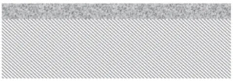
The GDL connects the bipolar plate to the catalyst layer. While the flow fields on the bipolar plate are in the millimetre range, the catalyst layer contains nanoparticles supported on micrometre size carbon supports. The gradient in size must be mirrored in the GDL structure. The carbon fibres give a course structure, and a microporous layer is therefore added on top (Figure 6). The microporous layer ensures a smooth surface towards the CL.
The small, hydrophobic pores of the microporous layer ensure that water is transported away from the catalyst layer towards the bipolar plate. However, as shown by Li et al., the water content in the microporous layer increases due to carbon corrosion during fuel cell operation[59].
The catalyst layer
The catalyst layer contains catalyst particles, typically Pt or Pt-alloy nanoparticles supported on carbon, with an addition of binder as well as an ionomer to achieve proton conduction in the layer (Figure 7). For the electrode reactions (Equation 1 and 2) to occur, both the catalyst with electronic contact, open porosity for the reactants, and ionomer for proton conduction must be present at the same time. The boundaries where all of the mentioned phases are present are called the triple phase boundary[60].
The catalyst is one of the main areas of research for the fuel cell, as the stability of the catalyst is crucial for the durability of the PEMFC, and because of the rare and costly Pt used. The catalyst represents 41 % of the cost of a fuel cell stack[61]. The Pt particles are typically synthesised by the solvothermal method. When comparing different Pt based catalysts, the current densities are normalised with respect to the Pt-mass. The electrochemical surface area (ECSA) is also a parameter used to compare catalysts, giving the active area towards the electrochemical reaction[62]. Through optimising the Pt to expose the most active crystallographic planes[63], alloying with other metals[64–66], or
enclosing the particles in a protective organic layer[67,68], the amount of Pt required while achieving high activity and durability can be minimised.
Alloying of Pt is utilised among others by Toyota, who employs PtCo catalysts in their fuel cell electric vehicle[7]. Other transition metals such as Ni, Fe, Co, and Cu have also been explored. The Pt-transition metal nanoparticles are designed to have a Pt rich shell by etching or dissolving the less electrochemically stable transition metal. The resulting core shell structure has been shown to increase the activity of Pt thorough a strain effect[69].
As mentioned, the Pt is deposited on a support, most commonly carbon. Optimising the support is a key part of optimising the catalyst layer. Carbon is often added to the Pt precursor prior to the reduction. As a result, some Pt particles may be incorporated inside the support, thus not becoming electrochemically active. Doping the carbon support with N has been proven to improve the corrosion resistance of the carbon, and result in smaller and more well dispersed Pt particles[70–72]. Carbon nanotubes[73–75], carbon nanowires[76,77], and metal oxides[78–80] have been proposed as alternatives or additions to carbon black. Porous carbon supports increase the durability of the Pt catalyst[81,82].
The ionomer distribution in the catalyst layer is important to ensure proton conduction while at the same time not hindering transport of the reactants. While porous carbon supports increase the catalyst stability, the ionomer contact may be limited when catalyst particles subside inside pores[83]. The catalysts are often enclosed in a thin ionomer film. Chen et al. studied the diffusion of oxygen through thin ionomer films. Both the rate of proton conduction along the film and oxygen diffusion through the film was decreased with decreased thickness[84]. Cetinbas et al. studied a commercial porous support catalyst layer by X-ray computed tomography combined with transmission electron microscopy and Brunauer-Emmet-Teller gas adsorption porosimetry to build a model for oxygen diffusion in the catalyst layer. They found that the ECSA increased with increasing relative humidity due to water filling the pores, ensuring proton transport. The
Figure 7: A catalyst layer with Pt-particles (yellow) on a carbon support (grey) with
ionomer (blue).
enclosing the particles in a protective organic layer[67,68], the amount of Pt required while achieving high activity and durability can be minimised.
Alloying of Pt is utilised among others by Toyota, who employs PtCo catalysts in their fuel cell electric vehicle[7]. Other transition metals such as Ni, Fe, Co, and Cu have also been explored. The Pt-transition metal nanoparticles are designed to have a Pt rich shell by etching or dissolving the less electrochemically stable transition metal. The resulting core shell structure has been shown to increase the activity of Pt thorough a strain effect[69].
As mentioned, the Pt is deposited on a support, most commonly carbon. Optimising the support is a key part of optimising the catalyst layer. Carbon is often added to the Pt precursor prior to the reduction. As a result, some Pt particles may be incorporated inside the support, thus not becoming electrochemically active. Doping the carbon support with N has been proven to improve the corrosion resistance of the carbon, and result in smaller and more well dispersed Pt particles[70–72]. Carbon nanotubes[73–75], carbon nanowires[76,77], and metal oxides[78–80] have been proposed as alternatives or additions to carbon black. Porous carbon supports increase the durability of the Pt catalyst[81,82].
The ionomer distribution in the catalyst layer is important to ensure proton conduction while at the same time not hindering transport of the reactants. While porous carbon supports increase the catalyst stability, the ionomer contact may be limited when catalyst particles subside inside pores[83]. The catalysts are often enclosed in a thin ionomer film. Chen et al. studied the diffusion of oxygen through thin ionomer films. Both the rate of proton conduction along the film and oxygen diffusion through the film was decreased with decreased thickness[84]. Cetinbas et al. studied a commercial porous support catalyst layer by X-ray computed tomography combined with transmission electron microscopy and Brunauer-Emmet-Teller gas adsorption porosimetry to build a model for oxygen diffusion in the catalyst layer. They found that the ECSA increased with increasing relative humidity due to water filling the pores, ensuring proton transport. The
Figure 7: A catalyst layer with Pt-particles (yellow) on a carbon support (grey) with
12
oxygen diffusion through the ionomer found by the model correlate well with the experimental results of Chen et al.[83].
Research on alternatives to Pt and other platinum group metals are a hot topic, with single atom metal catalysts in the focus[69]. Co-doped carbon with nitrogen and a transition metal is synthesised through pyrolysis. Fe-N-C and Co-N-C has proven to achieve potentials similar to Pt/C[85,86], however, the durability must be improved, and further optimisation of the incorporation into the PEMFC is still needed.
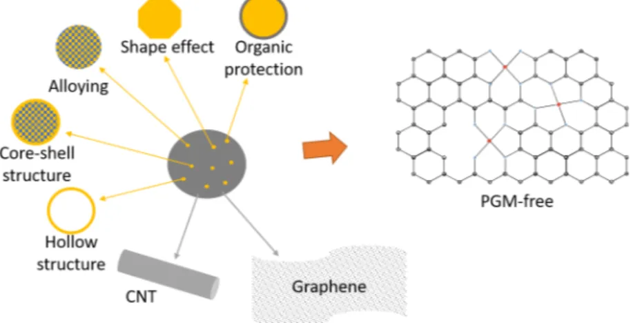
The main research areas of PEMFC catalysts are summarized in Figure 8, and more details on the latest research on catalysts for PEMFC can be found in Supplement I.
Figure 8: The different improvement strategies for PEMFC catalyst layers.
1.1.3.1 Electrodeposited catalysts
An alternative method to produce the catalyst is through electrodeposition. The GDL can be used as a substrate for the deposition to directly produce gas diffusion electrodes. Pt is electrodeposited onto the GDL by immersing the GDL in an electrolyte containing Pt salts, together with a counter electrode and a reference electrode. By applying a potential between the counter electrode and the GDL, the Pt will be deposited. In the PEMFC, catalyst nanoparticles are wanted. The particle size from the electrodeposition can be effectively reduced by switching from direct current to pulsed current, as the higher current density used by pulse electrodeposition increases the nucleation rate, and the pulse off time allows for mass transport of new Pt ions to the substrate[87,88]. Although the grain size is not as small as particles produced by other methods, Fouda-Onana et al. produced Pt particles of size 50 nm and found that the utilization rate of the electrodeposited Pt particles were higher due to all particles having electronic, mass and ionic transport conditions[89].
When the microporous layer of the fuel cell is used as a substrate, the hydrophobicity of the MPL may hinder the electrolyte from entering the pores and limit the deposition. Egetenmeyer et al. therefore pre-treated the MPL by
12
oxygen diffusion through the ionomer found by the model correlate well with the experimental results of Chen et al.[83].
Research on alternatives to Pt and other platinum group metals are a hot topic, with single atom metal catalysts in the focus[69]. Co-doped carbon with nitrogen and a transition metal is synthesised through pyrolysis. Fe-N-C and Co-N-C has proven to achieve potentials similar to Pt/C[85,86], however, the durability must be improved, and further optimisation of the incorporation into the PEMFC is still needed.
The main research areas of PEMFC catalysts are summarized in Figure 8, and more details on the latest research on catalysts for PEMFC can be found in Supplement I.
Figure 8: The different improvement strategies for PEMFC catalyst layers.
1.1.3.1 Electrodeposited catalysts
An alternative method to produce the catalyst is through electrodeposition. The GDL can be used as a substrate for the deposition to directly produce gas diffusion electrodes. Pt is electrodeposited onto the GDL by immersing the GDL in an electrolyte containing Pt salts, together with a counter electrode and a reference electrode. By applying a potential between the counter electrode and the GDL, the Pt will be deposited. In the PEMFC, catalyst nanoparticles are wanted. The particle size from the electrodeposition can be effectively reduced by switching from direct current to pulsed current, as the higher current density used by pulse electrodeposition increases the nucleation rate, and the pulse off time allows for mass transport of new Pt ions to the substrate[87,88]. Although the grain size is not as small as particles produced by other methods, Fouda-Onana et al. produced Pt particles of size 50 nm and found that the utilization rate of the electrodeposited Pt particles were higher due to all particles having electronic, mass and ionic transport conditions[89].
When the microporous layer of the fuel cell is used as a substrate, the hydrophobicity of the MPL may hinder the electrolyte from entering the pores and limit the deposition. Egetenmeyer et al. therefore pre-treated the MPL by
O2/Ar plasma to have a hydrophilic surface[88]. They further experimented with the gradient of ionomer added to the CL after electrodeposition, with the most ionomer closest to the membrane and found that the gradient has a significant improvement on the PEMFC performance[88].
Alloying Pt with other metals can be performed by co-electrodeposition. Egetenmeyer et al. deposited Pt-Co, and found that although the alloy outperformed the pure Pt, Pt-Co lacked durability[88]. Sorsa et al. on the other hand found mesoporous Pt-Co to have higher mass activity and durability than electrodeposited Pt, Pt-Ni and PtCu and commercial Pt/C as well as outperform Pt/C in a direct methanol fuel cell[90].
The membrane
The membrane used in the PEMFC is made from a perfluorinated sulfonic acid polymer (PFSA). The polymer has a fluorinated backbone, and sidechains functionalized by sulfonic acid groups[60]. The backbone is hydrophobic, while the functional groups are hydrophilic. Upon humidification of the polymer, the hydrophilic functional groups on the sidechains which naturally cluster together attract the water. The negative SO3- functional groups and the protons forms a dilute acid when hydrated, thus facilitating the proton transport through the membrane[60]. The PFSA membrane can be mechanically reinforced by PTFE, and silica particles can be added to increase the humidity in the membrane, allowing thicknesses down to 25 µm is used[91].
A common problem in the membrane is that the protons can be replaced by other cations such as Fe2+ impurities from the bipolar plates or from the humidified air/fuel stream and balance of plant components. These contaminants will bond to the SO3- group and hinder their ability for proton transport. While protons can easily migrate through the membrane, the mobility of these larger ions is much lower.
Furthermore, hydrogen peroxide can be synthesised at the cathodes, which through the Fenton reaction causes formation of hydroxide radicals. The radicals formed further reacts with the polymer membrane causing degradation and release of HF[92]. Some metal ions such as Fe, Cu and Ti catalyse the Fenton reaction, increasing the degradation rate of the membrane if the ions enter the membrane. Mn and Ce on the other hand mitigates the degradation through radical scavenging[93,94].
The effect of different metal ions has been studied in literature by various methods. Some soak the membrane in an ion-containing solution[95] while others inject salts in the airstream[96,97]. In both cases, it has been shown that concentrations of only 5 ppm metal ions, specifically Fe3+ and Al3+, are critical for the performance of the PEMFC[95,97]. Eom et al. performed a single-cell test using AISI 316L stainless steel and found that the degradation rate doubled compared to the use of graphite bipolar plate. Post analysis of the membrane found significant amounts of iron in the membrane, and the proton conductivity of the membrane was reduced by more than a factor of three after the test[98].
14
1.2 FUEL CELL ANALYSIS AND ACCELERATED
STRESS TESTS
Ex-situ tests of bipolar plate materials and coatings
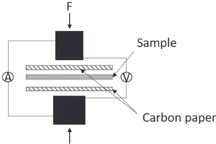
For the bipolar plates, a major part of the research revolves around new coatings. Experiments to characterize the properties of the coatings are most commonly done on flat samples, as this is required for the ICR measurement and simplifies the measurement setup in an electrochemical cell. The DOE requirements presented in Table 1 largely refers to tests on flat coupons[16]. ICR measurements are performed by sandwiching a coupon coated on both sides between two GDLs, and compressing this stack between two pure copper or gold coated copper probes (Figure 9) [19,99]. When measuring contact resistance, it is important to remember that no surface is completely flat, and that the surface roughness of the two contacting surfaces results in the current passing through the contact points between the two materials. This is especially important to consider when using GDLs in the measurement as the contact area between the GDL and sample increases upon increasing pressure. Using this method, the pressure on the materials can be adjusted to simulate that in a fuel cell to reproduce the contact area. Temperature and humidity are however not simulated in these measurements that are performed at room temperature. A four-point probe measurement technique is used, where two probes are used to apply the current, and the other two measure the potential. In this way, the resistance of the cables can be excluded.
However, this test is not applicable to formed plates, and can therefore not be used to test the quality of a coating on a bipolar plate. Shaigan et al. proposed combining the methodology of a single probe test from the ASTM B539 and B667 standards to test contact resistance on formed plates[51]. This will allow for testing ICR independent of the sample geometry, although the pressure applied in this case will not be the same as in a PEMFC, and the ICR measured will be measured between the sample and probe, and not between the sample and the GDL.
For metallic bipolar plates, the other important parameter to test is corrosion, or corrosion resistance. The electrochemical tests referenced by the DOE is performed in dilute H2SO4 of pH 3, with an addition of 0.1 ppm of HF, at 80°C [16]. This is an environment set to simulate the PEMFC environment. However, it is not uncommon in research to use an accelerated environment where the electrolyte concentrations are increased to 0.5 M H2SO4 and 2 ppm HF, still at 80°C. Air or oxygen is bubbled through the electrolyte to simulate the cathode environment, while the electrolyte is deaerated or bubbled with hydrogen to simulate the anode environment. Feng et al. studied the effect of changing pH on the potentiodynamic polarisation curve of SS316L and found that at pH 3-6 the stainless steel showed no active peak, while increasing the acidity to 0.5 M or 1 M H2SO4 gave active peaks and a passive current density an order of magnitude larger compared to the higher pH. Similarly the current density for potentiostatic measurements increase significantly when going from pH 3, which has a low average current density, but with a lot of noise due to pitting, to 0.5 and 1 M H2SO4 which have higher average current densities but less noise due to pitting [100]. Kumagai et al. studied the composition of the passive layer of SS310S by XPS after potenitostatic tests in electrolytes with different pH. They found that while the samples exposed to higher pH showed two oxide layer with the inner enriched in chromium, and the outer enriched in iron, for pH lower than 3.3 only the chromium rich layer could be discerned by XPS, with decreasing thickness with decreasing pH [101].
Lædre et al. studied the effect of halide addition to a 1 mM H2SO4 solution on the polarisation curves of SS316L. While 100 ppm of chloride destabilised the passive layer, 2 ppm of fluoride lowered the current density during a potentiostatic test, however the noise due to pitting increased compared to the solution without halide addition [102]. The choice of electrolyte concentration and additions are therefore key when testing new materials, and care should be taken when comparing results between different publications.
Also the potentials considered for the anode and cathode bipolar plates are important. Hinds et al. measured the corrosion potential of an uncoated stainless steel bipolar plate in situ, and found that the potential of the bipolar plate has only a weak coupling to the potential of the catalyst due to the lack of a continuous liquid layer, hindering ionic transport between the two [103].
PEMFC accelerated stress tests
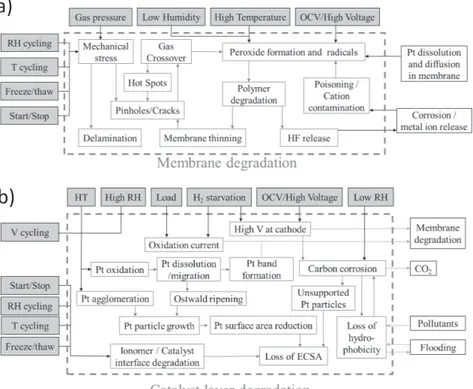
Accelerated stress tests (AST) aim to test the durability of a component or system by exposing it to an environment and operation similar to real-life but designed so that the degradation mechanism is accelerated. This allows to run shorter tests, but still compare the durability of the PEMFC. During PEMFC operation, the cell is exposed to load cycles, temperature changes, relative humidity changes, and start-up and shutdowns. Which of these changes, or which levels are the most corrosive will vary between the components as the materials and exposure is different between them. De Bruijn et al. mapped how specific operating conditions trigger specific degradation mechanism, and how this degradation can be measured for both the membrane and the catalyst[104]. Petrone et al. built onto this to include simple ASTs (Figure 10) [105].
16
When designing an AST for PEMFC, it can be designed to accelerate the degradation of a specific component by increasing the frequency or duration operating under conditions known to be aggressive for the chosen component and material. As an example, the US DOE has proposed a set of tests that are aimed at each of the PEMFC components individually [16]. These types of load cycles have simple repeat units such as square waves or triangle sweeps. Square wave cycles are also used for humidity cycling [105]. This is very useful when developing a component, as the durability can be tested very efficiently, since the ASTs are aimed at specific degradation mechanisms. However, it is very difficult to say anything about the lifetime of the whole system based on these tests, as the operation is very dissimilar to normal operation.
Figure 10: The effect of operating conditions and ASTs on the membrane
degradation (a) and catalyst layer degradation (b) of a PEMFC. Adapted from Petrone et al. [105].
Another way to design the AST is to look to the cycle during normal operation in the end application and increase the frequency of the cycling. This can also be referred to as accelerated load cycles (ALC). An example of this method is the new European drive cycle (NEDC). The NEDC is utilised in a wide range of tests for light-duty vehicles, with both urban driving and motorway driving, acceleration, deceleration, and constant speed. In a report by the EU Fuel Cells and Hydrogen Joint Undertaking, the NEDC is translated from cycling velocity to an ALC based on cycling load to be able to apply it to a single cell PEMFC [106]. Universities and
a)
research institutes across the globe have developed their own ALC protocols based on drive cycles [107]. ALCs for lorries, trucks, planes, trains, ships etc. can similarly be made from drive cycles for the respective vehicle. For stationary applications, a load cycle based on the use must also be made, dependent on whether the PEMFC will be used at a constant load, if the load will vary dependent on the use in a house or if it is back-up power to be used when there is no electricity on the grid. An important factor to consider is how start-up/shut down is handled. The PEMFC anode may during start-up and shutdown be exposed to both hydrogen and oxygen if it is not purged, as oxygen can diffuse through the membrane or enter from the outlet if this is not sealed. The ALC should simulate the start-up and shut-down of the end application as closely as possible, whether it is purging, or if the anode is well sealed as is more likely in an automotive application where there is less space to add purge gas. The off time must also be considered, for example by freeze-thaw cycles as this might significantly affect a humidified membrane, an induces mechanical stresses in the MEA [108]. Having standardized tests for durability is crucial when a new technology is emerging, as this allows for comparison between the different commercial products. For the comparison to work, the test method must be designed so that the results are reproducible between test facilities. For a PEMFC test this puts requirements on the gas purity, temperature, pressure and humidity, cell or stack temperature and the load application. Furthermore, the ALC must be validated so that it is confirmed that the degradation mechanisms in the ALC is the same as those active in the real application, only accelerated. Only if this is true can it be called an accelerated load cycle and be used to evaluate the performance, durability and predict lifetime of a PEMFC.
CHAPTER 2
RESEARCH OBJECTIVE
CHAPTER INTRODUCTION
This chapter first present the purpose and aim of the work performed, leading to the research questions.
2.1
PURPOSE AND AIMAs the production of PEMFCs is upscaled, there is a need for quality control and bridging the gap between research and industry. Within research on the different components, methods to test the critical parameters for the PEMFC has been set so that research from different groups can be compared. However, environments used are designed to accelerate the degradation, with the risk of activating other corrosion mechanisms, and tests are are performed on small, flat samples, and may not be suitable for use for quality assurance in industry. There are also additional material problems occurring during production that are not widely discussed in literature. The aim of this thesis is to start from the research on materials for fuel cells, and study how these materials degrade. Questions to be asked are how the degradation can be detected and characterized, how the degradation of one component affect the other components, and how the though requirements on materials for PEMFC components can be met also in commercial applications, at a competitive cost level.
2.2
RESEARCH QUESTIONSRQ1: How do PEMFC components degrade and how can the degradation be
mitigated?
RQ1.1: What are the critical points for localised corrosion on PEMFC
bipolar plates, and how can it be monitored during in-situ testing?
RQ1.2: How can the Pt catalyst durability be increased while
reducing the amount of Pt?
RQ2: How can the degradation mechanisms of the different components be
detected and monitored in-situ in a polymer electrolyte fuel cell?
RQ3: How should an accelerated stress test be designed to best simulate fuel cell
degradation and be relevant for vehicle applications?
The first research question, with sub-questions, is the focus of the supplements. During durability testing in the supplements RQ2 is also studied as different ASTs are utilised, and polarisation curves and EIS are obtained. This will be further built upon towards answering RQ3 during the further work towards the PhD.
CHAPTER 3
RESEARCH APPROACH
CHAPTER INTRODUCTIONThis chapter describes the methodology, materials and characterization techniques chosen in this work.
3.1
RESEARCH DESIGN AND METHODOLOGYThis work aims to understand the effect of the different materials in a polymer electrolyte fuel cell on the performance of the cell and understand the cause of failure. An experimental research design is therefore chosen. Experimental research follows the positivist approach and is based on a hypothesis, and then testing this through experiments and deductive reasoning[109]. An important factor when doing experimental work is to control all confounding variables to ensure that the measured effect on the dependent variable is caused by the change of the independent variable. Within the fuel cell field, this is fully achieved in the ex-situ experiments. However, there are ongoing discussions concerning if the lab environments and test procedures used are good representations of the conditions in a real fuel cell[18,103]. Additionally, the number of variables in a fuel cell test is too large to ensure that no confounding variables affect the results, and an accepted standard test method is missing[105,107,110]. Therefore, this work aims to perform to ensure both internal and external validity of the results by combinations of in-situ and ex-situ tests and contribute to improving the internal validity of the fuel cell tests.
Research quality assurance
To ensure validity and reliability, several samples are synthesised when the synthesis is in focus to prove the reproducibility. In the analysis, standard procedures are followed when possible and measurements are repeated with different samples of same composition to increase the reliability. The results are compared with references to ensure validity.
The flow plates, commercial gas diffusion electrodes and the membrane are purchased in a batch at the beginning of the work to avoid variance between batches affecting the results.
3.2
MATERIAL AND CELL DESIGNIn this work, the cell house used was a single cell designed at RISE Borås for an earlier project (Figure 11a). It has a geometric area of 2.89 cm2. The endplates are made of stainless steel, and the cell compression is ensured by four screws placed at each corner. For the tests on the bipolar plates, a torque of 1 Nm was
22
used. For the tests on the electrocatalyst, the compression of the cell was first optimised by exchanging the membrane with a Fujifilm Prescale pressure sensitive film provided by CA Mätsystem AB, and the torque was reduced to 0.5 Nm.
The membrane electrode assembly
The membrane used in all experiments is Nafion 212. Material from the same batch was used throughout the work. Gas diffusion electrodes made of 0.3 mg/cm2 Pt on Vulcan deposited on carbon paper was used as a standard when studying corrosion of flow plates. Materials from the same batch of gas diffusion electrodes will be used throughout the work.
For the electrocatalyst work, the cathode catalyst has been produced by electrodeposition of PtNi and PtNiMo onto a gas diffusion layer. The anode catalyst was the commercial gas diffusion electrode described above. The electrodeposition process is described in the next section. The membrane electrode assembly was hot pressed for three minutes at 3 bar pressure and 110°C when electrodeposited catalyst material is used to ensure good contact between the gas diffusion electrode and membrane.
Electrodeposited catalyst
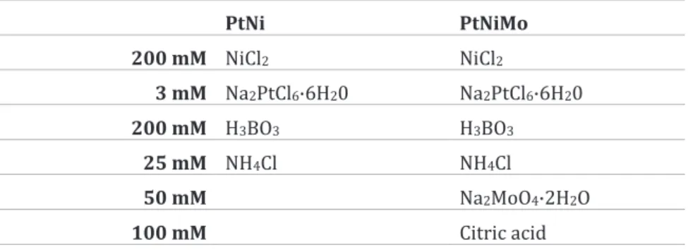
PtNi and PtNiMo nanoparticles were electrodeposited in a standard electrochemical cell. The electrolytes used were prepared as described in Table 2. An Autolab 302N potentiostat was used to control the electrodeposition. A Ag/AgCl reference electrode and a Pt counter electrode were used, and the working electrode was a GDL provided by Freudenberg. The GDL was mounted on a Cu plate to ensure conductivity using polyimide tape, which was also used to isolate the sides and back of the Cu plate. The exposed area of the GDL was 2x2 cm2. Equal mounting was used for electrochemical analysis of the catalyst, while the resulting GDE was trimmed to 1.8x1.8 cm2 for use in the fuel cell.
Table 2: The electrolyte composition for depositon
PtNi PtNiMo 200 mM NiCl2 NiCl2 3 mM Na2PtCl6·6H20 Na2PtCl6·6H20 200 mM H3BO3 H3BO3 25 mM NH4Cl NH4Cl 50 mM Na2MoO4·2H2O 100 mM Citric acid Flow plates
As this work is based on single fuel cells, there is no bipolar plate. Instead, there are monopolar flow plates on the anode and cathode side. The flow plate material
is the same as for the bipolar plate, and it is assumed that the degradation mechanisms are also equal.
The flow plates used in this work has a single serpentine flow field (Figure 11b) formed by hydroforming. The substrate material is stainless steel 316L with a thickness of 0.1 mm. Furthermore, a commercially available coating was chosen, applied on the sheet material prior to hydroforming.
3.3 CHARACTERISATION AND TESTING
PEM fuel cell
Single fuel cell test stations of the type Greenlight Innovation G20 is used for the in-situ fuel cell experiments. The test stations control the flow, humidity and temperature of the inlet gases, the temperature of the cell, and have a built-in potentiostat to run ASTs and polarisation curves. One of the test stations is equipped with an additional potentiostat for electrochemical impedance spectroscopy (EIS). This allows for automated testing of the fuel cells.
Hydrogen was fed to the anode while air was used on the cathode with flow rates of 0.042 and 0.1 Ndm3/min, respectively when testing the catalyst, and 0.05 and 0.1 Ndm3/min when testing the flow plates. Nitrogen was used to purge the system at the beginning and end of the tests. The inlet gasses were heated to 80°C, and the water dew point was set to 65°C resulting in a relative humidity of approximately 50 %. The oven in which the cell was placed held a temperature of 75°C. After heating the system, the fuel cell first went through an activation period to achieve the maximum performance. Subsequently, the initial EIS and polarisation curves were obtained before the AST was started. Polarisation curves were obtained by changing set potential or current and holding for 3 minutes. The current or potential was recorded the last minute and averaged before the potential or current was changed.
a) b)
Figure 11: The (a) single-cell and (b) flow plate used in this work.
is the same as for the bipolar plate, and it is assumed that the degradation mechanisms are also equal.
The flow plates used in this work has a single serpentine flow field (Figure 11b) formed by hydroforming. The substrate material is stainless steel 316L with a thickness of 0.1 mm. Furthermore, a commercially available coating was chosen, applied on the sheet material prior to hydroforming.
3.3 CHARACTERISATION AND TESTING
PEM fuel cell
Single fuel cell test stations of the type Greenlight Innovation G20 is used for the in-situ fuel cell experiments. The test stations control the flow, humidity and temperature of the inlet gases, the temperature of the cell, and have a built-in potentiostat to run ASTs and polarisation curves. One of the test stations is equipped with an additional potentiostat for electrochemical impedance spectroscopy (EIS). This allows for automated testing of the fuel cells.
Hydrogen was fed to the anode while air was used on the cathode with flow rates of 0.042 and 0.1 Ndm3/min, respectively when testing the catalyst, and 0.05 and 0.1 Ndm3/min when testing the flow plates. Nitrogen was used to purge the system at the beginning and end of the tests. The inlet gasses were heated to 80°C, and the water dew point was set to 65°C resulting in a relative humidity of approximately 50 %. The oven in which the cell was placed held a temperature of 75°C. After heating the system, the fuel cell first went through an activation period to achieve the maximum performance. Subsequently, the initial EIS and polarisation curves were obtained before the AST was started. Polarisation curves were obtained by changing set potential or current and holding for 3 minutes. The current or potential was recorded the last minute and averaged before the potential or current was changed.
a) b)
![Figure 4: Schematic of the cross-section of a PEMFC, adapted from [15].](https://thumb-eu.123doks.com/thumbv2/5dokorg/5568482.145475/19.701.259.507.370.764/figure-schematic-cross-section-pemfc-adapted.webp)
![Table 1 US Department of Energy 2020 Technical Targets for Bipolar Plates[16]](https://thumb-eu.123doks.com/thumbv2/5dokorg/5568482.145475/20.701.78.564.244.488/table-department-energy-technical-targets-bipolar-plates.webp)