Room temperature synthesis of transition metal
silicide-conducting polymer micro-composites for
thermoelectric applications
Ujwala Ail, Zia Ullah Khan, Hjalmar Granberg, Fredrik Berthold, Rajasekar
Parasuraman, Arun M. Urnarji, Kerstin Slettengren, Henrik Pettersson and Xavier Crispin
The self-archived postprint version of this journal article is available at Linköping University Institutional Repository (DiVA):
http://urn.kb.se/resolve?urn=urn:nbn:se:liu:diva-136665
N.B.: When citing this work, cite the original publication.
Ail, U., Ullah Khan, Z., Granberg, H., Berthold, F., Parasuraman, R., Urnarji, A. M., Slettengren, K., Pettersson, H., Crispin, X., (2017), Room temperature synthesis of transition metal silicide-conducting polymer micro-composites for thermoelectric applications, Synthetic metals, 225, 55-63.
https://doi.org/10.1016/j.synthmet.2017.01.007
Original publication available at:
https://doi.org/10.1016/j.synthmet.2017.01.007
Copyright: Elsevier
Room Temperature Synthesis of Transition Metal Silicide-Conducting
Polymer Micro-composites for Thermoelectric Applications
Ujwala Ail a, Zia Ullah Khan a, Hjalmar Granberg b, Fredrik Berthold b, Rajasekar Parasuramanc, Arun M Umarji c, Kerstin Slettengren b, Henrik Pettersson b, Xavier Crispin a*
a. Department of Science and Technology, Linköpings Universitet, SE-60174 Norrköping, Sweden b. Innventia AB, Box 5604 , SE-114 86 Stockholm , Sweden
c. Materials Research Centre, Indian Institute of Science, Bangalore 560012, India
*E-mail: xavier.crispin@liu.se
Keywords: TM silicide-PEDOT:PSS composite, NFC microparticles, Chromium disilicide,
Conducting polymer-Inorganic TE composite, Composite thermoelectrics.
Abstract:
Organic polymer thermoelectrics (TE) as well as transition metal (TM) silicides are two thermoelectric class of materials of interest because they are composed of atomic elements of high abundance; which is a prerequisite for mass implementation of thermoelectric (TE) solutions for solar and waste heat recovery. But both materials have drawbacks when it comes to finding low-cost manufacturing. The metal silicide needs high temperature (>1000 οC) for creating TE legs in a device from solid powder, but it is easy to achieve long TE legs in this case. On the contrary, organic TEs are synthesized at low temperature from solution. However, it is difficult to form long legs or thick films because of their low solubility. In this work, we propose a novel method for the room temperature synthesis of TE composite containing the microparticles of chromium disilicide; CrSi2 (inorganic filler) in an organic matrix of
nanofibrillated cellulose- poly(3,4-ethyelenedioxythiophene)-polystyrene sulfonate (NFC-PEDOT:PSS). With this method, it is easy to create long TE legs in a room temperature process. The originality of the approach is the use of conducting polymer aerogel microparticles mixed with CrSi2 microparticles to obtain a composite solid at room temperature under pressure. We
foresee that the method can be scaled up to fabricate and pattern TE modules. The composite has an electrical conductivity (σ) of 5.4 ± 0.5 S/cm and the Seebeck coefficient (α) of 88 ± 9 µV/K,power factor (α2σ) of 4 ± 1 µWm-1K-2 at room temperature. At a tempearture difference of 32 οC, the output power /unit area drawn across the load , with the resistance same as the internal resistance of the device is 0.6 ±0.1µW/cm2.
1. Introduction:
Thermoelectric (TE) energy converters are actively explored because of the global demand for renewable and affordable energy resources. Today’s electricity production through heat engines and turbines waste 55% of the primary energy sources in the form of thermal energy. Waste heat and solar heat constitute an untapped energy source for our society. Thermoelectric generators (TEG) have key advantages over organic Rankine cycle, such as, no moving parts as they are solid-state electronic devices. Another area in need of autonomous energy sources is the emergence of mobile electronic devices with extended concepts such as internet-of-thing and internet-of-everything where many sensors need to be powered in networks. Practical TEGs consist of multiple n- and p-type TE legs connected electrically in series and thermally in parallel. The maximum efficiency of a TEG is proportional to (1+ZT)1/2, where the dimensionless figure of merit ZT, of the material is ZT= α2σT/κ (α,σ, κ and T are
the Seebeck coefficient, electrical conductivity, thermal conductivity and the absolute temperature respectively). Presently the state- of- the- art TEGs are based on inorganic materials. For the low temperature T < 250 ⁰C, alloys based on bismuth telluride, containing elements of moderate to high toxicity such as tellurium, antimony and lead, show ZT up to 1.2 at room temperature [1, 2]. Such, bulk thermoelectric elements prepared by dicing and extrusion are traditionally assembled by pick-and-place methods, have limited cost-effective scalability. Alternative technology based on micro-fabrication involves expensive and complicated processes like lithography and thin-film deposition and is limited to the micro-scale regime [3-6]. Typically, 50% of the cost of a TE module comes from the material and the other half from the manufacturing process. It is thus obvious that the mass implementation of TEGs requires breakthroughs in both material science and engineering. Interesting attempts have been made to propose printing technology to create p- and n-leg with inorganic TE paste of bismuth telluride alloys [3].
One of the potential breakthroughs is related to the discovery that organic conducting polymers display promising TE properties [7, 8]. In addition to their competitive properties with respect to the inorganic counterparts in the temperature below 150 οC, they are composed of naturally abundant elements and well suited for the widespread, well established solution based manufacturing facilities [9]. Among the various conducting polymers, PEDOT derivatives are being explored for their potential use in practical TE applications, due to their tunable σ and low κ [10]. PEDOT with Tosylate or PSS counter ions display interesting TE
properties with the highest reported values for the power factor (1270 W m-1 K-2 ) [11] and ZT
=0.25, [8] 0.31 [12] and 0.42 [13] at room temperature.
There are however two challenges for organic TEs. The first is that the power factor is limited by the low α of these polymers; while the ratio of the electrical to the thermal conductivity is similar to Bi2Te3 alloys [14]. The second bottleneck is that conducting polymer
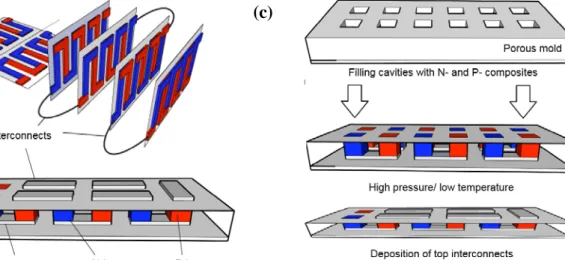
TEs is today optimized as a thin film technology. The reason is that conducting polymers are formulated in inks of low solid content. Lateral architecture has been proposed to create TE modules by printing conducting polymer layers of the order of 1-2 micron thick on a thin substrate, then cutting, folding or rolling the devices (Fig.1a). The advantage is that the temperature gradient, and thus the voltage can be large due to the long legs, but the internal resistance limits the power. To maximize power, it is preferable to keep the classical vertical architecture (Fig. 1b), and create thick vertical legs. The problem is that 10 to 100 printing/drying steps are needed to reach length of the legs of the order of 30-300 µm. This limits the throughput of the manufacturing process. Thick legs are crucial to keep a decently large temperature gradient, note that large temperature gradient also improves the conversion efficiency.
Our goal is to find a method combining mass-manufacturing by printing for patterning legs on large area, and a subsequent low temperature/high pressure treatment for sintering the legs in the devices (Fig.1 c). So, our goal is to avoid high temperature annealing, which leads to cost increase and a dramatic CO2 fingerprint upon manufacturing TEG. For
that, we turn to composites between organic and inorganic TE materials. Inorganic nanoparticles are explored for making inks in application such as printed electronics, but again, the solid content of those inks is very low (few percent in volume) [15, 16]. One other issue of nanocomposites made of inorganic nanoparticles and conducting polymers is the large numbers of inorganic-organic interfaces, at which reside an electronic energy barrier. For TEs, charges should be transported in both the organic and inorganic phases, hence it is challenging to have a pure ohmic contact between the inorganic nanoparticles and the organic conducting matrix. Instead, most of the inorganic nanoparticles possess an insulating oxide layer which leads to large contact resistance, preventing the charge carriers to actually travel in the inorganic domains.
In this work, we found a low temperature method (< 150 οC) to prepare thick leg of a TE micro-composite (schematic shown in Fig. 2a) made of microparticles of chromium disilicide (CrSi2) and microparticles of a conducting aerogel based on cellulose and the
conducting polymer (poly(3,4-ethyelenedioxythiophene)-polystyrene sulfonate; PEDOT:PSS) at temperature below 150 οC. CrSi2 has been chosen for the high natural abundance of its
atomic elements and its resistance to oxidation [17] and high TE power factor (~1 mWm-1K-2) [18]. Fig. 2b, c, and d show the chemical structure of PEDOT:PSS, crystal structure of CrSi2
[19], and chemical structure of NFC respectively. This method avoids the high temperature sintering methods (such as spark plasma sintering or hot uniaxial pressing using induction furnace) necessary for the bulk silicides and secondly the large number of printing steps needed for achieving thick leg with polymer TEs.
2. Experimental Approach
2.1 Formation of pellets, Microstructural and TE Characterization:
The composite pellets were prepared at a pressure of 100 MPa at room temperature for 3 min and were typically 10mm in diameter and 1 mm thick. The surface morphology of powders and pellet samples was studied using scanning electron microscope; SEM (LEO 1550 Gemini) and the elemental compositional analysis was carried out using the attached energy dispersed analysis of X-rays (EDX). The electrical conductivity of the composite pellet was measured at room temperature using the van der Pauw technique. Four carbon point electrodes at the perimeter of the pellet were used in the van der Pauw square geometry (shown in Supporting information Fig. S1) with distance between the adjacent contacts as 5.7 mm. Keithley Source meter 2400 was used for the measurement. The details of the measurements are described in the supporting information. The Seebeck coefficient (α = Voc/∆T) was measured using the
in-house built measurement system at room temperature. Temperature difference (∆T) was applied to the sample by placing it in between a pair of Peltier elements and the corresponding open circuit voltage (Voc) was measured using Keithley Nanovoltmeter 2182A.
Thermocouples were used for the measurement of ∆T.
2.2 Synthesis of NFC-PEDOT:PSS aerogel microparticles:
NFC-PEDOT:PSS microparticles were obtained by spraying a mixed dispersion into liquid nitrogen. NFC was prepared according to the method described in [20] excluding the
carboxymethylation process. The resulting NFC dispersion (conc 2.1 %) and a PEDOT:PSS dispersion (conc 1.3%) was mixed to have a ratio of 50-50 NFC-PEDOT:PSS, using a dispersing instrument (ULTRA-TURRAX T25, IKA®-Werke GmbH & Co. KG). The mixture was then sprayed into liquid nitrogen in a Teflon tape coated Styrofoam box to instantly freeze the NFC-PEDOT:PSS gel particles. The frozen particles were then collected and dried by sublimation, i.e. freeze drying.
3. Results.
CrSi2 is a highly degenerated p-type semiconductor with a narrow forbidden band
gap of 0.29–0.35 eV [21] and its hole mobility is 100 times more than the electron mobility [22]. It’s maximum ZT of 0.2–0.25 around 600 οC [23-25] results in a medium Seebeck coefficient (S= 100–200 µV/K) and a large thermal conductivity (κ= 10 Wm-1 K-1) [26]. In our work, CrSi2 was prepared by melting the elemental Cr (99.995 %) and Si (99.9999 %) in an
arc-melting furnace under argon atmosphere. Ingots were re-melted several times to ensure full homogeneity. Ingot was crushed and the powder was sieved (40 µm mesh) to have particle size of ≤40µm. The scanning electron microscopy (SEM) image of the power is reported in Fig. 3a.The crystalline phase of CrSi2 was confirmed by the x-ray diffraction (Fig. S2) of the
powdered sample. A robust pellet can be formed by applying high pressure (42 MPa) and high temperature (1250 οC) for 5 min to the powder [27]. The resulting pellet has σ of 800 S/cm and α of 110 µV/K (at room temperature). We tried to pelletize the powder at low temperature in order to characterize the TE properties of the CrSi2 powder as a reference measurement since
the goal is to find a manufacturing method to create thick legs at low temperature. But the resulting pellet was so fragile that it collapsed upon manipulation, it was thus impossible to characterize it.
After this brief identification of the properties and challenge to deal with low temperature process of inorganic materials, we hope that using conducting polymer might be a way to create a robust solid pellet of good TE properties. Besides the manufacturing challenge, which is the focus of this manuscript, we want to point out another potential advantage of the composite strategy. Indeed, CrSi2 has a modest ZT value mostly because of its high thermal
conductivity (κ = 12.5 Wm-1K-1). Hence combining with conducting polymer such as
PEDOT:PSS of low thermal conductivity (κ = 1.0 Wm-1K-1) [28], we expect to obtain a solid
is aimed with the intention of possible overall reduction of the κ (due to the polymer incorporation in the silicide matrix), while increasing the α compared to the polymer alone, thus maintaining decent power factor (α2σ ) and going one step towards the optimized TE
property in thick legs obtained by a low temperature process.
The question is how to fabricate such a composite at low temperature. We first investigated various methods to combine the microparticles of CrSi2 fillers with PEDOT:PSS. PEDOT:PSS
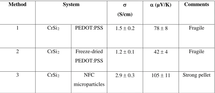
is commercially available as an aqueous dispersion with 1.3 wt. % of polymer. (Trademark: Clevios PH1000). The water dispersion is composed of mostly large particles as indicated by the diffusion light scattering (200-700nm) [29]. In the Method 1 (see Table 1), the CrSi2
powder (particle size ≤ 40 µm) was physically mixed with the aqueous PEDOT:PSS solution in order to have a solid content ratio of 90% CrSi2 and 10% PEDOT:PSS. After evaporation
of the water at 100 οC, the powder obtained was pelletized at a pressure of 100 MPa for 3 min. The pellet was fragile and difficult to handle. The measured σ was 1.5 ± 0.2 S/cm; which is much lower than PEDOT:PSS or CrSi2 alone. The α was 78 ± 8µV/K, i.e. smaller than CrSi2
(110µV/K) but much higher than PEDOT:PSS (20µV/K). Although the high value of α is encouraging, this method is clearly not appropriate for scaling up manufacturing of a TE device since the water evaporation is time consuming. In the Method 2, we first obtain a powder of PEDOT:PSS by freeze drying. The resulting material is an aerogel composed of micro-flakes of PEDOT:PSS (See Fig. 3b). The SEM image reveals that the flakes are about 100 micron in size but very thin (~1micron). The aerogel is fragile and easily smashed into a powder. The PEDOT:PSS powder and CrSi2 powder are then physically mixed and pelletized at room
temperature (P = 100 MPa for 3 min). The resulting micro-composite pellet is again fragile like in the Method 1 and has about the same σ as in the Method 1 (1.2±0.1 S/cm) but lower α (42 ± 4µV/K). So, the Method 2 has the advantage to avoid the slow water evaporation step in the manufacturing of devices but the powder microparticles barely stay together as a solid, despite the very high applied pressure (Fig. 1c). Therefore in the third approach, a binder is required to hold together the CrSi2 microparticles. In Method 3, we first synthesize aerogel
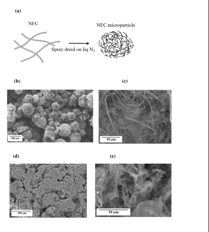
microparticles made of cellulose nanofibrills (NFC). Nanofibrills of cellulose are obtained by the method described in ref [20] excluding the carboxymethylation process. The NFC form a stable dispersion in water (2.1 wt. %). The nanofibers are about 10-20 nm in diameters and of length distribution around 0.5-2 microns. The NFC microparticles were obtained by spray drying the NFC emulsion under liquid N2 (Fig. 4a). The SEM images of the NFC microparticles
distribution from ~10 µm to ~100 µm. At high magnification, one can clearly see that each particle is extremely porous composed of ultrathin walls (Fig. 4c). Applying a low pressure on those microparticles dramatically changes their shape, as illustrated by the SEM image in Fig. 4d, of the smashed NFC microparticles. The magnified image indeed reveals a higher density of cellulose fiber walls (Fig. 4e). Hence the NFC aerogel microparticles are easily deformable in a non-elastic manner and actually form like a continuous solid where it becomes difficult to distinguish the original particles. NFC is a nanofiber scaffold system with remarkably high toughness with a large strain-to-failure [30]. So, we aim at combining both the robust mechanical properties of the nanofibers and the possibility to press aerogel microparticles (aerogel of NFC) in order to hold together the CrSi2 microparticles. In Method 3, the NFC
microparticles were mixed with the silicide powder. The powder mixture (90 wt. % CrSi2, 10
wt. % NFC) was pressed under the similar conditions as the previous methods (T= room temperature, P=100 MPa for 3 min) and this time results in a strong pellet with a σ of 2.9 ± 0.3 S/cm and a α of 105 ± 11 µV/K; which is almost the α of a hot pressed pellet of CrSi2
(110 µV/K). Hence even if the NFC is an electrical insulator, the conductivity is as high as with the PEDOT:PSS alone; which indicates the key role of having a good binder to keep the CrSi2 close to each other.
Though NFC aerogel microparticle seems to play the role of mechanical binder, it is an electrical insulator that actually forms insulating layer between the CrSi2 particles, thus
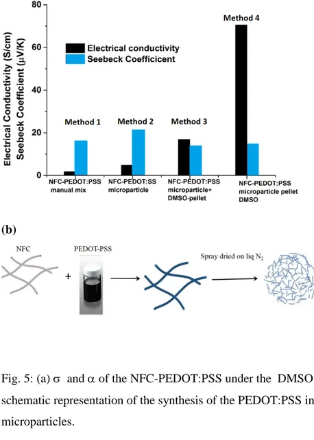
limiting the electrical contact between the metal silicide microparticles. Hence, in this section, we discuss various strategies to make those NFC aerogel to electrically conduct by adding PEDOT:PSS into them. Interestingly, we demonstrated recently the affinity of PEDOT:PSS water dispersion to absorb into large piece of NFC aerogel. This strategy was used to create the first TE compressible polymer aerogels [31]. Based on this concept, as Method 1 (Fig. 5a), we mixed the NFC microparticles into the PEDOT:PSS water emulsion. After we dried the aerogel blend, a pellet was fabricated at room temperature and it possessed a low conductivity of 1.7± 2 S/cm, and Seebeck coefficient of 16 ± 2µV/K. Here, not only the conductivity is low but also this strategy is very time inefficient since there is a lot of water in the spongeous NFC microparticles that is difficult to dry. Hence, we decided in Method 2 to mix the NFC water dispersion (2.1 wt. %) with the PEDOT:PSS water dispersion (1.3wt. %) in order to get a ratio of 50-50 NFC-PEDOT:PSS using a dispersing instrument. After the mixed dispersion was sprayed into liquid nitrogen the resulting NFC-PEDOT:PSS aerogel microparticles (Fig. 5b), were very similar in shape to the NFC-only aerogel microparticles (Fig. 4b). The microparticles
were pelletized (T= room temperature, P = 100 MPa for 3 min) to give a solid of σ, 4.8 ± 0.5 S/cm, and α of 21 ± 2 µV/K. It is well known that PEDOT:PSS films made of only PEDOT:PSS emulsion do not reach more than few S/cm [32]. But it is also known that using high boiling solvent such as dimethylsulfoxide (DMSO) boost the conductivity by up to three orders of magnitude in a so-called secondary doping effect [33]. This is not related to a true doping (changing the oxidation level of the polymer), but is a morphological effect. This secondary dopant impacts the nano- and micromorphology of PEDOT:PSS by improving crystallinity (π-stacking) and promoting phase separation of the PSS in excess to promote the creation of highly conductive percolation paths. DMSO treatment was done in two ways. In Method 3, DMSO was added to the NFC-PEDOT:PSS microparticles and heated at 120 -140 οC till they are dry, followed by cold pressing. The conductivity of the pellet is slightly improved by the treatment (σ = 16 ± 2 S/cm, α = 13 ± 1 µV/K). In Method 4, the whole NFC- PEDOT:PSS pellet was treated with the DMSO after cold pressing, followed by heating at 120-140 οC. In Method 3, the phase separated PSS is left in the mixture before pressing and in the second case (Method 4), excess PSS is washed away in DMSO, hence the conductivity enhancement in the latter case was more pronounced compared to the first one. The Method 4 is the best method (Fig. 5a) among those tried and leads to a conductivity 70± 7 S/cm, and Seebeck coefficient of 14± 1 µV/K. The SEM images (see Fig. S3) are very similar for all the NFC-PEDOT:PSS samples.
We are finally ready to fabricate micro-composite pellets made of CrSi2
microparticles (black in Fig. 6a) and NFC-PEDOT:PSS aerogel microparticles (blue). Fig. 6a shows the conceptual image of this new method. Before applying a pressure, the inorganic metal silicides are in poor mechanical and electrical contact. The conductivity of such composite is poor. The resistance of the pellets is about 1000 Ohms. Upon applying a pressure, the resistance dramatically decreases (Fig. 6b). The resulting resistance is so low that it saturates at few Ohms. At these low values, the total resistance measured becomes limited by the contact resistance of the external electrodes with the pellet. The details of the determination of contact resistance have been described in the supporting information. The dramatic drop in resistance is attributed to the fact that the conducting aerogel NFC-PEDOT:PSS microparticles are smashed and tend to form a continuum phase to provide good electrical contact between the CrSi2 microparticles. For the sake of comparison, we also report the evolution of the
resistance of a powder made of the CrSi2 microparticles and the NFC aerogel microparticles.
Because there is no PEDOT:PSS, the resistance of the unpressed pellet is extremely high (108 Ω) but also decreases abruptly because CrSi2 particles are brought closer to each other and
conducting percolation paths are created. However, the resistance of the compressed pellet reaches only ~1000 Ω, which is three orders of magnitude larger than that in the presence of PEDOT:PSS.
SEM micrographs of the composite pellet are displayed in Fig. 7a and 7b. NFC-PEDOT:PSS (soft) microparticles are seen in between the CrSi2 microparticles (hard particles).
The NFC-PEDOT:PSS is seen to wet the silicide microparticle resulting in the intimate contact between them, thus ensuring good electrical contact. The chemical composition of the apparent soft and hard areas is extracted from the Energy-dispersive X-ray (EDX) spectrum (Fig. 7c). The area on a hard particle is indeed composed of Cr and Si atoms; while the soft matrix is composed of C, O and S corresponding to PEDOT:PSS and NFC.
The CrSi2 microparticles were manually mixed with the NFC-PEDOT:PSS
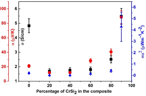
microparticles in various ratio followed by the uniaxial pressing under 100 MPa for 3 min. The σ , α and α2σ of the composite pellet as a function of percentage of CrSi
2 is represented in Fig.
8a. In the absence of the silicide, σ and α are 4.8 ± 0.5 S/cm and 21± 2 µV/K respectively. The Seebeck coefficient is given by the conducting PEDOT:PSS leading the charge transport. As the CrSi2 content increases, the σ does not vary much, but the Seebeck coefficient increases
with the silicide content up to 88 ± 9 µV/K; while the conductivity only reaches 5.4± 0.5 S/cm. Hence, in this composite it is clear that the power factor is improved significantly up to α2σ=
4 ± 1 µWm-1K-2 because of the Seebeck coefficient enhancement due to the presence of CrSi 2.
It is important to note that the composites exhibit isotropic behavior in their electrical conductivity and Seebeck coefficient values. The values of α obtained in the measurements carried out both parallel and perpendicular to the thickness of the composite pellet were not more than 4-5 % from each other. In addition, the perpendicular and parallel σ are of the same order of magnitude, further indicating the isotropy in the samples.The highest power factor is obtained for 90% CrSi2 composition. This indicates that it is important to get just the minimum
amount of conducting organic binder, likely because the electrical conductivity of the NFC-PEDOT:PSS compressed microparticles is lower than that of the pure CrSi2 microparticles.
But there is certainly a positive effect of the NFC-PEDOT:PSS binder on the conductivity. Fig. 8b shows the effect of DMSO treatment (Method 4) on the composite pellets. The micro-composite shows an overall increase in σ compared to the pristine situation, but the α was less (10-20 µV/K), thus indicating the domination of conducting polymer in the composite property. Hence this method was not used in the present case. In a coming study, we will investigate the
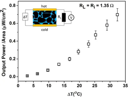
effect on the thermal conductivity. For the best composition, the pellet is then connected to a load resistance and submitted to a temperature gradient (Fig. 8c inset). The diameter of the pellet is 10 mm and thickness 2 mm. In order to obtain the maximum generated power, the load resistance is chosen to be equal to the resistance of the pellet (internal resistance Rint= RL =1.35
Ohms). It is important to note that the internal resistance mentioned includes the contact resistance and other electrical junctions that result in the voltage drop, adversely affecting maximum power transfer to the load. The power increases quadratically with ΔT up 32 οC and reaches 0.6 ± 0.1µW/cm2 as shown in Fig. 8c.
4. Conclusions
A room temperature method has been developed for the synthesis of a TE composite containing the microparticles of CrSi2 (inorganic filler) in an organic matrix of
NFC-PEDOT:PSS. Besides rendering stability to the composite structure, the NFC- PEDOT:PSS aerogel microparticles assist in electrical contact between the silicide microparticles, thus avoiding the use of complicated and expensive high temperature processing generally used in those materials. The latter is known to lead to a cost increase and a large CO2 fingerprint upon manufacturing TEG. The higest σ of 5.4 ± 0.5 S/cm and α of 88
± 9 µV/K has been measured for the composite with the correspoding α2σ of 4 ± 1 µWm-1K-2
at room temperature. At a tempearture difference of 32 οC, the output power /unit area drawn across the load with the resistance same as the internal resistance of the device is 0.6 ± 0.1 µW/cm2. Even though the power factor of the composite is low compared to its components,
it demonstartes a promising route for the low cost production of environmental friendly, bulk composites enabling the transition to a truly viable technology compatible with mass-manufacturing by printing for patterning legs on large area, and a subsequent low temperature/high pressure treatment for sintering the legs in the devices.
Acknowledgements:
The authors acknowledge the European Research Council (ERC-starting-grant 307596), the Knut and Alice Wallenberg foundation (project “Tail of the sun”), The Swedish Energy Agency, the Swedish Foundation for Strategic Research, and the Swedish Government Strategic Research Area in Materials Science on Functional Materials at Linköping University (Faculty Grant SFO-Mat-LiU No 2009 00971). The Innventia part of the work has been funded
by "the Power Papers project" - Knut and Alice Wallenberg foundation, and RISE - the Research Institutes of Sweden. Rajasekar Parasuraman acknowledges the University Grants Commission, India for his PhD fellowship.
References
[1] B. Poudel, Q. Hao, Y. Ma, Y. Lan, A. Minnich, B. Yu, X. Yan, D. Wang, A. Muto, D. Vashaee, X. Chen, J Liu, M. S. Dresselhaus, G. Chen, Z. Ren, High-thermoelectric performance of nanostructured bismuth antimony telluride bulk alloys, Science. 320 (2008) 634-638.
[2] G. J. Snyder, E. S. Toberer, Complex thermoelectric materials Nat. Mater. 7 (2008) 105 – 114.
[3] D. Madan, Z. Wang, A. Chen, R. Juang, J. Keist, P. K. Wright, J. W. Evans, Enhanced performance of dispenser printed MA n-type Bi2Te3 composite thermoelectric generators,
ACS Appl. Mater. Interfaces. 4 (2012) 6117–6124.
[4]H. Bottner, J. Nurnus, A. Schubert,D. M. Rowe, Thermoelectrics Handbook; Taylor and Francis: Boca Raton, FL, 2005; Chapter 46: Micro to Nano; pp 1−18.
[5] R .Venkatasubramanian, T. Colpitts, E. Watko, M. Lamvik, N. El-Masry, MOCVD of Bi2Te3, Sb2Te3 and their superlattice structures for thin-film thermoelectric applications, J.
Cryst. Growth 170 (1997) 817−821.
[6] H. Noro, K. Sato, H. Kagechika, The thermoelectric properties and crystallography of Bi-Sb-Te-Se thin films grown by ion beam sputtering, J. Appl. Phys. 73 (1993) 1252-1260. [7] Y. Hiroshige,M. Ookawa, N. Toshima, Thermoelectric figure-of-merit of iodine-doped copolymer of phenylenevinylene with dialkoxyphenylenevinylene, Synth. Met. 157 (2007) 467–474.
[8] O. Bubnova, Z. U. Khan, A. Malti, S. Braun, M. Fahlman, M. Berggren, X. Crispin, Optimization of the thermoelectric figure of merit in the conducting polymer poly(3,4-ethylenedioxythiophene), Nat. Mater. 10 (2011) 429-433.
[9] Y. Chen, Y. Zhao, Z. Liang, Solution processed organic thermoelectrics: towards flexible thermoelectric modules, Energy Environ. Sci. 8 (2015) 401-422.
[10] Q. Wei, M. Mukaida, K. Kirihara, Y. Naitoh, T. Ishida, Recent progress on PEDOT-based thermoelectric materials, Materials 8 (2015) 732-750.
[11] T. Park, C. Park, B. Kim, H. Shin, E. Kim, Flexible PEDOT electrodes with large thermoelectric power factors to generate electricity by the touch of fingertips, Energ. Environ. Sci. 6 (2013) 788-792.
[12] S. H. Lee, H. Park, S. Kim, W. Son, I. W. Cheong, J. H. Kim, Transparent and flexible organic semiconductor nanofilms with enhanced thermoelectric efficiency, J. Mater. Chem. A. 2 (2014) 7288-7294.
[13] G. H. Kim , L. Shao , K. Zhang , K. P. Pipe, Engineered doping of organic semiconductors for enhanced thermoelectric efficiency, Nat. Mater. 12(2013) 719-723.
[14] A. Weathers , Z. U. Khan , R. Brooke , D. Evans , M. T. Pettes , J. W. Andreasen , X. Crispin , L. Shi , Significant electronic thermal transport in the conducting polymer poly(3,4-ethylenedioxythiophene), Adv. Mater. 27 (2015) 2101-2106.
[15] S. Jeong, H. C. Song, W. W. Lee, Y. Choi, S. S. Lee, B-H. Ryu, Combined role of well-dispersed aqueous Ag ink and the molecular adhesive layer in inkjet printing the narrow and highly conductive Ag features on a glass substrate, J. Phys. Chem. C. 114 (2010), 22277-22283.
[16] A. Kamyshny, S. Magdassi, Conductive nanomaterials for printed electronics, Small. 10 (2014) 3515-3535.
[17] R. Funahashi, Y. Matsumura, T. Takeuchi, H. Tanaka, W. Norimatsu, E. Combe, R. O. Suzuki, C. Wan, Y. Wang, M. Kusunoki, K. Koumoto, New n-type silicide thermoelectric material with high oxidation resistance, Materials Research Society Symposium Proceedings. 1490 (2013) 103-112.
[18] S. Perumal , S. Gorsse, U. Ail, M. Prakasam, B. Chevalier, A. M. Umarji, Thermoelectric properties of chromium disilicide prepared by mechanical alloying, J Mater Sci 48 (2013) 6018–6024.
[19] N. Takao, I. Tanaka, H. Adachi, Chemical bonding of transition metal disilicides, Intermetallics, 4 (1996) S113-S118.
[20] L. Wågberg, G. Decher, M.Norgren, T. Lindström, M. Ankerfors, K. Axnäs, The build-up of polyelectrolyte multilayers of microfibrillated cellulose and cationic polyelectrolytes Langmuir. 24 (2008) 784–795.
[21]L. F. Mattheiss, Structural effects on the calculated semiconductor gap of CrSi2, Phys.
Rev B. 43 (1991) 1863-1866.
[22] D. Shinoda, S. Asanabe, Y. Sasaki, Semiconducting properties of chromium disilicide, J. Phys. Soc. Jpn. 19 (1964) 269-272.
[23] I. Nishida, The crystal growth and thermoelectric properties of chromium disilicide J. Mater. Sci 7 (1972) 1119–1124.
[24]M.I. Fedorov, Thermoelectric silicides: past, present and future, J. Thermoelectr. 2 (2009) 51-60.
[25] T. Dasgupta, A. M. Umarji, Role of milling parameters and impurity on the
thermoelectric properties of mechanically alloyed chromium silicide, J. Alloys. Compd. 461 (2008) 292-297.
[26] T. Dasgupta, J. Etourneau, B. Chevalier, S.F. Matar, A.M. Umarji, Structural, thermal, and electrical properties of CrSi2, J. Appl. Phys. 103 (2008) 113516 -1113516-7.
[27] S. Perumal, S. Gorsse, U. Ail, R. Decourt, A. M. Umarji, Effect of composition on thermoelectric properties of polycrystalline CrSi2, J. Electron. Mater. 42 (2013) 1042-1046.
[28] J. Liu, X. Wang, D. Li, N. E. Coates, R. A. Segalman, D. G. Cahill, Thermal conductivity and elastic constants of PEDOT:PSS with high electrical conductivity, Macromolecules. 48 (2015) 585–591.
[29] Y. Xia, J. Ouyang, Significant different conductivities of the two grades of poly(3,4-ethylenedioxythiophene):poly(styrenesulfonate), Clevios P and Clevios PH1000, arising from different molecular weights, ACS Appl. Mater. Interfaces. 4 (2012) 4131–4140.
[30] M. Henriksson, L. A. Berglund, P. Isaksson, T. Lindström, T. Nishino, Cellulose nanopaper structures of high toughness,Biomacromolecules, 9 (2008) 1579–1585.
[31] Z.U. Khan, J. Edberg, M. M.Hamedi, R.Gabrielsson, H.Granberg, L. Wågberg, I. Engquist, M. Berggren, X. Crispin, Thermoelectric polymers and their elastic aerogels, Adv. Mater. 28 (2016) 4556–4562.
[32] X. Crispin, F. L. E. Jakobsson, A. Crispin, P. C. M. Grim, P. Andersson, A. Volodin, C. van Haesendonck, M. Van der Auweraer, W. R. Salaneck, M. Berggren, The origin of the high conductivity of poly(3,4-ethylenedioxythiophene)−poly(styrenesulfonate)
(PEDOT−PSS) plastic electrodes, Chem. Mater. 18 (2006) 4354–4360.
[33]J. Y. Kim, J. H. Jung, D. E. Lee, J. Joo, Enhancement of electrical conductivity of poly(3,4-ethylenedioxythiophene)/poly(4-styrenesulfonate) by a change of solvents, Synth. Met. 126 (2002) 311-316.
Table 1: σ and α of the composite pellet synthesized via different methods.
Method System σ
(S/cm)
α (µV/K) Comments
1 CrSi2 PEDOT:PSS 1.5 ± 0.2 78 ± 8 Fragile
2 CrSi2 Freeze-dried PEDOT:PSS 1.2 ± 0.1 42 ± 4 Fragile 3 CrSi2 NFC microparticles 2.9 ± 0.3 105 ± 11 Strong pellet
Fig. 1: Thermoelectric generators with (a) a lateral architecture, and (b) a vertical architecture. (c) The vision of combining printing technology to fill cavities with thermoelectric composite and applying pressure at low temperature to sinter the legs.
(a)
(b)
Fig. 2: (a) Displays a thermoelectric leg with microparticles of CrSi2 (inorganic filler) in an
organic matrix of NFC-PEDOT:PSS, (b)The chemical structure of PEDOT:PSS, (c) crystal structure of CrSi2 [19]and (d) Chemical structure of NFC.
Cr Si
(b) PEDOT:PSS
(c) CrSi2
(d) NFC (a) TE leg
(a) (b)
Fig. 4: (a) Schematic representation of the synthesis procedure of NFC microparticles, (b) SEM of the NFC microparticles and (c) the corresponding image at high magnification, (d) SEM image of the NFC microparticles after the application of pressure (e) the corresponding image at high magnification.
(a)
(b) (c)
(a)
(b)
Fig. 5: (a) σ and α of the NFC-PEDOT:PSS under the DMSO treatments, (b) The schematic representation of the synthesis of the PEDOT:PSS incorporated in the NFC microparticles.
(a)
(b)
Fig. 6: (a) Schematic presentation of the possible origin of contact between the silicide microparticles via NFC-PEDOT:PSS microparticles and (b) the resistance versus load curve during the uniaxial preesing of the composites with PEDOT:PSS and without PEDOT:PSS in the NFC aerogel microparticles
(a)
(b)
Fig. 7: (a) SEM image of the micro-composite (b) High magnification SEM image reveals the hard inorganic CrSi2 particles an the soft organic NFC-PEDOT:PSS. (c) The EDX spectra of
to area: one taken on the hard particle and one on the soft matrix.
(a)
Fig. 8: (a) Evolution of the electrical conductivity σ, the Seebeck coefficient α, and the power factor σα2 for the the CrSi
2-NFC-PEDOT:PSS micro-composites upon varying the CrSi2
content. (b) Effect of DMSO treatment on the σ of the micro-composite pellet. (c) Power generated by the pellet submited to a temperature gradient (ΔT) for a load resistance of R=1.35Ω.
Supplementary Information
Room Temperature Synthesis of Transition Metal Silicide-Conducting
Polymer Micro-composites for Thermoelectric Applications
Ujwala Ail a, Zia Ullah Khan a, Hjalmar Granberg b, Fredrik Berthold b, Rajasekar Parasuraman
c, Arun M Umarji c, Kerstin Slettengren b, Henrik Pettersson b, Xavier Crispin a*
a. Department of Science and Technology, Linköpings Universitet, SE-60174 Norrköping, Sweden b. Innventia AB, Box 5604 , SE-114 86 Stockholm , Sweden
c. Materials Research Centre, Indian Institute of Science, Bangalore 560012, India
*E-mail: xavier.crispin@liu.se
Conductivity Measurements of the Composite Pellets
The sheet resistance RAB,CD of the composite pellets was calculated using Van der Pauw
geometry [1] (Fig.S1), by measuring the potential drop between the contacts D and C per unit current through the contacts A and B. Based on the similar definition, RBC, DA was calculated.
Fig S1: The van der Pauw geometry used for resistivity measurement of the composite pellets
Resistivity of the sample is given by the following expression,
ρ =𝑙𝑙𝑙𝑙2 �π𝑑𝑑 𝑅𝑅𝐴𝐴𝐴𝐴,𝐶𝐶𝐶𝐶+ 𝑅𝑅2 𝐴𝐴𝐶𝐶,𝐶𝐶𝐴𝐴� 𝑓𝑓 �𝑅𝑅𝑅𝑅𝐴𝐴𝐴𝐴,𝐶𝐶𝐶𝐶
Where, f is a function of the ratio RAB,CD / RBC, DA, that satisfies the following relation,
𝑅𝑅𝐴𝐴𝐴𝐴,𝐶𝐶𝐶𝐶− 𝑅𝑅𝐴𝐴𝐶𝐶,𝐶𝐶𝐴𝐴
𝑅𝑅𝐴𝐴𝐴𝐴,𝐶𝐶𝐶𝐶+ 𝑅𝑅𝐴𝐴𝐶𝐶,𝐶𝐶𝐴𝐴 = 𝑓𝑓 𝑎𝑎𝑎𝑎𝑎𝑎𝑎𝑎𝑎𝑎𝑎𝑎ℎ �
exp(𝑙𝑙𝑙𝑙2/𝑓𝑓) 2 �
Fig. S2: XRD of the CrSi2
Fig. S3: SEM of the pellets of NFC-PEDOT:PSS (left), NFC-PEDOT:PSS mixture treated with DMSO before pressing (middle) and NFC-PEDOT:PSS pellet treated with DMSO after pressing (right).
Determination of the Contact Resistance.
Contact resistance was calculated by measuring the two probe resistance of the composite pellet while pressing under different applied load pressure. It is important to note that there was no carbon paste used for this study, instead the contact was purely due to the mechanical force. Between the Ni-Fe metal die and the material. Fig. S4 shows the resistance of the pellet under various applied load mass for different thicknesses of the pellets. Note that in porous materials
submitted to high pressure has a strain-pressure relationship that is non-linear [2]. As a consequence, the evolution of the resistance versus thickness is non-linear as shown in Fig. S5. In first approximation, we used an exponential dependence of the resistance with thickness, from which the contact resistance was estimated by the intercept of the extrapolated curve on the resistance axis. Fig. S6 shows the estimated contact resistance as a function of load. Contact resistance varies exponentially with the applied load and the value reaches ~ 0.6 Ω at 100kg load.
Fig. S4: The resistance of the composite pellet as a function of applied load for different thickness.
Fig. S5: The resistance of the composite as a function of thickness for different applied load.
References
[1] L. J. van der Pauw, A method of measuring the resistivity and Hall coefficient of lamellae of arbitrary shape, Philips. Res. Rep. 13 (1958) 1-9.
[2] Gibson L. J. & Ashby M. F. Cellular solids: structure and properties, Pergamon, New York, 1988.
![Fig. 2: (a) Displays a thermoelectric leg with microparticles of CrSi 2 (inorganic filler) in an organic matrix of NFC-PEDOT:PSS, (b)The chemical structure of PEDOT:PSS, (c) crystal structure of CrSi 2 [19]and (d) Chemical structure of NFC](https://thumb-eu.123doks.com/thumbv2/5dokorg/5456681.141570/17.892.107.789.109.564/displays-thermoelectric-microparticles-inorganic-structure-structure-chemical-structure.webp)