IN THE FIELD OF TECHNOLOGY DEGREE PROJECT
MATERIALS DESIGN AND ENGINEERING AND THE MAIN FIELD OF STUDY
MECHANICAL ENGINEERING, SECOND CYCLE, 30 CREDITS
,
STOCKHOLM SWEDEN 2018
Innovative Methods for Welding
Ultra High Strength Steel with
Resistance Spot Welding
RICKARD ALDÉN
KTH ROYAL INSTITUTE OF TECHNOLOGY
Innovative Methods for Welding Ultra High Strength Steel with
Resistance Spot Welding
Abstract
Resistance spot welding (RSW) is the most frequently used method for welding thin sheets in manufacturing industries such as the automotive industry, because of the high productivity of RSW. In order to reduce CO2 emissions the automotive industry strives towards creating structures of light
weight, this is partly achieved by the use of lightweight materials such as Aluminum and composite materials. In parts of the car body designed to protect the driver and passengers in case of a collision High strength steel is used due to its high strength and relative high ductility. High strength steels are called Ultra High Strength Steels (UHSS) with typical ultimate tensile strength of 700 up to 2000 MPa and elongation of 10-40%. Because of the strive against lighter structures and great safety demands UHSS materials is of great interest for the automotive industry in order to create strong structures of light weight. In welding of modern materials such as UHSS with RSW, achieving adequate weld quality is a challenge. Hence this thesis aims to investigate new innovative ways to broaden the area of use and include modern materials such as UHSS for the traditional method of welding such as RSW. In RSW elliptical shaped welds are created between two or more faying metal sheets by passing current through the sheets. The current is applied to the sheets by copper electrodes in contact with the sheets on each side. The geometrical shape of these electrodes will affect multiple welding parameters such as applied stress, current density, electromagnetic stirring, temperature gradients and the possibility for the welded material to thermally expand during welding. Hence the
geometrical shape of the electrodes will affect the final shape and size of the weld nugget. In this thesis RSW electrode geometries are modified and tested. The weld properties from modified electrodes are compared to the weld properties from standard RSW electrodes with respect to process robustness, weld nugget shape and size, micro hardness and weld tensile strength. Various modified geometries are used, all modified geometries are designed in order to allow the welded material to expand more, compared to standard electrodes. Previous work has been done and shown that hollow electrodes that allow the welded material to expand can improve the weld quality and process robustness. However, this has been to the cost of nugget growth in the normal direction to the welded sheet, leaving a non-uniform surface. Hence the aim of this thesis is to investigate if it is possible to widen the current range in the weld lobe diagram when welding UHSS material
combinations with RSW by the use of hollow electrodes without affecting weld quality negatively compared to standard electrodes. Weld quality in this thesis will be evaluated based on surface condition, mechanical strength, micro-hardness and weld nugget size. The modified electrodes have shown better weld properties with respect of current range in the weld lobe curves in most cases tested but not all of the material combinations tested compared with standard electrodes. The surface conditions of the welded specimens have been controlled by measuring any indent and raise by line laser scanning. Modified RSW electrodes has showed improved welding properties with respect to current range in the weld lobe curves compared to standard RSW electrodes when welding UHSS material combinations. However modified electrodes have shown a higher sensitivity to misalignment and angle fault. Several material combinations of UHSS that has shown non-weldable behavior with standard RSW electrodes have shown improved current range. In the best case the current range was increased to 3,9 kA for an UHSS material combination that is non-weldable with standard electrodes.
Sammanfattning
Motståndsvetsning är den vanligaste metoden för svetsning av tunna plåtar i tillverkningsindustrier som bilindustrin på grund av den höga produktiviteten hos punktsvetsning. För att minska
koldioxidutsläppen strävar bilindustrin efter att skapa lättviktskonstruktioner, vilket delvis uppnås genom användning av lätta material såsom aluminium och kompositmaterial. I delar av bilkroppen konstruerad för att skydda föraren och passagerare vid kollision används höghållfast stål på grund av sin höga hållfasthet och relativt höga duktilitet. Höghållfasta stål kallas Ultra High Strength Steels (UHSS) med typisk draghållfasthet på 700 upp till 2000 MPa och förlängning av 10-40%. På grund av bilindustrins strävan mot lättare strukturer och höga säkerhetskrav är UHSS-material av stort intresse för bilindustrin för att skapa starka strukturer av lätt vikt. Vid svetsning av moderna material som UHSS med punktsvetsning är det en utmaning att uppnå tillräcklig svetskvalitet. Därför syftar denna avhandling till att undersöka nya innovativa sätt att bredda användningsområdet och inkludera moderna material som UHSS för den traditionella svetsmetoden punktsvetsning. Under
punktsvetsning skapas elliptiskt formade svetsar mellan två eller flera metallplåtar genom att ström passerar genom plåtarna. Strömmen appliceras till plåtarna genom kopparelektroder i kontakt med plåtarna på var sida. Den geometriska formen av dessa elektroder kommer att påverka flera svetsegenskaper såsom applicerad tryck, strömtäthet, elektromagnetisk omröring,
temperaturgradienter och möjligheten för det svetsade materialet att termiskt expandera under svetsning. Följaktligen kommer den geometriska formen av elektroderna att påverka den slutliga formen och storleken hos svetslinsen. I denna avhandling modifieras och testas elektrodgeometrier som används vid punktsvetsning. Svetsegenskaperna från modifierade elektroder jämförs med svetsegenskaperna från standardelektroder med avseende på processens robusthet, svetslinsform-och storlek, mikrohårdhet svetslinsform-och svetshållfasthet. Olika modifierade geometrier används, alla
modifierade geometrier är utformade för att låta det svetsade materialet expandera mer jämfört med standardelektroder. Tidigare arbete har gjorts och visat att ihåliga elektroder som tillåter det svetsade materialet att expandera kan förbättra svetskvaliteten och processens robusthet. Detta har dock varit till kostnaden av svetslinstillväxt i riktning vinkelrätt till den svetsade plåten, vilket lämnar en ojämn yta. Avsikten med denna avhandling är därför att undersöka om det är möjligt att bredda användingen av punktsvetsning till svetsning av UHSS-materialkombinationer genom användning av ihåliga elektroder utan att påverka svetskvaliteten negativt jämfört med standardelektroder. Svetskvaliteten i denna avhandling kommer att utvärderas baserat på yttillstånd, mekanisk hållfasthet, mikrohårdhet och svetslinsstorlek. De modifierade elektroderna har visat bättre svetsegenskaper med avseende på svetsbarhet i de flesta fall testade men inte alla
materialkombinationer som testats jämfört med standardelektroder. Ytförhållandena för de svetsade exemplen har kontrollerats genom att mäta intryck och upphöjnad på den svetsade ytan genom laserskanning. Flera materialkombinationer av UHSS som har visat sig osvetsbara med standard elektroder har visat förbättrad svetsbarhet med modifierade elektroder. I bästa fall ökade
strömintervallet med godkänd svets till 3,9 kA för en UHSS-materialkombination som inte är svetsbar med standardelektroder.
Table of contents
1. INTRODUCTION... 1
2. HYPOTHESIS ... 2
3. BACKGROUND ... 2
3.1 RESISTANCE SPOT WELDING ... 2
3.1.1 Joules laws of heating ... 2
3.1.2 Bulk resistance, contact resistance and dynamic resistance ... 3
3.1.3 RSW parameters ... 5
3.1.3.1 Weld current ... 5
3.1.3.2 Weld time ... 6
3.1.3.3 Electrode force ... 6
3.1.3.4 RSW cycle ... 6
3.1.4 Weld lobe curves ... 6
3.1.4.1 Nugget size ... 7
3.1.4.2 Expulsion ... 7
3.1.4.3 1D Weld lobe curves ... 7
3.1.4.4 2D Weld lobe curves ... 8
3.1.5 Shuntning effect ... 8 3.1.6 Electrodes ... 9 3.1.6.1 Electrode materials... 9 3.1.6.2 Electrode geometries ... 9 3.1.6.3 Dressing of electrodes ... 10 3.1.6.4 Hollow electrodes ... 11 3.2 LIMITATIONS ... 13 3.2.1 Weld quality ... 13 3.2.2 Peltier Effect ... 13
3.2.3 Misalignment & Angle fault ... 13
4. EXPERIMENTAL ... 16
4.1 MATERIAL ... 16
4.2 MODIFIED ELECTRODES ... 17
4.3 METHOD ... 20
4.3.1 Manufacturing and Dressing of electrodes ... 20
4.3.2 Welding equipment ... 20 4.3.3 Metrological equipment ... 20 4.3.3.1 Electrode measurements ... 20 4.3.3.2 Surface measurements ... 21 4.3.3.3 Nugget measurement ... 21 4.3.4 Chisel test ... 22
4.3.5 Sample preparation and cross sections ... 22
4.3.6 Hardness test ... 22
4.3.7 Mechanical testing ... 23
5. RESULTS & DISCUSSION ... 24
5.1 WELD LOBE AND SURFACE CONDITION ... 24
5.2 LOM&HARDNESS ... 32
5.3 ELECTRODE MEASUREMENTS ... 34
6. CONCLUSIONS ... 37
7. FUTURE WORK ... 37
8. ACKNOWLEDGEMENT ... 38
9. REFERENCES ... 39
10. APPENDIX ... 41
10.1 WELD LOBE DIAGRAMS ... 41
1
1. Introduction
Resistance spot welding (RSW) is a widely used method of joining for manufacturing industries since its invention in 1886 by Elihu Thomson (Houldcroft, et al., JULY/AUGUST 1986). RSW produces small elliptical weld nuggets between two or more faying metal sheets, generally 2-6 mm in diameter. This is executed in a relatively short time of roughly 250 ms. The short weld time makes RSW a welding method with high productivity. Because of the high productivity it has been exceptionally popular in the automotive industry historically. In a typical car body there are 2000-5000 welds executed by RSW
(Pouranvari, et al., 2007). Historically
conventional mild steels with strengths up to 400 MPa are used for the car body. For such mild steels it is a well-known fact that it is relatively easy to achieve required weld quality through RSW in mild steel materials. However, since fuel consumption of cars is dependent on the weight, the automotive industry strives towards using lighter materials. Material requirement present in automotive industry due to risk of collision makes steel of high strength and relative high ductility of interest in parts of the car where deformation should be held under a specific limit in case of collision. The highest demand for low deformation in case of collision is found in the safety cage of the car designed to protect the passengers. Steels are
continuously being developed by the steel manufacturers and novel steels of higher strengths have become more popular to use in the car body where deformation is to be kept under the acceptable amount to meet safety requirement in the case of a collision. These steels are named Ultra High Strength Steels (UHSS). UHSS show better properties relative to mild steels to be used in applications where high strength has importance while
maintaining ductility matters also. The use of
different materials in the car body of the new Volvo V60 announced in 2018 is illustrated in Figure 1. An exact amount of UHSS in the new Volvo V60 is not officially available. But in previous model of the Volvo XC 90 released in 2014 the percentage of UHSS used in the whole car body weight was 40%.
Figure 1 New Volvo V60 announced in 2018, materials
used in car body and safety cage. (Volvo Car Group,
2018)
It is relatively problematic to achieve desirable weld result in UHSS through RSW (Larsson, et al., 2009), due to the widely different physical properties in UHSS. One common problem is caused by presence of surface coatings. Another challenge comes up when welding UHSS to traditional steels with dissimilar physical properties. Previous work has been conducted to show that a hollow electrode will allow an increased thermal expansion of the welded material and hence widen the current range in the weld lobe curves, in 2 sheet setup of Zn-coated mild steel (Yeom, et al., 2009) and 3 sheet setup of dissimilar steels (Donghyun, et al., 2016). However, this improvement in current range has been at the cost of nugget growth in the direction normal to the welded sheet. This nugget growth in direction normal to the welded sheet has resulted in a non-uniform surface. This indent and rise in the surface of the welded specimen is not desirable in many cases when the surface is subject to subsequent treatments, such as painting, or when the surface of the
2 welded sheet will be visible in the final
product.
2. Hypothesis
The goal of this thesis is to investigate
innovative ways of improving the RSW process so that adequate weld quality can be achieved with modern steels such as UHSS. Weld quality in this thesis is evaluated based on current range in weld lobe diagram, surface conditions, solid mechanical properties, micro-hardness. These four aspects of weld quality will be investigated and compared to results obtained from welding with standard electrodes. Adequate weld quality will be defined as when the welding result from welding trials with modified electrodes are on par or better compared to standard electrodes in each of the weld quality sub categories. Hence the hypothesis of this thesis is that there is an electrode geometry that allows welding of UHSS material combinations through RSW with adequate weld quality, by allowing the welded material to expand in to the electrodes in the direction normal to the sheet welded. This hypothesis will be confirmed or rejected by investigating research questions as listed below.
1. Is it possible to replicate results from previous work. To widen the current range in the weld lobe diagram by the use of hollow electrode, without affecting solid mechanical properties negatively compared to standard electrodes?
2. Is it possible to widen the current range in the weld lobe diagram when welding UHSS material combinations with RSW by the use of hollow electrodes. Without affecting weld quality negatively compared to standard electrodes?
3. Background
In order to successfully improve the weld result through modification of the electrode geometries, a fundamental understanding of the RSW process is required. Hence this part of the reports aims to give a basic
understanding in the RSW process, electrode geometries and its influence on weld results.
3.1 Resistance Spot Welding
The explanation of RSW in this thesis is divided in to physical heating; bulk resistance, contact resistance and dynamic resistance; RSW parameters; Weld lobe curves; Shunting effect.3.1.1 Joules laws of heating In resistance spot welding (RSW) the weld nugget is achieved through Joules laws of heating also called Joule heating, which states that in any conductor the heat generated by current flow is directly proportional to the time of current flow and the square of the current (Crew, 1921). This is shown in (1) where Q is thermal energy [J], I is electrical current [A], R is electrical resistance [Ω] and t is time [s] of current flow.
𝑸 = 𝑰𝟐𝑹𝒕 (1)
If the weld current and resistance is variable Joule heating can be described by integrating (1) in respect to the time, this is shown in (2) where Q is thermal energy [J], I is electrical current [A], R is electrical resistance [Ω] and t is time [s] of current flow.
𝑄(𝑡) = ∫ 𝐼𝑡 2(𝑡)𝑅(𝑡)𝑑𝑡
0 (2)
In RSW the effect of Joule heating is utilized by passing a current through the stack of
3 materials intended for welding, this is
illustrated in Figure 2. Two copper electrodes apply pressure to each side of the material stack and current is passed through the material. The generated heat is proportional to the electrical resistance as described earlier in (1). Since the resistance of the copper electrodes is considerably lower than in the steel sheets, the weld nugget will form in between these sheets where the electrical resistance is highest. The copper electrodes are also water cooled which further prevent melting of the electrode and substrate contact area.
Figure 2 Schematic of the RSW process (Kimchi &
Phillips, 2018).
3.1.2 Bulk resistance, contact resistance and dynamic resistance
A schematic illustration of relative electrical resistance for the RSW setup is show in Figure 3 . Here starting from the top and 1, we have relatively low electrical resistance in the bulk material of the copper electrodes, as copper has significantly lower electrical resistance compared to steel even at elevated temperatures. In 2 a slight increase in
electrical resistance due to contact resistance between the electrode and substrate surfaces, contact resistance is further explain later in this thesis. 3 is the bulk resistance of the steel substrate. 4 has the highest electrical
resistance due to the contact resistance of the steel sheets, hence this is where first melting and weld nugget formation will occur. Then 5, 6 and 7 have similar properties as 3, 2 and 1 respectively due to symmetry.
Figure 3 Relative resistance in the RSW setup. (Kimchi &
Phillips, 2018)
This schematic is at least true for the initial RSW setup. Two factors will affect the relative electrical resistance during the RSW process. Firstly melting of the substrate will cause the contact resistance between the sheets to be eliminated. Secondly the bulk resistance of the material will increase rapidly due to the temperature dependence of the materials resistivity. This can be understood from (3) and Figure 4.
In equation (3) R is electrical resistance [Ω], 𝜌 is resistivity [Ωm], L is length of conductor [m] and A is area of conductor [m2].
𝐑 = 𝛒𝐋
𝑨 (3)
The temperature dependence of resistivity illustrated in Figure 4 will cause an increase in bulk resistance with increasing temperature as
R ∝ ρ from (3). The increased resistance at
increased temperature will cause more heat to be generated as Q ∝ R from (1). The temperature dependence of the bulk materials resistivity is the cause of the rapid nature of RSW.
4
Figure 4 Temperature dependence of resistivity for Steel
and Copper. (Kimchi & Phillips, 2018)
Contact resistance heavily affects the RSW process as mentioned earlier. The amount of contact resistance is mainly a function of the electrode force, material surface conditions and the presence of oxides or coatings on the material surface. For example, the surface of aluminum is naturally covered in aluminum oxide (Al2O3) which acts as an insulator and
hence need to be removed before RSW can be executed. This is usually done by chemical or electrical cleaning of the surfaces, or by the use of RSW copper electrodes which is specially designed for breaking the Al2O3 prior
to welding. In the case of UHSS materials the presence of surface coatings often need to be taken in to consideration before welding with RSW. These coatings are designed as corrosion protection and as an oxidation inhibitor during the manufacturing of the steel sheets. These coatings usually consist of zinc (Zn) or an aluminum silicon (AlSi) mixture. The Zn coating is applied through galvanization or submerging of the steel sheets in molten Zn. AlSi coatings are applied through submerging in melt solely.
The materials bulk resistance can be
considered as independent of pressure (Zhang & Senkara, 2006), while contact resistance is a function of the electrode force applied from
the RSW electrodes on the steel sheets. A larger electrode force will deform surface asperities and allow for a larger contact area, hence a larger electrode force will cause reduction in contact resistance. This is illustrated in Figure 5 .
Figure 5 The effect of electrode force on contact
resistance (Kimchi & Phillips, 2018).
Considering Figure 5 it suggests that the electrode force should be chosen as low as possible to allow for a high contact resistance and a faster heat generation. While this is true, in practice this approach will cause problems. As the steel sheets are not
processed to exact tolerances and have small deviations in surface roughness. Deviations in sheet thickness and sheet offset would result in large errors of the contact resistance, and in extension affect the weld nugget size which is heavily related to the welds mechanical properties (Zhang, et al., 2011). Another problem when using low electrode force would be the built-in inexactness of the equipment supplying the electrode force, as low deviations in electrode force will cause large deviations in contact resistance at a low electrode force. The contact resistance dependence of applied electrode force is shown in Figure 6. Considering Figure 6 it is clear that a small deviation in electrode force at low electrode forces will produce a larger error in contact resistance relative to a small deviation in electrode force at high electrode forces.
5
Figure 6 The contact resistance dependence of electrode
force (Kimchi & Phillips, 2018).
As bulk resistance is temperature dependent and contact resistance is dependent of electrode force, a more generic term is used to explain the total resistance in an RSW setup. This is called dynamic resistance and aims to give understanding of how bulk resistance and contact resistance changes over the period of the RSW weld cycle. An illustration of the dynamic resistance is shown in Figure 7. Here at the beginning there is a relatively high dynamic resistance due to the high contact resistance between the steel sheets. As the surface starts to soften and break down when the current is applied the dynamic resistance is decreasing due to the increased contact area between the steel sheets. The contact resistance continues to decrease but at one point the rapidly
increasing bulk resistance caused by increase in temperature starts to dominate, the dynamic resistance increases as a result. Now rapid heating occurs as the heat generated is proportional to the resistance and the resistance is heavily temperature dependent. Shortly after first melting the dynamic resistance start to decrease again, this is due to the fact that the molten nugget between the steel sheets is now growing and providing the current to pass through a larger area and thereby lowering the current density and resistance. Indention of the copper electrodes
does cause a shorter path for the current to pass through the material, this also results in a decrease in resistance as shown in (3). Finally, there is a rapid decrease in dynamic resistance, this is due to expulsion. Expulsion is when the molten nugget grows too big or when the hydrostatic pressure of the molten nugget caused by material expansion during heating and melting exceeds the pressure applied by the electrodes, so that liquid metal is rapidly pushed out between the steel sheets. Expulsion is further explained later in this thesis, as it is a non-desirable effect and a considerable quality risk for RSW. Expulsion is a defect which is generally a larger problem in UHSS and when welding dissimilar or coated materials, as the current range of the weld lobe curve often is smaller and currents used often is close to the expulsion limit.
Figure 7 Change in dynamic resistance during an RSW
cycle (DICKINSON, et al., 1980).
3.1.3 RSW parameters
The main RSW parameters consist of weld current, weld time and electrode force. The main RSW parameters will be explained briefly in following chapters.
3.1.3.1 Weld current Weld current is the parameter most
commonly altered in order to influence weld result in RSW, as the heat generation is proportional to the square of the applied current as shown in (1). Here a too low weld current will result in a too small nugget or no
6 bonding at all, a too large weld current will
result in expulsion. Expulsion causes most of the molten metal to evacuate the intended weld area, resulting in a weaker weld as well as potential damage on surrounding parts and equipment. Typical weld currents used in RSW when welding steel are 5-10 [kA] (Andersson, 2013).
3.1.3.2 Weld time
In (1) we can see that the time elapsed during current flow affect heat generation and thus also weld results. However as the number of spot welds in one car body is in the order of thousands, weld time is usually kept to a minimum in order to keep production cycle times down. Typical weld times for RSW are 200-500 [ms] (Andersson, 2013).
3.1.3.3 Electrode force
Electrode force is a necessary parameter of RSW in order to handle potential geometrical variation in the material stack and to ensure a closed current loop. However as discussed earlier, excessive electrode force lowers the contact resistance and heat generation in the early stages of the RSW process, resulting in proponed nugget formation and increased weld time. It has been shown that overloading the electrode force reduces nugget size and mechanical properties of the weld
(Pouranvari, et al., 2007). Typical electrode forces used in RSW are 3-6 [kN] (Andersson, 2013).
3.1.3.4 RSW cycle
An RSW cycle utilizes the parameters previously described and always contains steps of squeeze time, weld time and hold time. Squeeze time is the time it takes for the RSW equipment to reach desirable electrode force in order to hold the welded material in place during welding. Hold time is the time after weld current is applied but before force is released. The purpose of hold time is to allow for the water-cooled electrodes to
transport heat from the welded sheet. In some cases hold time includes a temper time or temper current. Temper current is a current which is smaller in magnitude compared to welding current and the purpose of the temper current is to lower the cooling rate of the welded nugget. Temper current can be used in situations when martensitic
transformation due to high cooling rate should be avoided. RSW cycles are often complex, especially in the case of RSW of UHSS
materials. When welding UHSS the weld cycles are built up by pulsing the weld current in order to melt and remove surface oxides and coatings if present in a first current pulse, then subsequent weld pulses is designed to allow the weld nugget to grow to desirable size between the metal sheets. The aim of this method is to have a clean contact area
between the metal sheets for the second weld pulse to achieve a weld nugget, as would be the case for non-coated steels. A schematic over the RSW cycle is shown in Figure 8.
Figure 8 RSW weld cycle. (Kimchi & Phillips, 2018)
3.1.4 Weld lobe curves
In order to determine the weld cycle results, the most common method used is weld lobe diagrams. Basically a weld lobe diagram shows how much the weld current can vary while maintaining an adequate weld nugget size. The lower quality limit for weld nugget size is determined as a function of sheet thickness t [m] and can be expressed as 4√𝑡 [m]. Usually t is determined from the thickness of the thickest outer sheets in a stack-up. The lower
7 limit of weld nugget size will vary in different industries and applications. The upper quality limit for weld nugget size is when expulsion occurs. Weld lobe curves is further explained in sections 3.1.4.3 and 3.1.4.4.
3.1.4.1 Nugget size
To measure the weld nugget formed between the metal sheets, the metal sheets are forced apart by a chisel and hydraulic press. The weld plug diameter is then determined through measuring over the nuggets largest diameter and perpendicular to its largest diameter, the total nugget diameter is defined as the mean of these two measurements. The measured nuggets can look different for different
materials and welding parameters. A summary of the most usual fracture cases when chisel testing spot welds are shown in Figure 9.
Figure 9 Different fracture modes when destructive
testing of RSW welds. (Kimchi & Phillips, 2018)
In RSW of UHSS the most common fracture mode is button pull, also called full button pull. In the case of too low welding current or welding time UHSS show the no fusion fracture mode, also called interfacial fracture. Interfacial fracture is considered to have no nugget, even though the metal sheets are bonded interfacialy and have some mechanical strength.
3.1.4.2 Expulsion
Expulsion is the event that occurs when the hydrostatic pressure of the molten nugget becomes greater than the clamping force applied by the electrodes. Molten metal is rapidly pushed out of the fusion zone and to the surrounding area. This can be caused by too high welding time and welding current or insufficient electrode force. Instabilities in the process such as misalignments of the
equipment and material stack may also cause expulsion. A simplified analysis of the force balance is presented by (Zhang & Senkara, 2006) and illustrated in Figure 10. In Figure 10 FE, applied is the squeezing force applied by the
electrodes, FN is the force from the molten
nugget generated by pressure P acting on the solid base material, Fx is the compressive force
acting on the faying surfaces and thus constraining the molten nugget. In this simplified model of expulsion occurs when FN>FX.
Figure 10 The force balance of the molten nugget and
electrodes in RSW.
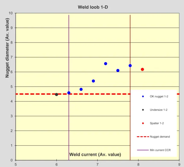
3.1.4.3 1D Weld lobe curves One dimensional lobe curves, also called current range curves, is an experimental way of determining the robustness of an RSW setup. One out of three welding parameters is varied whilst the other two are kept constant, the result is collected as the size of the weld nugget. Usually weld current is varied while
8 electrode force and weld time is kept
constant, since weld current is the most prominent RSW parameter given in (1). In the case of varying current, the 1D lobe diagram tells us during which span of current adequate weld nugget size can be achieved before expulsion occurs. An example of a 1D lobe diagram is shown in Figure 11.
Figure 11 1D lobe diagram. (Kimchi & Phillips, 2018)
3.1.4.4 2D Weld lobe curves 2D weld lobe curves is constructed from multiple 1D lobe curves, where one 1D lobe curve corresponds to two points in a 2D lobe curve. In the 2D lobe curve the axis consist of two out of the RSW parameters; weld current, weld time and electrode force. The way 2D lobe curves are constructed from 1D lobe curves is illustrated in Figure 12. 2D lobe curves provide a process window for which parameter values acceptable nuggets are produced.
Figure 12 How 2D lobe curves are constructed. (Kimchi
& Phillips, 2018)
3.1.5 Shuntning effect
When RSW is used in manufacturing industries the material is generally joined in multiple locations called weld spots. This will allow for a small portion of the weld current to leak from the intended welding area through previously welded spots. This phenomenon is called the shunting effect, the amount of current leakage is dependent on the distance between the welded spots and the welded materials electrical conductivity. The shunting effect is illustrated in Figure 13.
9 Because of the shunting effect weld spots
should be placed with a certain distance from each other in order to avoid large current leakage due to the shunting effect. Optimum distance between welded spots will vary from different materials and will not be
investigated in this thesis. However a standardized so-called shunt weld will be placed at a controlled distance from all the investigated welds in this thesis, this is to imitate the environment present in the manufacturing industries. The dimensions of the welded specimens in this thesis are shown in Figure 14 , including location of the shunt weld, marked with green. The investigated weld is marked with red.
Figure 14 Dimensions of welded specimens used in this
thesis. Test spot marked in red and shunt spot marked in green.
3.1.6 Electrodes
Electrodes have multiple properties that need to be taken in to consideration when choosing an electrode for RSW. The electrode material need to be strong enough to clamp the material intended to weld and have higher electrical and thermal conductivity than the material welded. Often electrodes are chosen from the strength of the base material, as when electrodes start to wear the area of the electrodes in contact with the base material is increasing due to so called mushrooming. This will lead to a lower current density and smaller weld nuggets. Choosing electrode is often a tradeoff between strength and electrical/thermal conductivity. As when strength is increased thermal and electrical
conductivity is decreased (Kimchi & Phillips, 2018).
3.1.6.1 Electrode materials The electrodes used in this thesis are of type CuCr1Zr from manufacturer Luvata. The basic material properties are shown in Table 1.
Table 1 Material properties of electrodes. (Luvata Pori
Oy, 2018)
Property Value Unit
Density 8890 [kg/m3] Specific Heat Capacity 385 [J/(kg*K)] Electrical Conductivity 78 [% IACS*] Thermal Conductivity 320 [W/(m*K)] Thermal Expansion Coefficient 17,6 [10-6/K]
* % IACS = International Annealed Copper Standard. The
% IACS values are calculated as percentages of the standard value for annealed high conductivity copper as
laid down by the International Electrotechnical Commission.
Chemical composition of CuCr1Zr electrodes from Luavata is shown in Table 2.
Table 2 Chemical composition of electrode material.
(Luvata Pori Oy, 2018)
Element [wt. %]
Cr 0,5-1,0
Zr 0,05-0,15
Cu bal.
3.1.6.2 Electrode geometries It is clear from previous work that the
geometry of electrodes used in RSW influence current density, cooling rate and applied stress. Hence the geometry of the electrode also influences formation and final shape of the nugget (Chan, et al., 2006), (Li, et al., 2013). In RSW there is a wide array of standard electrode geometries available, which each may have suitable properties depending on the intended application. Some
10 examples of standard electrode geometries
used in RSW are shown in Figure 15.
Figure 15 Examples of electrode geometries. (SIS-
Swedish Standards Institute, 1981)
In this thesis exclusively electrodes with geometries of Type B is used, geometry showed in Figure 16 and measurements are shown in Table 3.
Figure 16 Geometry of electrode Type B used in this
thesis. (SIS- Swedish Standards Institute, 1981) In this thesis electrodes of sizes d1 = 16 [mm]
& d1 = 20 [mm] are used. Full measurements
are shown in Table 3. The standard electrodes are often referred to by the type and diameter
d1 and d2 of the electrode. The larger outer
diameter d1 also referred to just outer
diameter and the smaller diameter d2 is
referred to as flank diameter. The standard
electrodes in this thesis will be referred to as 16/6 and 20/8 from the measurements of d1
and d2 given in Table 3. As all electrodes in this
thesis are of type B all electrodes will be referred to by their measurements and the type will not be mentioned further.
Table 3 Shows measurements of electrodes used in this
thesis. (SIS- Swedish Standards Institute, 1981)
d1 [mm] d2 [mm] R1 [mm]
16 6 40
20 8 50
An image of the standard electrodes used in this thesis is shown in Figure 17.
Figure 17 Standard electrodes Type B. Size 20/8 [mm]
and 16/6 [mm].
3.1.6.3 Dressing of electrodes During RSW the electrodes deform over time due to the exposure to mechanical stress at elevated temperatures. This deformation is highly dependent on the type of material welded since material with greater mechanical strength which will require a greater electrode force to be constrained during welding. Coatings on the welded material can affect the deformation process. For example Zn based material coatings is known to negatively affect the RSW process as the Zn has a relatively low melting temperature the Zn based coating will soften during welding and stick to the
electrode surface resulting in inferior electrical conductivity in the electrode for subsequent welds. Diffusion of base material in to the electrodes can result in softening of the electrode tip which will accelerate the
11 deformation and decrease the electrical
conductivity of the electrode. In order to remove contamination from the electrode tip and ensure the intended geometrical shape of the electrode a double sided rotating cutting tool is used while the electrodes are mounted in the RSW equipment. An example of the schematics of an RSW Dressing tool is shown in Figure 18 .
Figure 18 Schematic of RSW electrode Dressing tool.
(Wesltd, 2018)
The rotating cutting tool is placed between the electrodes mounted in the RSW equipment and the RSW equipment apply force to the electrodes. No current is applied to the electrodes while dressing the
electrodes. Generally the electrode force used while dressing is lower than the electrode force during welding. Besides the obvious benefits of dressing the electrodes by removing contamination and ensuring geometrical shape, the Dressing tool can also decrease some of the effects of errors such as misalignment. Misalignments of the
electrodes can to some extent be eliminated by dressing electrodes internally since the dressing is performed when the electrodes are mounted in the weld gun so that the surface processed by the rotating dressing tool will be parallel to the material intended to weld subsequent to electrode dressing.
3.1.6.4 Hollow electrodes
Previous work has been performed to modify the geometry of the RSW electrode in order to allow for better weld results in terms of current range in 1D weld lobe curves
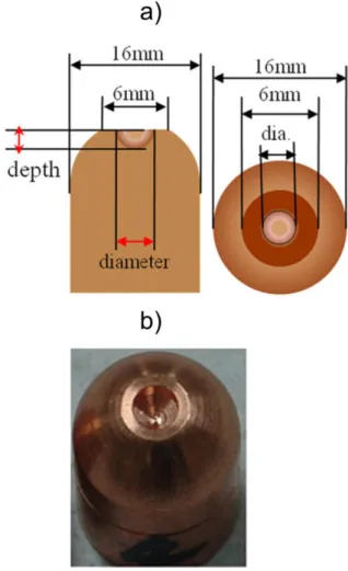
(Donghyun, et al., 2016), (Jun & Rhee, 2012), (Yeom, et al., 2009). The method used in these reports of modifying the geometry has proven to be effective in improving the current range of the 1D weld lobe curves. In three cases an electrode shape that allows for the molten nugget to expand in to cavities of the electrode has been used. An example of hollow electrode geometry used in (Jun & Rhee, 2012) is shown in Figure 19. Values from (Jun & Rhee, 2012), not presented in Figure 19, are depth of 3 mm and dimeter of 4 mm.
Figure 19 a) Dimensions of modified electrode used. b)
Image of modified electrode. Both from (Jun & Rhee,
12 In (Yeom, et al., 2009) no upper limit in the
weld lobe curve was found even though the weld current was increased well above the expulsion limit for standard electrodes. Worth noting is that the minimum current to achieve minimum required weld nugget diameter does also increase with the modified electrodes in (Yeom, et al., 2009). In Figure 20 results from mechanical testing preformed in (Jun & Rhee, 2012) of a two sheet SPRC440 material combination is shown. Sheet thickness used in (Jun & Rhee, 2012) was 1 mm. It can be seen from Figure 20 that it is possible to achieve weld nuggets as strong, or in some cases stronger, with modified electrode compared to standard electrode. Worth noting about Figure 20 is that in the case of standard electrode; in Figure 19 a) the current steps used is close to the expulsion limit and there by no current step of greater magnitude can be used while in Figure 19 b) for the case of modified electrode no upper current limit for expulsion could be found. The lack of
expulsion limit when welding with modified electrodes in (Jun & Rhee, 2012) means it is possible that available current steps of larger magnitude could give even greater mechanical strengths when testing tensile shear strength and cross tension strength.
Figure 20 Tensile shear strength (TSS) and Cross tensile
strength (CTS) for a) standard electrode and b) for modified electrode. (Jun & Rhee, 2012)
However, it has shown to be of the cost of profound indentation and raise of the visible surface in welded area, leaving a non-uniform surface which can be deemed as a defect in the case that the welded surface will be visible to the final costumer. An example of surface raise when using modified electrodes in previous work is shown in Figure 21 (Donghyun, et al., 2016). In Figure 21 a modified electrode has been used in combination with a conventional standard electrode. The modified electrode on the bottom side and standard electrode on the top side in Figure 21.
Figure 21 Example of surface raise from use of modified
13 In this thesis the same mechanism of
improved welding results will be utilized but with the ambition to improve the geometry of the electrodes cavity and hence the surface properties of the final welded specimen, so that the indentation and/or raise of the surface area of the weld is minimized.
3.2 Limitations
Some aspects of RSW have deliberately been left out of this thesis in order to maintain a reasonable scope of the thesis and an
effective resource management. The aspect of RSW which are left out are as follows.
3.2.1 Weld quality
Aspects of weld quality that will not be investigated in this thesis are listed in this section. These aspects of weld quality will not be investigated in this thesis since the test methods of these properties are time consuming and costly. These properties are deemed as not highly relevant in this early stage of investigation. However these properties of weld quality are important to consider if these modified electrodes will be introduced to production of applications subject to dynamic loads, corrosive environments and surface properties in applications subject to painting or other surface treatments subsequent to welding. Dynamic mechanical strength, corrosion resistance, surface condition are all properties that will not be investigated in thesis. Surface conditions will partly be observed in this thesis while welding with modified electrodes. However the surface conditions effect on subsequent treatments such as painting will not be investigated.
3.2.2 Peltier Effect
Peltier effect can be described as when the electrons pass through material of different fermi levels the electrons change orbits. The
Peltier effect is dependent of the direction of the current, the direction of the current will determine if energy is released or absorbed. The Peltier effect is described by (4) where Qp is heat generated by the Peltier effect [J], I is current [A], t is time [s], ПA and ΠB are Peltier coefficients which are material dependent.
𝑄𝑝(t) = ∫ 𝐼(𝑡)(𝑡
0
Π𝐴− Π𝐵)𝑑𝑡 (4)
The heat generated from Peltier effect is generally one order of magnitude smaller compared to the heat generated by the Joule effect (Löveborn, 2016). Hence in order to simplify the investigation in this thesis the Peltier effect will not be considered.
3.2.3 Misalignment & Angle fault Misalignment is a well-known source of error in RSW and can affect the robustness of the RSW setup heavily. Misalignment occurs when the two center lines of the upper and lower electrode are not completely aligned and, this is shown in Figure 22 . Misalignment may cause a faster nugget formation at a given electrode force and weld time compared to
14 perfectly aligned electrodes.
Figure 22 Misalignment with distance d between
electrode center lines.
The faster nugget formation during misalignment is caused by the increased current density due to the decreased contact area. Even though misalignment may cause a faster nugget formation it is the cause of a less robust RSW process as misalignment causes expulsion at an earlier stage when compared to perfectly aligned electrodes. Previous work has been preformed (WEN, et al., 2009) where different misalignment distances d were tested and dynamic resistance recorded. It was found that expulsion occurred with increased misalignment distance d as shown in Figure 23 (WEN, et al., 2009). Hence misalignment is considered an error which is to be minimized in order to secure weld
quality and robustness of the RSW process.
Figure 23 The effect of axial misalignment on dynamic
resistance. (WEN, et al., 2009)
Problem with decreased RSW process
robustness due to misalignment is thought to be a greater problem when welding with modified electrodes compared to standard electrodes. The reason that the misalignment error is thought to be a greater problem when welding with modified electrodes is that in order to create cavities in the modified
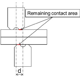
electrodes, contact area is inevitably removed. The decreased contact area of the modified electrodes will cause even greater current density in the case of misalignment compared to standard electrodes. The increase in current density will cause the welded nugget to form faster and possibly expulsion to occur earlier. The remaining contact area of the modified electrodes in the RSW setup with misalignment distance d is shown in side view in Figure 24 and in top view in Figure 25.
15
Figure 24 Remaining contact area when welding with
modified electrodes during misalignment.
As the contact area of the modified electrodes is non-uniform during misalignment as shown in Figure 25 misalignment may cause a non-uniform weld nugget. It should be noted that the misalignment illustrated in Figure 24 and Figure 25 are schematic illustrations and not by any means measured values of
misalignment distance d.
Figure 25 Top view of remaining contact area of
modified electrodes during misalignment. Top electrode marked green and bottom electrode in red.
Angle fault is when the two center lines of the electrodes are not parallel. Angle fault may occur from multiple reasons such as flex in the RSW equipment, bent or crooked parts in the RSW equipment, poor fitting of the electrode
to the RSW equipment. Angle fault can occur in one of the two electrodes separately or in both electrodes simultaneously. An example of angle fault in the upper electrode is shown in Figure 26.
Figure 26 Example of angle fault by angle α in the upper
electrode.
In this thesis an additional potential source of angle fault is introduced during the
manufacturing of the modified electrodes. The potential source of angle fault while
manufacturing the modified electrodes occurs when the surface used for manufacturing and the surface used for welding is not parallel. The surfaces involved include the outer cylindrical surface that is gripped in order to suspend the electrode in the lathe and the inner conical surface of the electrode that is subsequently used when fitting the modified electrode in the RSW equipment. If the outer surface that is gripped in the lathe and the inner surface that is used for fitting the modified electrode in the RSW equipment are not parallel it will cause one or both of the
16 modified electrodes to apply the electrode
force with an angle to the sheet. Hence angle fault can cause non-uniformity in indentation, current density, stress distribution and weld nugget. The misalignment distance d will not be measured or attempted to control in this thesis as misalignment may occur from multiple reasons that are difficult to
accurately control. However it is important to be aware of the effect of misalignment when evaluating RSW results and especially when preforming welds with electrodes of reduced contact area such as the modified electrodes investigated in this thesis. The negative effect of misalignment can to some degree be avoided by the use of a Dressing tool as described earlier in 3.1.6.3. As the Dressing tool is used when the electrodes is mounted in the RSW equipment if misalignment is present some of the negative effect of the
misalignment can be eliminated due shaping of the electrode in the misaligned position. In this thesis the modified electrodes is produced in a lathe and it is possible that the suspended position of the electrode in the lathe differs slightly from the position in the RSW equipment. This possible small variation in positioning of the electrode would usually not be a problem for standard electrodes as Dressing tools are used after the electrodes are mounted in the RSW equipment to ensure the final shape and position of the electrode and contact area. However development and manufacturing of Dressing cutting tools in a time consuming and expensive procedure and will not be included for the modified
electrodes investigated in this thesis.
4. Experimental
In the following chapters the material and methods used in this thesis will be explained. However no chapter of methodology or discussion about methods used will be included.
4.1 Material
Materials used in welding experiments are USIBOR1500P, DP600 and Zn-coated boron steel. The USIBOR1500P was included in multiple variations in this thesis and will forth be named by USIBOR followed by thickness and potential heat treatment. The thickness of the USIBOR steel varied with 1,1mm, 1,2mm, 1,4mm and 1,8mm. The heat treatment of the USIBOR is either not mentioned in the case of three sheet material combinations as the heat treatment of the USIBOR plates in three sheet material combinations are according to standard temperature and dwell time. The heat treatment of USIBOR sheets named 900s dwell time aims to simulate deviations in the manufacturing of the USIBOR sheets with prolonged dwell time. The USIBOR sheets with normal dwell time will be referred to at USIBOR 192s which refers to the normal dwell time of the USIBOR sheets. The chemical compositions of the materials are shown in Table 4. The material coating type and
thickness are shown in Table 5. Some material composition and coating data are absent. This is because of that the material suppliers do not want to share the specifications of the material. In the case of the Zn-coated boron steel the only information provided to the author is that the material is of similar character as the USIBOR1500P, and has a Zn-based coating. The Zn-coated boron steel has been sand blasted subsequent to coating application. The sand blasting treatment has given the material a smooth surface. The effect on physical properties and purpose of the sand blasting treatment is unknown to the author but is still mentioned here as it may affect the weldability. The DP600 material is also of unknown composition to the author as the supplier does not wish to share that information. The only information available to the author about the material is that it is of dual phase nature and of ultimate tensile strength of roughly 600 MPa.
17
Table 4 Chemical composition of materials used for
welding experiments. Material Usib o r1 50 0 P DP6 00 Zn -c o ated bo ro n s tee l C *0,25 Si *0,4 Mn *1,4 P S Al Ti Nb B *0,005 Cr Mo Cu
All materials used in this thesis had kind of surface coating. The coatings are designed for corrosion protection or to assist in the
manufacturing of the metal sheets. The coatings have no purpose in welding of the metal sheets. Surface coating type and composition is shown in Table 5.
Table 5 Surface coating type and composition of
materials used for experiments.
Kolumn1 Coati n g t yp e C o ati n g mass [ g/ m 2 ] C o ati n g t h ic kn e ss [ μ m ] Usibor1500P AS75/75 150 DP600 GI50/50 100 7
Zn-coated boron steel Zn
4.2 Modified Electrodes
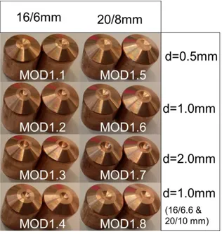
The modified electrodes were manufactured in two iterations MOD1 and MOD2. MOD1 was manufactured in ten variants were all had a spherical cavity in the center of theelectrode contact area. The depth of the cavity was varied in three steps of 0.5, 1.0 and 2.0 mm0mm. Images of electrodes from MOD1 series are shown in Figure 27 .
Figure 27 Electrodes from MOD1 series.
When creating the cavities in the modified electrodes contact area is inevitably removed from the electrodes. The decreased contact area due to material removal when creating the cavities in the modified electrodes is expected to affect the current density and the applied stress to the welded material. In order to be able to investigate the influence of increased current density and applied stress a kind of hybrid electrodes was produced. The hybrid electrodes share the larger diameter of the standard electrodes of 16- and 20mm, but the smaller flank diameter of 6 and 8mm was increased so that after the hybrid electrodes had been modified with a cavity in the center of the contact area the total remaining contact area was equal to that of a standard electrode of same size. These hybrid
18 electrodes are referred to as size of 16/6.6and 20/10. Measurements of electrodes in MOD1 is shown in Table 6. The wider contact area of MOD1.4 and MOD1.8 is shown in Figure 27. After welding trials with electrodes from MOD1 had been performed the electrodes in MOD2 was created. In MOD2 the results from welding trials in MOD1 was taken in
consideration. The results from welding trials in MOD1 will be discussed later in this thesis, but the geometries of the different variants in MOD2 will be explained below. The electrodes in MOD2 were created in four different geometries and will be referred to as MOD2.5, MOD2.6, MOD2.7 and MOD2.8. In the first variant of MOD2 referred to as MOD2.5 a kind of S-shape was utilized. The thought behind this S-shape was that the raise in the middle of the electrode would contribute with heat transfer from the center of the surface of the welded specimens to the water-cooled electrode. As well as reducing the current density from the edges of the weld. In
MOD2.5 the shape of the cavity that allows for the welded material to expand is of a torus rather that of the spherical shape used in MOD1. The truncated angle of 30° and flank diameter of 8mm in MOD2.5 was kept in order to not change outer dimensions of the electrode. The purpose of the preserved outer measurements of the electrode is to make the modified electrodes more compatible with standardized production equipment and construction methods used today. In the case of MOD2.6 the flank angle of 30° was kept but the flank diameter was widened. The widened flank diameter was created in order to
investigate if the increased contact area from the increase in flank diameter would
contribute to weld quality. The cavity created in MOD2.6 was of spherical shape and of substantially larger volume compared to the other variants in MOD2. The thought behind the geometry of MOD2.6 was to see if
increased contract area and a large volume of
the cavity in the electrode could improve the weld quality. As mentioned earlier it is preferred to keep the flank angle of 30° and flank diameter of 8mm if possible due to compatibility with production units used today by the industries. However the geometrical shape of MOD2.6 could be of interest if it would prove to be able to achieve desirable weld quality where other electrodes cannot. MOD2.7 and MOD2.8 is of similar geometry with a rounded contact area of same shape in both cases. The difference between MOD2.7 and MOD2.8 is the geometrical shape and volume of the cavity designed to allow the welded material to expand. In the case of MOD2.7 the cavity is of the shape of an exponential cone and in the case of MOD2.8 the cavity is of spherical shape. It is of interest to investigate if the larger volume of the cavity in the case of MOD2.7 relative to MOD2.8 can improve the weld quality. It is deemed a considerable risk for material sticking from the welded material to the electrode with the sharp geometry in MOD 2.7. Schematic views of electrodes in MOD2 series is shown in Figure 28 and in Figure 30. Closer view of the contact area of the electrodes in MOD2 series are shown in Figure 29.
19
Figure 28 Schematic view of MOD2 series.
Figure 29 close view of the contact area of the
electrodes in MOD2 series.
Figure 30 Summarized view of modified electrodes in
MOD2 series.
Table 6 Specifications of electrodes in MOD1.
Name: size: [mm] d: [mm] t: [mm] r: [mm] MOD1.1 16/6 0.5 1.0 4.2 MOD1.2 16/6 1.0 1.0 2.4 MOD1.3 16/6 2.0 1.0 1.9 MOD1.4 16/6,6 1.0 1.6 2.4 MOD1.4.2 16/6.6 0.5 1.6 4.2 MOD1.5 20/8 0.5 1.0 9.2 MOD1.6 20/8 1.0 1.0 4.9 MOD1.7 20/8 2.0 1.0 3.2 MOD1.8 20/10 1.0 2.0 4.9 MOD1.8.2 20/10 0.5 2.0 9.2
20
4.3 Method
Methods used in this thesis aimed to modify standard electrodes used in RSW of type B and evaluate the weld quality compared to
standard electrodes. Manufacturing and measuring methods used are described in following sub chapters.
4.3.1 Manufacturing and Dressing of electrodes
The modified electrodes were manufactured in a CNC lathe of according to the geometries specified in previous chapter. The standard electrodes were dressed by a rotating pneumatic cutting tool while mounted in the RSW equipment. In some cases modified electrodes were dressed by rotating cutting tool with a cutting tool intended to dress standard electrodes. The purpose and results of dressing modified electrodes is shown and discussed in 5.1.
4.3.2 Welding equipment
The RSW equipment used in this thesis is from manufacturer Matuschek. Welding equipment specifications is shown in Table 7. Welding parameters used by the welding equipment varied with materials and electrodes used and will be specified with each welding result. In all cases a double weld pulse was utilized. The purpose of the pre-pulse in the double weld pulse setup is to remove surface coating present as described earlier in 3.1.3.4.
Table 7 Welding equipment properties and data.
Equipment property Equipment data
MaxElectrode force:
[kN] (daN) 8
Short circuit current:
[kA] 38
Current type: [AC,
MFDC] MFDC
Water cooling per
electrode: [l/min] 4
Weld control unit:
PC-based Matuschek Servo Studio Transformer: Expert 222kVA(4diod) 50 turn ratio Inverter: Matuschek Servo SPATZ M800LL Welding gun:
Matuschek Servo gun C-type 4.3.3 Metrological equipment Different metrological tools have been used to measure the welded nugget and inspect surface conditions. The different metrological tools used included surface probe, line laser scanner and Vernier caliper. The different metrological equipment used is further explained in following sub chapters.
4.3.3.1 Electrode measurements In some cases the manufactured electrodes were control measured with surface probe. This was to control geometrical conditions after manufacturing in lathe as the electrodes normally is not manufactured in a lathe. Welding test was done with standard
electrode of different manufacturing methods in order to see the influence of the surface condition of the electrodes on the nugget growth and weld lobe diagram. The weld test consisted of standard electrodes
manufactured and formatted in the traditional way by dressing the electrode in the RSW equipment. The other set of standard electrodes was formatted in a lathe to the same dimensions. The surface conditions were
21 compared before the weld test. Measured
values of interest from the surface probe test are surface roughness and the geometrical radius of the contact area of the electrode as given by Figure 16 and Table 3. After welding with the measured standard electrodes weld lobe diagrams was created. The weld lobe diagrams was then compared in order to see the influence of surface processing method on the weld lobe diagram. As no apparent major affect from the surface condition on the electrodes from the two different dressing processed was observed the results from surface probe measurements will not be included in 5.1 but will be included in 10.
4.3.3.2 Surface measurements The surface conditions of welded specimens were measured with line laser scanner. The line laser measurements of the surface were done in order to understand how different electrode geometries would affect the surface at different welding currents. The
measurement data obtained from line laser measurements was then plotted on a secondary axis in the weld lobe diagram. The purpose of plotting data from line laser measurements in the weld lobe diagram is to illustrate how the surface conditions will vary with varying weld current. When profiling the surface condition from line laser
measurement the profile was characterized in three measurements. These three
measurements was defined as Indent, Raise and Standard Indent (STD Indent). Indent is the mean value of the indent caused by the modified electrode measured from the material surface to the lowest point in the indent by four points of measurement. Raise is the highest point of the welded material surface caused by the expansion of the welded material in to the modified electrode. Raise is presented as mean value from two measurements. STD Indent is the mean value
of the indent caused by the standard
electrode measured from the material surface to the lowest point in the indent by two points of measurement.
Figure 31 Schematic view of line laser measurements.
Since most material combinations in this thesis are non-weldable a comparison with weld results from standard electrodes is impossible. Instead of comparing indentation with standard electrodes a general maximum indentation limit is set to of 20% of the total thickness of the material stack. As raise in welded surface does not occur when welding with standard electrodes it will solely be observed how great the raise is and how it varies with weld current.
4.3.3.3 Nugget measurement
Welded specimens were destructively tested and measured. The destructive testing method will be described in 4.3.4. The weld plug was measured with a Mitutoyo Vernier caliper.
22
Figure 32 Measurements d1 and d2 of weld plug
measured by Vernier caliper.
Weld plug diameter is defined as the mean value of d1 and d2 where d1 is the greatest
value of the weld plug diameter and d2 is
measured perpendicular to d1.
4.3.4 Chisel test
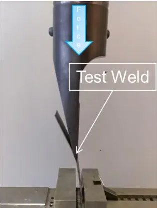
The weld lobe diagrams were constructed from measurements from destructive chisel tests. Tool used for chisel test was a hydraulic press equipped with a chisel, shown in Figure 33 . The two sheets are forced apart by the chisel and the weld plug is pulled out of one of the sheets and leaves a cavity. The weld plug is then measured from the sheet where the plug is attached. In the case of three sheet combinations the procedure is repeated and the weld plug diameter is measured for each interface.
Figure 33 Chisel test of two sheet material combination.
4.3.5 Sample preparation and cross sections
Samples for cross section analysis include cross sections for light optical macroscope and micro hardness analysis trough Vickers
hardness measurements. All samples were cut with a rotation abrasive disc and subsequently molded in Stuers conductive plaster. The molded specimens were hand polished in multiple steps on sand paper of decreasing roughness in steps of p300, p420, P600, p1200, p2500, p4000. The specimens was polished by hand on polishing cloth with diamond suspension of decreasing roughness of 6 μm, 3 μm, 1 μm and 0,25 μm subsequent to polishing by sandpaper. Samples for light optical macroscope evaluation were etched in a Nital 5% solution for 30s.
4.3.6 Hardness test
In order to determine if the modified
electrodes influence the micro hardness of the fusion zone (FZ) and heat affected zone(HAZ) compared with standard electrodes a 2D
23 Vickers micro hardness mapping was
performed. The equipment was of
manufacturer Qness. In the Vickers hardness 2D mapping a two-dimensional point grid was created over the cross section of the welded area. The Vickers equipment then make an indent of the surface and measure the
diameter of the indent automatically and from the measured value calculate the hardness value of the area in HV1.
4.3.7 Mechanical testing
Welded specimens were tested for mechanical strength by shear tensile test and cross tensile test. The schematic of shear tensile test specimens was performed in two interactions and is shown in Figure 34 and Figure 35. The first iteration of shear tensile tests was non-successful in fracturing the weld in the specimens. Instead in the first iteration of shear tensile test as shown in Figure 34 the specimen was fractured in the base material in the relatively weak DP600 middle sheet. In order to evaluate the mechanical strength of the weld nugget performed by modified electrodes compared with standard electrodes it is necessary for the tested specimen to fracture in the welded area. Hence the results from tensile shear test iteration 1 will not be used for comparison with standard electrodes in this thesis. However the results from tensile shear test iteration 1 will be included in this thesis as it might be of interest for future work in the area.
Figure 34 Schematic of tensile shear test setup iteration
1.
Because of the unwanted fracture mode for cross tension test specimens are shown in Figure 36, a second iteration of tensile tests was designed and designed and the schematic
of tensile test in iteration 2 is shown in Figure 35 and Figure 36. The schematic in Figure 35 and Figure 36 includes three sheet material combinations. In the case of two sheet material combinations the same setup was used but without the middle sheet and only the two outer sheets was welded and tensile strength is tested.
Figure 35 Schematic of tensile shear test setup iteration
2.
The specimens were constrained and pulled at a rate of 10 [mm/min] until fracture occurred. Data recorded during tensile testing includes applied force [kN] and displacement [mm].
Figure 36 Schematic of three sheet cross tension test
24
5. Results & Discussion
The results from modification iteration MOD1 and MOD2 will be presented separately in each sub category as follows. The result sub categories will be divided to weld lobe and surface, geometric measurements of electrodes, cross section analysis and mechanical testing.
5.1 Weld lobe and surface
condition
Weld lobe diagrams was created in this thesis and most of them will be presented in the appendix section rather than in the results section as it is the authors belief that readers are interested in the value of the current range from the weld lobe diagrams rather than the whole diagram. However in case it would be of interest for future work the weld lobe diagrams will be presented in 10. In order to provide a more holistic view of the weld results in terms of current range a summarizing view will be provided in Figure 48, Figure 49 and Figure 50. However a novel type of weld lobe diagrams was created in this thesis. The weld lobe diagrams were created in order to provide a comprehensible
overview of the weld lobe combined with the surface condition of the welded specimen. Therefore a weld lobe diagram with a secondary axis was created. In the combined weld lobe and surface condition diagram the main axis is identical to a conventional weld lobe diagram with nugget diameter [mm] plotted on the vertical axis and weld current [kA] plotted on the horizontal axis. In the combined weld lobe and surface condition diagram a secondary vertical axis was added where indentation and raise were plotted [mm]. The secondary axis of the combined weld lobe and surface condition diagram was created so that origin of the secondary axis is coinciding with the minimum nugget demand that is plotted as a dashed horizontal line from
the main horizontal axis. The coinciding of origin on the secondary axis and the dashed horizontal line of the main axis representing minimum nugget demand enables the reader to interpret the dashed horizontal line of the diagram as both minimum nugget demand from the weld nugget measurements as well as the surface of the material welded from the line laser measurements creating a more holistic view of the weld result obtained. In Figure 37 and Figure 38 combined weld lobe and surface condition diagrams of Zn-coated boron steel is presented. In the case of Zn-coated boron steel no acceptable weld nugget could be achieved with standard electrodes so each current step with approved weld nugget diameter with modified electrodes is an improvement compared to standard electrodes. The surface conditions of the welded specimen are represented in Figure 37 as indent and raise. The measuring point of indent and raise is defined earlier in Figure 31. From Figure 37 it can be seen that a current range of 0.6 kA with a largest indent of 0.06mm or 2.5% of the material stack thickness and a largest raise of 0.4mm or 16.7% of the material stack thickness.
Figure 37 Combined weld lobe and surface condition
diagram. For electrode MOD1.4.2, modified against modified electrode and Zn coated boron steel.
In Figure 38 an identical setup to that in Figure 37 is presented with the exception that in