Mälardalen University Press Licentiate Theses No. 152
TOWARDS A GUIDELINE FOR
REFACTORING OF EMBEDDED SYSTEMS
Sara Dersten 2012
Copyright © Sara Dersten, 2012 ISBN 978-91-7485-070-3
ISSN 1651-9256
Abstract
The electronics in automotive systems give great possibilities. It has contrib-uted to environmental improvements through reduced emissions and reduced fuel consumption, safety, driver assistance, and quality through better diag-nostic capabilities.
Automotive systems are today distributed embedded systems that consist of several nodes that communicate with each other. The increasing possibili-ties have led to a situation where functions that used to be stand-alone, are today dependent on several inter-connected systems which all contribute to the desired functionality. This has increased the costs and the complexity to deal with the systems.
The automotive industry is adopting a new open software architecture, called AUTOSAR, that is intended to reduce the complexity. AUTOSAR also gives possibilities for coping with large product ranges and for compo-nent sharing. The introduction of AUTOSAR is an example of an architec-ture change without modifying the external functionality. We have chosen to call such changes system refactoring.
However, if the introduction of AUTOSAR is not successfully performed, there are risks for delayed development projects, which are costly for the automotive companies. Unfortunately, existing engineering standards and literature focus mostly on new product development and less on system re-factoring, and this gap needs to be filled. The goal of this research is to pro-vide guidelines for refactoring, which propro-vides support throughout the com-plete process of system architects in efforts to refactor the system.
This thesis identifies the characteristics of refactoring processes. This is done by empirical studies of the drivers behind refactoring, the effects we can expect from refactoring, and the process activities and characteristics. The result can be used to create guidelines for improving the work of refac-toring.
Acknowledgements
Starting doctoral studies was a type of life refactoring. To successfully per-form this task, I needed support. There are several persons that have contrib-uted to this support, consciously or unconsciously.
My supervisor, Jakob Axelsson, has supported me during the entire pro-cess. He helped me structuring my research work and finding relevant ques-tions and, still, he always let me chose my own ways. My co-supervisor, Joakim Fröberg, helped me get started, both with practicalities and with the study plans. For a short time, I had the privilege to have Rikard Land, as a second co-supervisor, who was a co-author of my first and best written pa-per. I have at Volvo CE the pleasure to work with Nils-Erik Bånkestad. He has during my research studies, especially in the last part, supported me with interesting ideas for research. The rest of my colleagues, at the E/E system architecture department, have been very understanding when my focus has been on my studies instead of current department issues. Several persons at the research community have been significant for me. It was Christer Nor-ström that convinced me to start the doctoral studies. Before I accepted, I consulted Johan Kraft to find out more. I had many laughs with my former roommates, Rafia Inam and Saad Mubeen. Later I got the opportunity to share room with Stefan Cedergren, Peter Wallin, Håkan Gustavsson, Anton Jansen, Anders Wall, and Stig Larsson, who all gave me more insight into the business aspects of electronics. Daniel Sundmark gave me valuable comments on my thesis proposal. I learned a lot when assisting Gordana Dodig-Crnkovic, Jan Gustafsson and Daniel Flemström in courses. All prac-tical problems were smoothly solved by Monica Wasell and Carola Rytters-son. In fact, all doctoral students and personnel at Mälardalen University are very nice. Unfortunately, there is limited space to mention everyone, since I want this section to fit in one page.
My dear friends, Jasmin and Isabell, have been very understanding when I have been occupied writing papers or travelling to conferences.
My family, has shown great patience and made lots of sacrifices, so I fi-nally could complete this task, especially my nearest and dearest, Christian and Ylva.
List of Papers
This thesis is based on the following papers.
Paper A Dersten, S., Fröberg, J., Axelsson, J., Land, R. (2010) Analy-sis of the Business Effects of Software Architecture Refactor-ing in an Automotive Development Organization. Proceed-ings of the 36th EUROMICRO Conference on Software Engi-neering and Advanced Applications (SEAA) 2010, 269–278 Paper B Dersten, S., Axelsson, J., Fröberg, J. (2011) Effect Analysis
of the Introduction of AUTOSAR. A Systematic Literature Review. Proceedings of the 37th EUROMICRO Conference on Software Engineering and Advanced Applications (SEAA) 2011, 239–246
Paper C Dersten, S., Axelsson, J., Fröberg, J. (2012) An empirical study of refactoring decisions in embedded software and sys-tems. Proceedings of the Conference on Systems Engineering Research (CSER) 2012, 8: 279–284
Paper D Dersten, S., Axelsson, J., Fröberg, J. (2012) Characteristics of a System Refactoring Process in Embedded Systems Devel-opment. Submitted to the 7th Workshop on SHAring and Re-using architectural Knowledge (SHARK) 2012
Contents
1. Introduction ... 1
1.1 Complexity in automotive systems ... 2
1.2 Automotive development ... 2 1.3 System architecture ... 4 1.4 Thesis outline ... 6 2. Research scope ... 7 2.1 Problem formulation ... 7 2.2 Research questions ... 9 2.3 Research method ... 9 3. Results ... 19
3.1 Which effects can be expected from a system refactoring? ... 19
3.2 What are the drivers of system refactoring decisions? ... 25
3.3 What would a guideline need to contain to support system refactoring?... 28
3.4 Discussion ... 33
4. Related work ... 41
4.1 Drivers of refactoring ... 41
4.2 Effects from refactoring ... 42
4.3 The system architecture process and the role of the architect ... 45
4.4 Decision-making ... 46 5. Conclusion ... 51 5.1 Contribution ... 51 5.2 Future work ... 52 References ... 53 Paper A ... 59 Paper B ... 79 Paper C ... 99 Paper D ... 107
Abbreviations
ABS
Antilock brake system
AHP
Analytic hierarchy process
ALMA
Architecture level modifiability analysis
ATAM
Architecture trade-off analysis method
AUTOSAR
Automotive open system architecture
AYC
Active yaw control
CBAM
Cost benefit analysis method
COTS
Commercial off the shelf
EBD
Electronic brake force distribution
ECU
Electronic control unit
EMC
Electromagnetic compatibility
ESC
Electronic stability control
ESP
Electronic stability program
OEM
Original equipment manufacturer
ROI
Return on investment
SAAM
Software analysis architecture method
SW-C
Software component
TCS
Traction control system
1.
Introduction
Automotive systems are large distributed systems that consist of several inter-connected electronic control units. In automotive systems the com-plexity has increased to a level where it becomes very hard to adapt to new technologies in order to fulfill new customer, environmental and legal re-quirements. One reason is that the electronics system constitutes a more im-portant part of the functionality and the business around it. The functions that before were managed by stand-alone systems, are today dependent on several inter-connected systems which all contribute to the desired function-ality. Therefore, a system architecture, i.e. a structure for the system and its components, is needed to ensure that desired requirements are met.
Lately there have been several major recalls of vehicles from different au-tomotive producers [1-3]. The increasing complexity of the auau-tomotive elec-tronic systems is blamed for those incidents. To deal with the problem manu-facturers and automotive suppliers together developed an open standardized architecture for automotive systems. The result is a common software archi-tecture for automotive systems called AUTOSAR. The automotive industry hopes that AUTOSAR will reduce this complexity.
Companies world-wide are now introducing AUTOSAR into their prod-ucts. This means that the architecture is changed, without any changes in product functionality that is visible to the user. We have chosen to call such changes system refactoring.
However, introducing AUTOSAR may not be as easy as the companies think. It will give effects, not only in the electronics systems, but also across the company organization. Production systems have to be adjusted; the de-velopment environment needs to be updated; and processes and responsibili-ties have to be developed. If these factors are not set in time, the develop-ment projects that are going to use the new software architecture may be delayed.
A missed deadline is very costly and the automotive companies want to avoid this. Therefore, there is a need for the companies to prepare them-selves in time before the introduction of AUTOSAR. Current practices and the processes described in the systems engineering standards are mostly con-centrating on new product development and less on system refactoring. We think there is a gap here that needs to be filled. Therefore we aim to provide guidelines for system refactoring to be used in the architecture process. The
goal of the research behind this licentiate thesis is to acquire the required knowledge for constructing these guidelines.
1.1
Complexity in automotive systems
The complexity in automotive systems can be demonstrated by the Electron-ic Stability Control (ESC), also referred to as ElectronElectron-ic Stability Program (ESP). It improves safety by recognizing unstable driving conditions and taking appropriate actions. To prevent over-steering and under-steering, braking is applied to the vehicle wheels. ESC is common in all types of ve-hicles, including cars, trucks and busses [4, 5]. ESC relies on several other vehicle systems: Antilock Brake System (ABS), a safety system which pre-vents the wheels from locking up; Electronic Brake force Distribution (EBD), a system that varies the braking force applied on each wheel; Trac-tion Control System (TCS), a system which regulates the power supplied to the wheels; and Active Yaw Control (AYC), a system that uses an active differential to transfer torque to the wheels that have the best grip on the road. Traditionally each of these systems consists of at least one electronic control unit (ECU) which together with connected sensors and actuators handles system functionality. Nowadays, modern systems must be able to cooperate across different domains. These interconnections add dependen-cies in the system, like temporal dependendependen-cies or state dependendependen-cies of con-trol units [6].
1.2
Automotive development
The development of automotive systems usually uses a product-line ap-proach and component-based development. Introducing these methodologies in a traditional system includes refactoring since the system has to be adjust-ed to fit a new component model or product platform. For that reason, we have based our research and literature studies on the introduction of these development approaches. We will here give a brief background to them.
1.2.1 Component-based development
In component based development software systems are built from existing components. This means that components can be reused and shared between product releases and product variants. The advantages are reductions of time-to-market, development cost and maintenance cost [7, 8]. Since a re-used component is already re-used and tested in different contexts, there might also be a possibility that the component is more reliable than a newly
devel-can be developed in-house, bought from an external subsystem developer or as off-the-shelf components (COTS).
1.2.2 Component-based development in automotive systems
using AUTOSAR
AUTOSAR (AUTomotive Open System Architecture) [9] is a component-based model for automotive systems. It provides a common software infra-structure for automotive systems based on standardized interfaces and com-ponents. Key features are modularity, configurability, standardized interfac-es and a runtime environment. A layered software platform facilitatinterfac-es the achievement of the technical goals modularity, scalability, transferability and reusability of components. Automotive manufacturers and suppliers hope that AUTOSAR will help managing complexity.
In the AUTOSAR architecture, each ECU incorporates a basic software component which includes infrastructural services such as operating system functionality, vehicle network communication, memory services, diagnostics and ECU state management. The basic software component is built as a lay-ered structure where each layer is abstracted from the lower layers and hence independent of hardware implementations. The application layer is located on top of the basic software. An application is built up by one or several AUTOSAR software components (SW-Cs) that are located on one ECU or distributed on several ECUs. The AUTOSAR SW-C contains parts of the application functionality and is atomic, meaning that it only can be located on one ECU. The AUTOSAR SW-Cs can also be responsible for handling of specific sensors or actuators.
The AUTOSAR SW-Cs are communicating through the Virtual function-al bus (VFB), a middleware responsible for mapping of communication mes-sages. Usually the address and source information in the communication messages are specified by the sending application component. In the AU-TOSAR methodology the address and source information of all communica-tion messages are configured in system development. During run-time this information is mapped to each message by the VFB. This methodology re-quires specific development tools to help OEMs (Original Equipment Manu-facturers), and suppliers to design and map SW-Cs, ECUs, networks, sensors and actuators.
1.2.3 Product-line development
Another example of a typical system refactoring is the introduction of prod-uct-lines. The idea with product-lines is to reuse the same basis, a platform, in several members of a product family. The platform methodology is nor-mally structured as layers, as components or as a combination of these. On
top of this platform each specific product adds its own core functionality or features. In this way, one can concentrate on specific properties of each product member instead of inventing the same things over and over again. One example is construction equipment. Both an articulated hauler and a wheel loader need power management and communication between elec-tronic control units. However, they differ a lot in core functionality. The wheel loader needs to have complicated control for lifting its arms when the articulated hauler might have advanced suspension systems.
The reason why product-lines are so beneficial are not only due to re-use of software code [7]. Product-line approaches save time during the require-ment phase since almost all requirerequire-ments can be reused between products and releases. Also many architectural problems are already solved and the system architects can concentrate on core functionality. Other aspects such as project planning might also be easier when less functionality has to be developed in each project. One important factor for a successful utilization of a product-line approach is variability management [10]. However, there might be several issues related to the introduction [11]. The use of product-line architecture requires increased knowledge by the engineers. Other prob-lems are conflicting quality requirements of components in different context or in different products.
1.3
System architecture
Refactoring of the system and its infrastructure involves selection of tech-nology solutions and leads to compromises between desired, but conflicting, characteristics; activities which typically involve system architects. Usually, the general system architecture process focuses on the early phases of system development, when structural and conceptual decisions are made for a new product. The process of refactoring includes the same types of decisions, even though there are significant differences. In a typical scenario for refac-toring, an architecture that supports multiple products and product genera-tions already exists, when a revision is needed to meet future demands. This architecture must be improved to meet the desired properties. As both a gen-eral architecture process and a refactoring need to consider system proper-ties, we have chosen to use the general system architecture process as a start-ing point for studystart-ing refactorstart-ing. This section will briefly explain what system architecture is.
1.3.1 Definition of system architecture
There are many definitions of system architecture. In this thesis the IEEE definition [12] is used:
“The fundamental organization of a system embodied in its compo-nents, their relationships to each other, and to the environment, and the principles guiding its design and evolution.”
In embedded systems this relates both to software and hardware. It might be how the software is organized and allocated to the hardware, choice of communication protocol and physical links, but also which development environment to use.
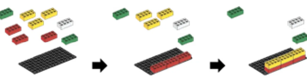
1.3.2 System architecture as Lego blocks
System architecture can be exemplified by building a Lego construction. First we have to define the structure of the Lego blocks, or the components. We must decide how the blocks fit together, e.g. the bulges on top the blocks, and their dimensions, e.g. length and width. Second, we have to de-fine the relation between the blocks, or components. We may decide that a yellow Lego block always must be placed on a red block. Third, we must decide the environment to build our construction on. In the Lego case, we might choose a Lego plate where we attach the lower layer of the Lego blocks. Fourth, we have to give some guidelines for the design and devel-opment of the construction. It may be to start building the construction from the bottom and up. Figure 1 illustrates system architecture as a construction of Lego blocks.
Figure 1. System architecture illustrated as Lego blocks. The black plate corre-sponds to a system platform on which system components are connected through
well-defined interfaces (bulges).
In reality, these blocks are software code or hardware components. When we refer to these components, we mean components on different levels. Both in hardware and software components are often composed of other compo-nents. Sometimes the component itself is a system, with its own architecture.
These components, or sometimes subsystems, have interfaces which they use to communicate with other components. For a hardware component this interface is often a connector to which an electrical wire is connected. For a software component, the interface might be a shared memory space, a sock-et, or a procedure call.
The environment that we build the system on might be an operating sys-tem, such as Linux, and for hardware the printed circuit board, where our components are mounted. The system cannot be a system by itself without any communication with the outer world. It must be able to input and output data from its environment. In a car this input might be a signal saying that the driver is braking. An output may be a tell-tale saying the car engine is out of oil.
Before designing a system, a procedure or principle for how to construct it must be set. We can choose if any software should be included or not. We can choose if we are going to construct the system from our existing compo-nents from earlier developed systems, or if we are going to create everything from the beginning. We must also decide if we follow strict routines. A cru-cial step, before constructing the system, is of course to decide the aim of the system, if any specific requirements have to be fulfilled, and if certain rules have to be obeyed for the completed system. We must also know about which budget we have.
1.4
Thesis outline
This introduction is followed by Section 2 that formulates the research prob-lem with corresponding research questions and explains the research meth-ods used for answering these questions. In Section 3, the results are present-ed and discusspresent-ed. Section 4 gives an overview of relatpresent-ed literature and re-search. Section 5 concludes the thesis results and contributions, and proposes future work. The thesis is followed by an appendix with the appended pa-pers.
2.
Research scope
This section will present the research problem and the stated research ques-tions, followed by the method we used to answer these questions. The four empirical studies we have conducted will also be presented, and these are further described in the appended papers.
2.1
Problem formulation
Many companies that develop embedded systems will at some point perform a refactoring of their system architecture. One example is Volvo CE, a pro-vider of construction equipment. To cope with a product range of at least 150 machine models, Volvo CE uses a product-line approach where an elec-tronics platform is shared between the products. This platform includes in-ternal and exin-ternal system communication, diagnostics, logging, I/O han-dling, systems handling etc. On top of it, machine specific applications are added. Volvo CE is now facing an updating of the platform. The next archi-tecture is AUTOSAR based and includes technology, methods, and tools for the electronics systems of all products developed by the Volvo group.
The change to the new architecture may affect many aspects of Volvo CE electronics systems, such as aftermarket tools, software structure, communi-cation protocols and development tools. The system architects at Volvo CE have a major work ahead of them, but still know little about how the compa-ny and the products will be affected. If the new platform is not successfully introduced, there are risks of delayed development projects.
Several standards for system development exist today. For the architect, the standard ISO/IEC 42010 [12] is of interest. It concerns how architectural descriptions should be expressed to facilitate communication around, and the development of, the architecture. ISO/IEC 15288 [13] describes the life cy-cle processes associated with human-made systems, and also processes needed for support of the life cycle processes. It is aligned with ISO/IEC 12207 [14] which is more concerned with the development of software sys-tems. IEEE 1220 [15] gives a more detailed description of the life cycle pro-cesses than the other two. There are also a number of books in the area of system architecting, such as “The method framework for engineering system architectures” by Firesmith et al. [16], “Software architecture in practice” by by Bass et al. [7] or “System Architecting” by Muller [17].
All these standards and books mostly concentrate on the development of new products or new features, and contain only some smaller elements of processes for system evolution. Despite the extensive literature, there is a lack of descriptions of activities in the system refactoring process. Most lit-erature and research focus on new product development.
This gap between existing development knowledge and the system refac-toring process causes problems for the system architects at Volvo CE and at other companies. It is not easy to understand the benefits and costs, and to explain how it will affect the company in terms of reduced costs and hence motivate management about the proposed changes. When the system archi-tect dearchi-tects the need of refactoring the system, he needs to argue why extra resources are required on system architecture activities. He needs to investi-gate how the changes affect the system and the organization, and how the organization should be prepared. During this process many decisions must be made under time constrained conditions. The problems that may occur are:
Poor predictions of effects on development effort and costs, due to sys-tem adjustments, education needs, new test environment etc.
Risk of important stakeholders missed or involved late, from aftermar-ket, product planning, production etc.
Risk of unwanted or unplanned technical effects when performing refac-toring, e.g. quality problems, and supplier compatibility.
Risk of unwanted or unplanned organizational effects when performing refactoring, e.g. undefined roles, responsibilities, and processes. Lack of organizational support, due to poor communication between
system architects and management, and between co-workers.
Risk of delayed time-to-market, due to poor planning and unexpected effects.
The purpose of our research is to find out how we can help the system ar-chitect in the work of refactoring a system and from that create a guideline. The guideline will assist the system architect in preparing and explaining system refactoring to the organization. This thesis describes the initial re-search where the guideline is outlined by exploring the system refactoring process.
2.2
Research questions
Three research questions have been stated to explore the system refactoring process.
2.2.1 RQ 1: Which effects can be expected from a system
refactoring?
We believe that system refactoring causes effects on both system properties and on the principles for its development and evolution. We also believe that system refactoring causes effects throughout the whole life cycle of the product, and the corresponding processes in the company.
By answering this question we will understand the consequences of a sys-tem refactoring, in terms of impacts on syssys-tem properties, on the company and on their intra- and interrelationships. This is important for decisions relating to the choice of the technical solution, and to planning and prepara-tions of system refactoring changes.
2.2.2 RQ2: What are the drivers of system refactoring
decisions?
We believe that the drivers behind refactoring of embedded systems are both business-related and technical. We also believe that practicing system archi-tects tend to analyze the technical aspects more than the business aspects.
By answering this question we can guide the system architect when col-lecting information and performing analyses, that will be used as decision-support by management.
2.2.3 RQ3: What would a guideline need to contain to support
system refactoring?
We believe that certain activities are more important than others, in the sys-tem refactoring process. We also believe that the characteristics of the pro-cess differ from the normal system architecting propro-cess. We also believe there is a difference in the need of guidance to succeed with an activity.
By answering this question we will understand what activities need to be described in a guideline for the system refactoring process.
2.3
Research method
The starting point was to help Volvo CE prepare themselves for a system refactoring, but we saw a knowledge gap of the system refactoring process
and its effects. Therefore, we chose to gather information from companies developing products with similar systems. To answer our research questions, we have chosen to look at the system refactoring process in companies pro-ducing distributed embedded systems, especially for automotive systems.
Most of our studies have been in Swedish companies. In total, 15 compa-nies and 44 respondents have been involved in our studies. This is because of availability, and because they are representative of other similar compa-nies in the world. The studied compacompa-nies have their operations or parts of operations spread around the globe, with activities in Europe, Asia, North America, and South America. However, three companies have their devel-opment organization located only in Sweden. We have studied system refac-toring from the perspective of electronics systems development as spectators that tried to penetrate into the process from outside to collect data from the visited companies or from other studies.
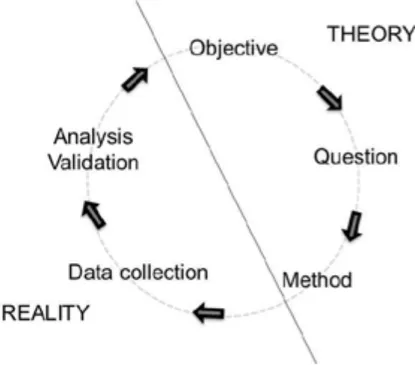
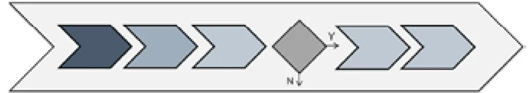
Our research process can be described as a cycle, oscillating between the-ory and reality. We had a purpose and knew what to achieve, which raised a first question. To answer this question, we chose relevant methods of data collection and analysis. Using the knowledge we received from reality we were able to start fill the theory knowledge gap and identify new issues that were needed to be answered to fill the gap completely. This research process is illustrated in Figure 2
Figure 2. An illustration of the research process oscillating between theory and reality.
The research described in this thesis can be described as a first step to-wards achieving our ultimate goal, which is to create a guideline for the sys-tem refactoring process to be used by syssys-tem architects. Therefore the first part is descriptive, where different phenomena have been explored, with the purpose to describe the reality today. The questions we have been asking are of the exploring type “What?”. We have chosen to look at the characteristics that describe the system refactoring process, i.e. what starts the process, what is included in the process and what the outcome of the process is.
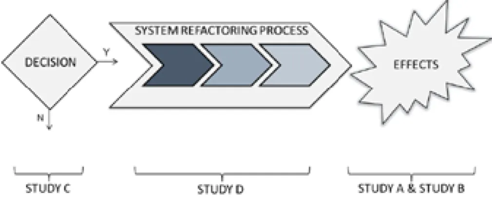
Figure 3. The relation between the four conducted studies and the system refactor-ing process.
The empirical collecting of data has been mainly qualitative. The methods used for collecting data are case studies [18, 19], systematic literature re-views [18, 20], interre-views [18], and survey questionnaires [18]. Both qualita-tive and quantitaqualita-tive analyses have been performed on the collected data. This inductive approach is suitable when we try to create general theories from human experiences and from environments where a lot of complex relationships reign [21].
Four studies were conducted to answer our three stated research ques-tions. The relationships between the studies and the investigated parts of the process are illustrated in Figure 3. Below, we will present the four studies in terms of purpose, method, analysis and validity threats. For one conducted case study, the context is further explained to give background of the com-pany situation. The validity threats [18], we are discussing in this section are against:
Construct validity is related to the ability of the results to be generalized to theory and concerns the design of the experiment.
Internal validity is related to the fact that the results are a causal effect of the used methodology.
External validity is related to the ability to be generalized into practice. Conclusion validity is related to the ability to draw the correct conclusion about relations between the treatment and outcome.
2.3.1 Study A. An explorative case study of system
refactoring effects
Purpose
To answer the first research question an explorative case study was per-formed in a company that was going to perform a major system refactoring. The study aimed to investigate the introduction phase of the software archi-tecture at Volvo CE, a producer of construction equipment. We wanted to see how the company was affected by changes in different architectural ele-ments in terms of costs and benefits.
Context
Volvo CE is part of the Volvo group, which is one of the world’s leading suppliers of commercial transport solutions with products like trucks, busses, construction equipment, drive systems for marine and industrial applications, and aircraft engine components. Today the Volvo group has customers all over the world, mainly in Europe, Asia and Northern America.
Volvo 3P is responsible for product planning and global vehicle devel-opment for the global truck operations of the entire Volvo group. In order to manage the increasing complexity of the electronics systems in new genera-tion vehicles, Volvo 3P has performed a radical system refactoring on the electrical and electronic architecture and introduced AUTOSAR (see Section 1.3). Volvo 3P hopes that this will reduce the development cost, give more flexibility to meet new technologies and standards, to be able to be first on the market with new features, to meet brand differentiation while maintain-ing a high degree of commonality, and to achieve multi-site development.
Volvo CE is a producer of construction equipment. Their product range includes 150 different machines, such as wheel loaders, excavators, haulers, and road machinery. The electronics system constitutes an increasingly im-portant part of the functionality in a modern construction machine. In order to meet the demands on business, safety, and development time Volvo CE adapts the development method to a more product-line oriented approach based wholly on an electronics system platform. This includes working on development processes, architecture, tools, and system modeling.
By sharing tools and components, such as engines, within the Volvo group, the companies can take advantage of higher volumes and reduced costs. Therefore, Volvo CE will also adapt to the new Volvo 3P architecture. The architecture consists of a common software platform which includes
communication, diagnostics, logging, mode management and power state management.
Method
This study was based on interviews with 11 persons at different positions in the electronics development department of Volvo CE. The new architecture was also investigated through reading specifications. The interview ques-tions had a life cycle perspective and were related to effects on system prop-erties and the company when introducing the new system architecture. The interviews were performed in a semi-structured way. Pre-defined questions were constructed but also followed by deeper questions related to the given answers. To ensure that all matters were covered the interviews ended by giving the respondents the opportunity to share additional information. The interviews were audio recorded and notes were taken. Each interview was summarized in text and sent to the respondents for approval before analysis.
The method was chosen because of its explorative character. Interviews gave the possibility to get the answers that were not expected when planning the study.
Analysis
After data extraction, the identified effects were mapped into a matrix. The matrix rows corresponded to the architecture element that caused the effect. The columns were divided into two parts, capturing affected system proper-ties and affected company functions, respectively.
In this way we were able to identify what in the company or in the elec-tronics system that was affected by a change in a certain architecture ele-ment, and also how it was affected.
Validity
When analyzing the extracted data from the answers we constructed an anal-ysis matrix that helped us ensure that all relevant effects had been consid-ered, which strengthened the construct validity of the study. The study re-sults were based on expectations prior to performing the refactoring and therefore the internal validity was not evaluated. The study was conducted at a specific company and therefore the situation at another company could differ and the results may not be directly applicable at a different company or on a different architecture.
Presentation
The study was presented at the 36th EUROMICRO Conference on Software Engineering and Advanced Applications (SEAA) in Lille 2010.
2.3.2 Study B. A systemic literature review of AUTOSAR
effects
Purpose
Since the first study only investigated effects from system refactoring in one company an additional study was conducted to help answer the first research question. The AUTOSAR architecture will be adopted by almost the entire automotive industry in Europe and Asia. Therefore AUTOSAR gave an op-portunity to study the implementation of the same architecture in several products and hence an opportunity to compare reported effects of system refactoring with each other. Hence a systematic literature review of imple-mentations of AUTOSAR gave the possibility to summarize these reported effects. The results also strengthened the internal validity of Study A.
Method
A systematic literature search was made for papers describing experiences from introducing AUTOSAR.
Analysis
The analysis was performed in a similar way as in Study A. An analysis matrix was constructed where each identified reported effect was mapped to the elements in AUTOSAR that caused the effect, and to the functions in the company that were affected and properties of the system.
Validity
Since the architecture is introduced stepwise in products and so far only to some extent, only a small sample was found, and which threatened the inter-nal validity. To deal with construct validity a review protocol was devel-oped, where background, objectives, research questions, strategy, sources, and search criteria were pre-defined, according to the advices of Kitchenham [20]. During the process all the found literature and the exclusion criteria have been documented. As the implementation of a specific architecture was studied the results might not be directly applicable for implementations of other architecture. Still, this is an automotive standard and therefore there might be a possibility to generalize the results to other implementations of the same architecture in other automotive companies not covered by this study. There are initiatives in other industrial domains, such as avionics [22], that share similar features, and thus a possibility exists for some results to be applicable in those domains.
Presentation
The result of the study was presented at the 37th EUROMICRO Conference on Software Engineering and Advanced Applications in Oulu 2011.
2.3.3 Study C. Scenario-based interviews of system
refactoring drivers
Purpose
The aim of the third study was to find the drivers behind a decision of sys-tem refactoring and to answer our second research question.
Method
14 interviews were conducted at eight companies that produce distributed embedded systems. The respondents were persons used to make decisions about the system architecture and amongst them were seven system archi-tects and seven managers at different levels in electronics development. The companies and respondents were chosen from their availability and willing-ness to participate.
All interviews began by giving a start scenario to the respondent. The start scenario represented a suggestion of a change to be made in the embed-ded systems in the companies’ products. The respondent was then asked to request the information he needed to complete the decision of whether the system change should be performed or not. After the respondent answered, additional pre-defined information related to the requested information was given. The respondent was once again asked to request the information he needed to complete the decision. This procedure was repeated until the re-spondent answered that he was able to complete the decision or at least make a recommendation.
If the respondent asked for information that was not pre-defined and nev-er requested in the previous studies, new information was created on site and stored in the list of pre-defined information. In that way we were able to catch cases we did not expect beforehand.
Analysis
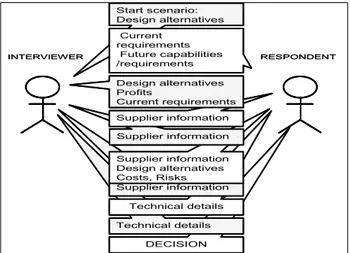
The requested information from each interview was categorized into infor-mation areas. We investigated the most important decision criteria by per-forming frequency analyses, where the information areas that most respond-ents had requested were found. To further elaborate the important criteria, the interviews were re-written in a formal way where the requested infor-mation was replaced by the corresponding inforinfor-mation area, see Figure 4. Then we compared if the first requested information areas corresponded to the most wanted information.
Differences in answers between system architects and managers, between an industry sector and the rest of the group, and between one company and the rest of the group, were analyzed by Chi-2 calculations.
To capture to what degree the effects on the company is investigated be-fore a decision of system refactoring is made, the requested information was
mapped to one or several company functions. It gave a possibility to see for which parts of an organization the effects were investigated before making the decision.
Figure 4. An illustration of a typical interview described in a formal way.
Validity
The reason why this study was conducted through interviews and not through questionnaires was to cover the reasoning behind the answers. The planning phase of the study included literature studies on architecture evalu-ation methods, and return-on-investment analyses. To strengthen the external validity the respondents were chosen from companies in different domains. A threat against internal validity was the selection of scenarios. It is hard to select general scenarios which can be applied in all types of domains. The interpretation of the scenarios might differ between different domains. Presentation
The study result was presented at the 10th Annual Conference on Systems Engineering Research (CSER) in St Louis 2012.
Start scenario: Design alternatives Current requirements Future capabilities /requirements DECISION Technical details Technical details Supplier information Supplier information Design alternatives Costs, Risks Supplier information Supplier information Design alternatives Profits Current requirements INTERVIEWER RESPONDENT Start scenario: Design alternatives Current requirements Future capabilities /requirements DECISION Technical details Technical details Supplier information Supplier information Design alternatives Costs, Risks Supplier information Supplier information Design alternatives Profits Current requirements INTERVIEWER RESPONDENT
2.3.4 Study D. A survey of system refactoring activities
Purpose
The fourth study aimed to answer the third research question. By identifying which activities are included in the system refactoring process, we could start to sketch out a proposal for a guideline to be used by system architects. Method
Data was collected by using a web-based questionnaire. 34 respondents from 14 Swedish companies that develop products with embedded systems an-swered the questionnaire. The responsibilities of the respondents were within system architecting, system design, system development, project manage-ment, systems engineering, and management.
The survey questionnaire contained a first part that described what a typi-cal system refactoring is. Then the respondents were asked, for each of 35 activities, to rank how important the activity is for the system refactoring process and how helpful a guideline would be to succeed with the activity. The 35 activities were identified through literature studies of conference papers, books, and systems engineering standards, and through findings from earlier conducted studies. The activities were reviewed in several cycles by four persons experienced within system engineering research and practice. Before releasing the questionnaire, a pilot study was conducted.
Analysis
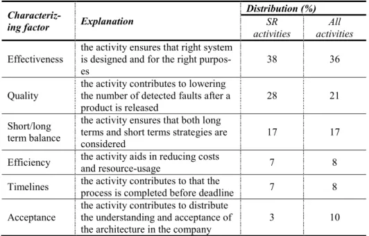
In the analysis the activities were grouped into the categories “Most im-portant for the process”, “Imim-portant for the process” and “Not imim-portant for the process” depending on the lower limits of the confidence intervals of the responses for each activity. The Wilcoxon rank sum test provided the calcu-lations. In the same way the activities were also investigated to see how much support the respondent wanted for each activity. The analysis further investigated differences in responses amongst the respondents with different responsibilities. Through the literature studies we also identified characteriz-ing factors for the general architecture processes. The activities that had been chosen as most important or only important were mapped against it to see if they contributed to each of these characterizing factors. The mapping was then used to identify the characteristics of a system refactoring process. Validity
Possible validity threats against the outcome of this study were the uneven distribution of respondents on the participating companies and the choice of activities that were going to be rated by the respondents. To ensure that the results would reflect the real world as much as possible, we wanted as many respondents that we could find in Sweden. However, this resulted in that the
amount of respondents from each company varied and that might be a threat against the conclusion validity and the reliability of the measures. To avoid threats against construct validity, we tried to identify the activities from sev-eral sources, both from academic papers and systems engineering standards as well as from earlier experiences and studies. Also, pilot studies with sys-tem architects were conducted, which also strengthened the internal validity. Presentation
The study result has been submitted to the Seventh Workshop on SHAring and Reusing architectural Knowledge (SHARK 2012) that will be held in Helsinki, Finland, in August, 2012.
3.
Results
As described in the previous chapter, four studies were conducted to answer our three stated research questions. In this chapter the results and answers are presented for each question.
3.1
Which effects can be expected from a system
refactoring?
The appended papers A and B describe the studies that were conducted to answer our first research question. The results from study A are based on interviews about expected effects, conducted at the electronics development department at a construction equipment producing company, which was just about to perform a system refactoring. Study B is based on a systematic lit-erature review of reported observed effects from the introduction of AU-TOSAR, an automotive open standardized software architecture. The effects were reported mostly from industry, but also from academic research.
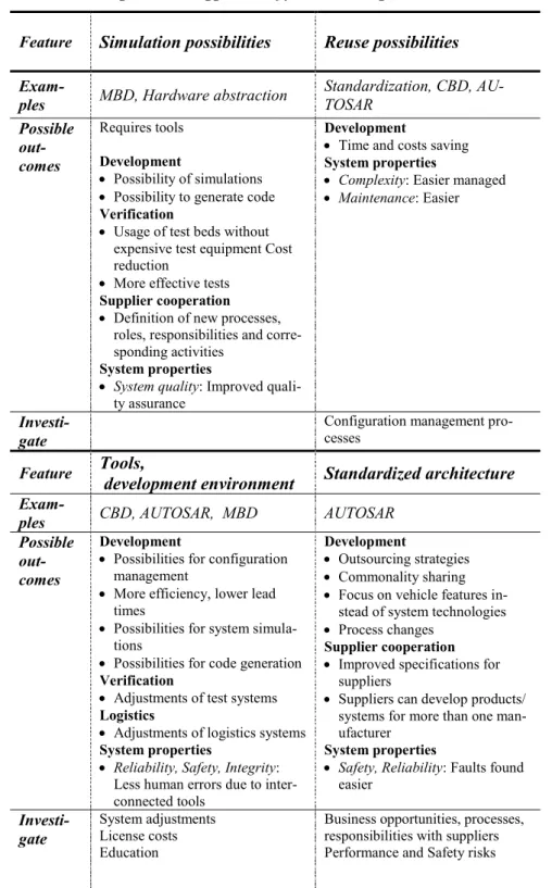
Table 1 gives an overview of possible outcome from features typically in-cluded in architectural changes. These features were inin-cluded in the studied architectural changes in study A and study B. The overview shows possible effects that we found in these studies and gives examples of in which types of architectures the features can be found. The overview also suggests fur-ther areas for investigations. These suggestions are also based on findings of effects from study A and study B. The overview can be used for finding relevant areas to investigate when preparing for refactoring of systems. Giv-en a specific refactoring, e.g. the introduction of AUTOSAR, all the columns must be considered that are relevant, i.e. what has to be examined will be a combination of several columns.
Table 1. Possible outcomes from features included when refactoring architecture, given with suggestions of further investigations.
Feature Simulation possibilities Reuse possibilities
Exam-ples MBD, Hardware abstraction Standardization, CBD, AU-TOSAR Possible out-comes Requires tools Development Possibility of simulations Possibility to generate code
Verification
Usage of test beds without expensive test equipment Cost reduction
More effective tests
Supplier cooperation
Definition of new processes, roles, responsibilities and corre-sponding activities
System properties
System quality: Improved quali-ty assurance
Development
Time and costs saving
System properties
Complexity: Easier managed Maintenance: Easier
Investi-gate Configuration management pro-cesses
Feature Tools, development environment Standardized architecture
Exam-ples CBD, AUTOSAR, MBD AUTOSAR Possible
out-comes
Development
Possibilities for configuration management
More efficiency, lower lead times
Possibilities for system simula-tions
Possibilities for code generation
Verification
Adjustments of test systems
Logistics
Adjustments of logistics systems
System properties
Reliability, Safety, Integrity: Less human errors due to inter-connected tools
Development
Outsourcing strategies Commonality sharing Focus on vehicle features
in-stead of system technologies Process changes
Supplier cooperation
Improved specifications for suppliers
Suppliers can develop products/ systems for more than one man-ufacturer
System properties
Safety, Reliability: Faults found easier
Investi-gate System adjustments License costs Education
Business opportunities, processes, responsibilities with suppliers Performance and Safety risks
Feature Hardware abstraction Well-defined and clear in-terfaces and specifications
Exam-ples MBD, AUTOSAR Standardization, CBD Possible
out-comes
Development
Development of hardware and software in parallel
Verification
Integration and verification faster
Supplier cooperation
New working models for suppli-er coopsuppli-eration
System properties
Reusability: Possibilities to reuse software components be-tween products
Possibilities to reuse hardware components between products Flexibility: Easier to move the software components between different control units, Easier to add new software functionality without the need of integrating an additional control unit into the system
Safety: Lower the risk for inte-gration problems
Development
Less time is needed on calibra-tion and validacalibra-tion
Supplier cooperation: Im-proved specifications given to suppliers
Improved quality of components delivered by suppliers
System properties
Complexity: More controllable Flexibility: Improved
Reliability: Improved reliability, less human erroneous interfer-ence
Safety: Lower risk for integra-tion problems, faults found ear-lier
Investi-gate
3.1.1 Effects on company
Both studies imply that a large system refactoring has company impacts. It is important to consider these impacts to avoid delays in product development projects.
System development
When the changes in the architecture include new development tools or whole tool chains the development organization should prepare itself in time for several things. Resources must be spent on adjusting current existing tools to the new tool chain. A new tool chain will also affect the way of working and new processes and responsibilities must be set. This also means that the staff needs education on how to work with the new tool and how to adapt it into existing development systems. If this is done properly the bene-fits, which come at a later stage, can include a more efficient development process with shorter lead times, and improved possibilities for configuration management. A remaining cost will probably be expensive licenses. Typical architectural changes that include new development tools are introduction of model-based development or changes of component models. Model-based development also gives possibilities for code generation and component based development also probably needs less time on calibration and valida-tion in the long run. Another way of shortening lead times in the develop-ment process is to develop hardware and software independently of each other, since they can be developed in parallel and hence make both integra-tion and verificaintegra-tion faster. Then it is important to use clear interfaces and standards. Our results also imply that standardization makes it easier to change software design at later stages in the process and that manufacturers can focus on product features instead of on system technologies. On the neg-ative side this also requires process changes. Our studies imply that architec-tures that allow reusability, as product platforms, or component-based sys-tems, save time and costs in system development.
System verification
In the verification phase, model-based design, component-based design, hardware abstraction or the introductions of new standards call for new tools. It is then beneficial to choose tools that allow verification by model simulations in virtual environments. These environments can simulate bus loads and simplify verification of subsystems. In this way the verification can be performed already in early development phases and without expen-sive test beds. Also the use of clear interfaces and specifications means that faults are found earlier. Finding faults early is also important to keep the maintenance effort low.
System maintenance
By using model-based design, standardized architectures like AUTOSAR, or components that have been proven-in-use, maintenance seems to be made easier and faults are found earlier. Standardized architectures, like AU-TOSAR, seem to give a possibility to maintain a large product range. Supplier cooperation
Using a standardized architecture, like AUTOSAR, or components with well-defined interfaces means that the specifications given to suppliers for purchase are improved. Then there is less space for misinterpretations which in turn gives higher system and software quality. Standardization gives pos-sibilities for reuse and hence opens doors for new business opportunities. The manufacturers can outsource or buy the development of components and subsystems. The suppliers can offer the same features to several customers instead of customized features to specific manufacturers. The manufacturers can then concentrate more on product specific features instead of system details. The initial costs relate to defining new business strategies, such as product portfolios, responsibilities, new tools etc. Changes to a new standard also lock out suppliers that have not adapted to that standard. For instance, a change to AUTOSAR, for a construction equipment manufacturer, may not be beneficial since most suppliers are not within the automotive domain. This also applies to minor changes, such as replacing the protocol used for external communication. Therefore the manufacturer has to investigate ef-fects of this kind of changes, not only on the system level but also on the company level. Other changes that might affect the cooperation between manufacturers and suppliers are if the supplier needs to install or adapt the development environment to fit in the system architecture of the manufac-turer. It might lead to a situation where the supplier has to invest in expen-sive licenses or refuses to take responsibilities for his delivered components or subsystems in the final product.
Other effects on company
We have also seen that parts of the company that are not directly connected to the development organization can be affected by system refactoring. Changing the external communication, such as replacing the diagnostics protocol or download mechanism, can affect the aftermarket or production, where new tools have to be developed. Also new diagnostics or logging ca-pabilities might give the product planning and sales new opportunities.
3.1.2 Effects on the system
System properties can be divided into two categories. The first category is the properties that are related to the ability of the system to perform its tasks, such as performance and reliability. These are often inter-connected and sometimes effects on one property gives effects on another. For instance, better security against intruders that can alter code or inter-connected sys-tems that lessen human interference improve the system integrity. Then, fewer faults can be implemented, intentionally or accidentally, which also strengthens the reliability and the safety of the system. Other changes in the system that give positive effects on reliability and safety are using standard-ized architectures or components with clear interfaces, since less error-prone interpretation is needed. Also the overall opinion is that the use of compo-nents that have been proven-in-use improves the system safety. Our studies of effects include the introduction of software platforms that give possibili-ties for the technology to meet future demands. These platforms usually of-fer a development environment that allows network management so that the system communication can be optimized which seems to improve the system performance. The negative effects are that these software platforms require a lot of memory and run-time themselves, which lowers the overall system performance.
The second category of system properties is the properties of the system that relate to how easy or manageable it is to work with. One such property is system flexibility. When investing in architectures, companies want the selected architecture to be capable of meeting future requirements on new features or legislation. These can be supported by architectures that isolate hardware and software from each other so that software components can be reused or added on several hardware nodes in the system. Other ways of enhancing the flexibility to add new functionality is to use well-defined in-terfaces between components or to use signal-based communication. Then, only communication databases have to be updated when adding a new soft-ware component instead of specifying the addresses for source and destina-tion in all affected components. Systems tend to become more complex over time but standardized, well-defined specifications and processes make them more controllable. This can be achieved by reusing well-known components in several development projects. By using software platforms where several software components are integrated, there is a possibility to integrate more software functionality in each hardware platform. This lessens the system communication and hence dependencies between nodes in the system. Reus-ability of components also seems to be crucial for maintaining large product ranges due to the well-known interfaces, specifications and documentation.
3.2
What are the drivers of system refactoring
decisions?
In the appended paper that explains study C, the results of the study that answers our second research question are presented. We wanted to under-stand the drivers behind system refactoring by looking at what kind of in-formation decision-makers investigated prior to a decision. The areas of information that most of the respondents asked for were regarded as most important for the decision. In this section we will present these information areas in order of importance.
3.2.1 Costs
Not surprisingly, information on costs seems to be the most important driver behind system refactoring. These costs relate to development, manufactur-ing, and maintenance, and they were requested by both managers and system architects, even though managers start to investigate costs earlier than sys-tem architects. The developments costs are related to software and hardware, licenses and support of tools. Manufacturing costs relate to hardware and components costs and the production. Maintenance costs are related to prod-uct management, i.e. the maintenance of the system components and the warranty costs.
3.2.2 Profits
Profits can be gained from both the technical advances and possible market opportunities given by the system changes. The profits gained from technical advances are increased quality, more system flexibility, modularity and bet-ter diagnostics. This in turn lowers the costs for development, shortens the development lead times, gives cheaper hardware, reduces risks in projects and simplifies the product management and the ability to add new function-ality into the system. The profits from market opportunities relate to the abil-ity of the system to offer new services to customers and the customers’ expe-rience of a better quality, which can give an increased sale. The decision-makers compare the profits against the costs of introducing the system changes and perform estimations on when return-on-investment (ROI) can be expected.
3.2.3 Supplier information
If the system change includes the possibilities of buying components from suppliers the decision-maker requests information about the supplier and the components. He wants to know the viability of the supplier, such as financial status and survival probability; can the supplier make long-term
commit-ments and what happens in case of bankruptcy? How is the market, are there other suppliers? The decision-maker also wants to know if the component is newly developed and the supplier’s experiences of the technology. The sup-portability of the supplier is investigated and how the supplier handles change issues. What will the cooperation look like, the ownerships and re-sponsibilities? If a components is going to be purchased it must be cost ef-fective, so the business model and license agreements are considered. The component itself must fulfill desired requirements. Much of this investiga-tion involves the purchasing department.
3.2.4 Technical details
Both system architects and mangers want to know technical details. They want to know how the proposed system changes will fit the current architec-ture and which system changes are required to make a solution effective. Typical questions concern interfaces, electromagnetic compatibility (EMC), compatibility with internal proprietary and standardized communication protocols, hardware needs, tool needs, and if changes can be made step wise. Other issues relate to system quality attributes, such as performance and complexity. It is also important to consider the product life cycle stages, such as supportability and aftermarket, and the product strategies, such as the “look-and-feel” of the product.
3.2.5 Future requirements
When investing in changes to the system or system architecture the decision-makers must be sure that the future system requirements are considered. Therefore coming functionality, legislation, technologies, and future stand-ards, are identified and investigated, often several years ahead the introduc-tion of them. The decision-maker must be sure that the system will be able to meet these future requirements and investigate the ability of the system to evolve and accommodate new technologies. For example, what happens at the end-of-life for a hardware component? Can it be replaced by a similar component? Does the system provide possibilities for incorporating new services? Can it be reused in future products?
3.2.6 Current requirements
Also short-terms goals have to be considered. Existing problems in the cur-rent system have to be identified. The decision-maker must understand cus-tomer benefits and requested functionality. If there is an infrastructure that is expected to be used across the entire product-line, or across different com-panies or business units, the decision-maker must consider that the system
3.2.7 Enterprise constraints
Constraints of the enterprise concern strategic goals, including roadmaps, policies, and core business. Financing and available resources also affect the decision, as well as planned development projects and the maturity of the organization.
3.2.8 External constraints
There are also constraints from the outside world, such as current laws, regu-lations, specifications, standards, and guidelines. They may concern safety, communication protocols or vehicle emissions and affect both the system needs and the market deadlines. Existing technologies and competitor prod-ucts are other drivers for system changes. It is also important that the system is able to meet safety regulations and other legislation on different markets.
3.2.9 Design alternatives
In a refactoring decision several solution options have to be identified and considered, such as the possibilities to reuse old subsystems and compo-nents, and if there are possibilities to buy solutions from suppliers. Economic analyses of the different design alternatives affect the decision. Supplied products are further investigated according to Section 3.2.3.
3.2.10 Risks
Less than half of the participants asked for information about risks during the scenario-based interviews. The requested risk information concerned commercial risks, such as the risk of delays for time-to-market, and technical risks, such as increased system complexity, technical faults, and if new tools were hard to work with.
3.2.11 Human requirements
Only a few participants requested information about the human require-ments, such as process changes, responsibilities and the need for education. Some participants emphasized the importance of having support from the organization, both from upper-management and colleagues, prior to the deci-sion.
3.2.12 Technical management
Only one participant wanted information about the technical management and configuration of the system solution. He mentioned the importance of
having ways of working that ensured that a chosen system solution did not evolve differently between different company departments.
3.3
What would a guideline need to contain to
support system refactoring?
The last study aimed to answer our third research question and is presented in the appended paper D. The result from the study is based on a survey questionnaire which was given to senior system engineers, mainly system architects, employed at Swedish companies that develop embedded systems.
3.3.1 Activities in system refactoring
From a set of 35 activities, which were identified as typical activities in gen-eral system architecture processes, 20 activities were identified as important for system refactoring. The ratings were made on a 0-6 Likert scale and ac-tivities with a lower bound above 4.0 for the median confidence intervals were considered as “most important”. Table 2 shows all the activities and their calculated confidence intervals. The activities that were identified as “most important” are:
Establish the technical requirements for the system e.g. identify interfac-es and dinterfac-esign constraints
Investigate if the existing architecture can be expanded or adjusted to fit new requirements
Assess whether the identified architecture-alternatives meet the require-ments
Evaluate the effects of the identified architecture-alternatives on the system’s non-functional properties, e.g. response times, safety, security, etc.
Assess the abilities of the identified architecture-alternatives to be evolved, reused, and expanded
Assess the impact on system life cycle quality factors, such as produci-bility, verifiaproduci-bility, ease of distribution, usaproduci-bility, supportaproduci-bility, etc. and changes in the corresponding processes
Select architecture parts to be verified and the verification methods to be used
Select architecture parts to be validated and the validation methods to be used
Activities with confidence interval lower levels above 3.5 were consid-ered as “important”, and they are:
Find future product range and customer demand Analyze deficiencies in the current system
Assess ability of the current system to scale for future drivers, e.g. com-ing laws
Learn about technologies, system architectures and architectural practic-es
Define the characteristics required for the product to be cost effective over competitors
Define the requirements for different steps in the systems life cycle, such as development, verification, maintenance, etc.
Establish a requirement baseline of the system architecture
Develop and identify alternative architecture solutions and selection criteria
Investigate suppliers (internal or external), in terms of risks, licenses, costs, supportability, responsibilities, viability
Identify and assess commercial and technical risks Update and review the architectural description
Table 2. The found activities and their confidence intervals of the ratings, given by respondents, for importance and need of guidance.
Activity Confidence levels
Im-portance line need
Guide-Planning
1. Create an overall technical vision for the embedded
system 3.0-4.0 5.0-6.0
2. Find synergies within different types of products 3.0-4.0 4.0-5.0 3. Find out company vision, roadmap, core business
and policies 2.5-3.5 3.5-4.5
4. Find future product range and customer demand 3.5-4.5 5.0-5.5 5. Find future laws and regulations 3.0-4.0 3.5-5.0 6. Analyze deficiencies in the current system 3.5-4.5 4.5-5.5 7. Monitor trends in key properties of the system 3.0-4.5 4.0-5.0 8. Assess ability of current system to scale for future
drivers, e.g. coming laws 3.5-4.5 4.5-5.5
9. Learn about technologies, system architectures, and
architectural practices 3.5-4.5 4.0-5.0
10. Investigate coming technologies 3.0-4.0 4.5-5.0
Requirements
11. Define the characteristics required for the product
to be cost effective over competitors 3.5-4.5 4.5-5.0 12. Define the requirements for different steps in the
systems life cycle, such as development, verification,
maintenance, etc. 3.5-4.5 4.0-5.0
13. Establish the technical requirements for the
sys-tem, e.g. identify interfaces and design constraints 4.0-5.0 5.0-5.5 14. Investigate enterprise constraints, such as available
resources, competencies 2.0-3.5 3.0-4.0
15. Establish a requirement baseline of the system
architecture 3.5-4.5 4.5-5.5
Technical solution
16. Develop and identify alternative architecture
solu-tions and selection criteria 3.5-4.5 4.0-5.0
17. Identify make-or-buy alternatives 3.0-4.0 3.5-5.0 18. Investigate if the existing architecture can be
ex-panded or adjusted to fit new requirements 4.0-5.0 4.5-5.5 19. Investigate suppliers (internal or external), in terms
of risks, licenses, costs, supportability, responsibilities,