V¨
aster˚
as, Sweden
Thesis for the Degree of Master of Science in Computer Science with
Specialization in Embedded Systems
30.0 credits
CODE PORTING IN EMBEDDED
SYSTEMS: A CASE STUDY
Ali Alexander Mokdad
amd16003@student.mdh.se
Examiner:
Adnan Causevic
M¨
alardalen University, V¨
aster˚
as, Sweden
Supervisor: Nils M¨
ullner, Lennie Carl´
en Eriksson
M¨
alardalen University, V¨
aster˚
as, Sweden
Abstract
Code porting is a very known topic nowadays that brings some issues with it. It consists of translat-ing code runntranslat-ing on a specific platform, to run on a different one and adapt with the new hardware. This thesis aims to present code porting and find possible guidelines to be applied when being per-formed, and contributes at the same time to the state of the art of code porting in embedded systems. Also, test these selected guidelines in a case study to validate whether they can be applied for each action of code porting. The case study consists of an autonomous underwater vehicle having a proportional integral deivative (PID) that is ported into a new hardware according to the selected guidelines.
Table of Contents
1 Introduction 3 1.1 Problem Formulation . . . 3 1.2 Research Questions . . . 3 1.3 Thesis Contribution . . . 4 1.4 Thesis Outline . . . 4 2 Research Method 5 3 Related Work 6 3.1 Code porting . . . 63.2 AUVs and PIDs . . . 8
4 Case Study Design and Planning 10 5 Implementation 13 5.1 Header Files . . . 13
5.2 Read IMU Sensor Data . . . 13
5.3 PID Controller . . . 14
5.4 Tasks and Scheduling . . . 16
6 Extracted Guidelines 18
7 Discussion And Limitations 19
8 Conclusion And Future Work 20
1
Introduction
Software portability is applied to indicate how easy an application can be transferred from one computer environment to another. Portability means the ability of moving an application across different operating systems, computer hardware, and environments. Furthermore, some software is easier to port than other software. A computer environment has a much wider definition, and could include the hardware, the operating system, and the interfaces with other software.
There are many reasons for porting programs to a different language. The reason could be language-level security or perhaps the platform might only support a specific language. The language experience of a developer, personal preferences, availability of existing libraries or co-development for other targets might be reasons to perform new implementations in different lan-guages [1].
In some cases, the porting effort consists of recompiling the source code. But sometimes it is necessary to rewrite major parts of the software. For instance, operating system functions or third party libraries may not always be available on the target system. In addition, some functions can be available on the target system, but perform a slightly different behaviour. The program code itself can also consist of unportable functions, like the paths of include files for example.
Portable software has several advantages over completely new software implementations, in-cluding increased programmer productivity and increased software flexibility and maintainability. As hardware development proceeds, the availability of better performance and functionality might cause replacement of the initially employed hardware. The more the software is developed to be highly portable, the more it might fit with the changes and continue to be employed with less adaptation.
In addition, code porting covers the operating system (OS) employed, where it becomes more complicated to be performed. The OS is an extremely important subject, but when it comes to its design, there is no specific approach concerning OS development and adjustments [2] to make a not working system work just by adjusting its OS. This causes a problem in embedded systems development, since the source-code needs to be modified every time new hardware requirements are demanded. Most OS adjustments and modifications are based on a trial and error approach, which is not an ideal solution for this problem. Although there are some generic development methods applicable for OS development, a formal approach is needed to prove if a general methodology could be applied in porting between OSs. The biggest motivation for this research is the ambigu-ity of a specific methodology for porting OSs in ES. This thesis provides a case study aiming for finding some guidelines to perform that job.
1.1
Problem Formulation
Code porting between languages can be very difficult and time consuming since it consists of chang-ing the computer environment [1,3]. Complex software has limitations, which lead to a conclusion that no software is perfectly portable, meaning that the ported software cannot work the same as the initial software. One of the common motivations to port code is that the new requirements de-mand more memory, but platforms are commonly inherently confined when it comes to expanding their memory. The new platform can facilitate more memory but the code needs to be ported [4]. There has to be some guidelines to apply when porting code, to obtain better portability results of a system.
1.2
Research Questions
This thesis addresses the following research questions:
2. Can we apply these guidelines when porting code from ADA to C, and how successful are these guidelines?
3. What are the best practices or strategies if there are no guidelines?
1.3
Thesis Contribution
The concrete contributions to the state of the art are: First a comparative literature study on code porting. The second contribution is the actual implementation of code porting based on the case study. The third contribution would be a critical review of how well the guidelines established based on the literature review, are applicable in the terms of that specific case study.
1.4
Thesis Outline
The thesis is organized as follows. Section2states the way of work applied in order to answer the research questions, specify guidelines and draw conclusions. Section 3 includes all the scientific literature regarding guidelines for code porting and case study related topics. Section4shows the specific case study employed in order to test the code ported according to specified guidelines. Section5 shows the implementation of the work applied in the case study. Section6 presents the guidelines selected according to the literature study performed, and how they are executed in the case study. Sections7presents the discussion and limitations of the implemented work, leading to Section8where a conclusion is extracted and future work is declared.
2
Research Method
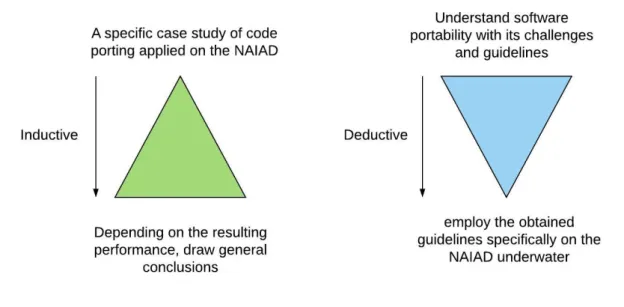
This work focuses on conducting a combination of deductive and inductive research. The deductive research is presented in Section3by a literature study having the goal of understanding software portability with its challenges and guidelines. Then the research is narrowed to employing these guidelines specifically an autonomous underwater vehicle (AUV) called NAIAD in a dynamic en-vironment (underwater) and adapt to different changes in that enen-vironment.
The inductive research is presented by performing a specific case study of code porting applied on the NAIAD, and depending on the resulting performance, general conclusions could be drawn. Changes in the implementation can be made after starting the work, and more improvements will be made to reach the best solution. Figure1 shows a brief explanation of the inductive and deductive reasoning applied in the thesis.
Figure 1: Inductive and deductive reasoning.
The Empirical method is exploited in this thesis according to three main steps:
• Perform the experiment: Specify guidelines applied for code porting on an embedded system. • Check how it turns out: Apply the selected guidelines when performing code porting on the
NAIAD.
3
Related Work
There are two important aspects to this thesis. One of them is the guidelines for code porting, related work about these guidelines is discussed in Section3.1. The second important part focuses more on the actual case study, to investigate these guidelines and show how they are applied. It holds relevant work regarding the case study, which focuses on PID controllers and AUVs as discussed in Section3.2.
3.1
Code porting
This section includes researches and work related to the guidelines of code porting. As the main sources to get this through, papers [2, 5] were selected. In paper [2], written by ”Osvaldo de Souza” and ”Helano S. Castro” having the title ”A complete method for porting operating system for embedded systems”, the authors propose a complete method to port the OS into a new hardware platform. In paper[5], written by ”James P. Pennell” having the title ”An Assessment Of Software Portability And Reusability For The WAM Program” investigates the levels of portability and reusability needed in a World Wide Military Command (WAM) program and develops a plan to ensure that these levels are achieved. From these papers, the authors deemed the following guidelines as important:
• Evaluate requirements through decision making support:
As discussed in [2, 5], the first step towards code porting is to do a requirement analysis. This step submits the initial decision to select a decision making model of the new system. It checks if something needs to be redesigned or if the requirements for the new target platform have changed.
Decision making decreases the effort placed on less relevant phases of the project. It specifies hypothetically the best way of work in order to reach the specified goal. This may include reaching the planned result in the fastest or the more efficient way.
This step may also include creating models of the costs and benefits of equipment purchases and software installations.
If the plan is to change the hardware, a framework can be constructed to determine porta-bility requirements. The idea is to anticipate the need for replacing the hardware, to expect to gain certain advantages by this replacement hardware. After that, a comparison of those advantages to the expected costs of moving applications to the new hardware must be exe-cuted. There is no provided level of accuracy for this approach, but it is considered according to [5], to be a basis for determining required levels of portability. Also, considered neces-sary for conducting portability trade-offs against other characteristics like performance or development cost. An example of an approach for determining portability requirements is illustrated:
– Assume that the hardware is to be replaced on a five-year cycle.
– Assume that the performance and price of the replacement hardware improve according to historically established trends.
– Approximate the expected savings accompanied with purchasing the replacement hard-ware in five years.
– Estimate the loads of of applications software that needs to be ported to the new hard-ware.
– Evaluate the cost of transferring the applications to the new environments and comput-ers, by assuming several portability levels.
– Estimate the cost of attaining various levels of portability while the applications are being developed.
– Construct a portability metric that consists of costs and savings using an appropriate model.
– Determine desired and minimum levels of portability (using an appropriate portability metric) by comparing expected saving and costs.
• Identify hardware elements without software support:
This step aims at identifying differences in the target hardware platform in case of a selected OS. If the new hardware platform has a different hardware element, a similar element needs to be selected. If the different hardware has no similar element supported in the selected operating system, the solution would be by developing device drivers to provide OS support. In other words, this step can include the following possibilities that may be selected according to the user’s needs:
– Change the hardware and keep the OS. – Change both hardware and OS. – Keep the hardware and change the OS. • Identify all source-code to be modified:
In this step, only hardware dependent source-code should be considered, where read-and-search approach over the source-code is applied. This includes all the source code required to set the edited or replaced hardware up and running.
• Identify all source-code relationships:
This step is related to dependency levels. Dependency provides the interconnections level of the source-code that needs modification. The dependency level is obtained by adding all other source-codes of which it depends on. In fact, there are also some tools as Code Count, CallTree1, Free Code Graphing Project, and Source Navigator2in case support is needed.
• Identify the source-code precedence:
This step means that all the source-code relationship need to be gathered and organized in order to start with the most important related source code first, since other related code would be related to the previous one.
Cyclic references between source-codes must be handled carefully since they could lead to inadequate precedence classification. This occurs when one piece of code requires the result from another, but that code needs the result from the first. Cyclic references must be solved even before the precedence between routines is computed. A strategy for solving this issue consists of employing a Mock Object Pattern for creating temporary replacement routines [6].
In addition, the publication [5] stated before, focuses mainly on portability of Ada applications and includes determining the levels of portability and reusability needed in the program. The portability discussion focuses on three main services considered important while being performed: the applications themselves, their interface to the operating system, and their interface to the data management system. Software portability offers an increase of productivity in building parts of a system and and an increase of the overall the quality of the system. These increases can lead to cost savings, reduced development time and higher system reliability.
The publication [7] states that the success of code porting relies on the maturation of the tools being employed. This affects mainly the target platform. The tools employed target also the programming language and the OS employed in the thesis, which may be challenging. When porting between languages, different categories of tools can be employed[1]:
• Source-to-source translators: They translate the source code of the source language to source code of the destination language. They are helpful when the aim is to switch lan-guage and maintain the code in the new lanlan-guage afterwards. Therefore, they are less useful when the aim is to run the current software or to keep maintenance of the original source code.
1Source: https://directory.fsf.org/wiki/Calltree 2Source: http://sourcenav.sourceforge.net
• Machine emulation for an unchanged program: It provides an isolated run-time en-vironment. Emulation could keep the original binary unchanged, but can demand a large run-time environment and a limited performance. In embedded systems, the size of the runtime environment can constitute a big problem. In addition, emulating every single in-struction can make the program very slow for practicality.
• A compiler back-end for generating binaries for the new target language: It has the best performance potential, but could also be very complex to implement. The target machine could also not be a good match for the compiler.
• Binary translation: It translates the source binary to binary code for the designated lan-guage. It allows a binary for one architecture to be executed on another one, but without the need of emulating every single instruction as in the emulator case. Depending on the way its implemented and the architectures affected, binary translation could be efficient.
These tools will be considered for future work in case code porting does not meet the expected results.
A study is performed to improve the effectiveness of reuse by employing Ada. As a result, the reuse significantly depends upon ”reuse capability, software development effort, object-oriented de-sign capability, Ada technology capability, and domain capability”[8]. This is related to the thesis since an already existing design of the NAIAD is taken into account, where the already existing programming language is ADA.
3.2
AUVs and PIDs
AUVs and PID controllers have been researched over similar or related problems of the NAIAD. A performance analysis of a PID controller is carried out on a robotic fish plant, having challenges when coupling it in the subsystem and performs an unpredictable behavior underwater [9]. This publication is very helpful for the thesis topic because a comparison is executed between simulated results of the robotic fish and its actual hardware with several set-points, since the NAIAD will be also performing underwater. It also presents a graphical user interface in Matlab for testing the software and hardware results during run-time.
The depth control of an AUV is discussed in [10], where the performance of a PID and other types of controllers is analyzed. This publication presents also a solution for the online optimiza-tion time consumpoptimiza-tion problem, by proposing a Linear Matrix Inequality (LMI) based Control. Additional PID controllers optimizations are proposed in several publications [11,12,13], to reach higher control accuracy. But several papers discuss trade-offs of PID controllers when it comes to performance and robustness explicitly [14,15,16]. The above optimization could be applied in the thesis in case any improvement of the PID controller performance is required.
In order to achieve the state of rest or motion of an underwater robot, a method is applied to provide the robot status according to data collected with a triaxial gyroscope, after being ac-quired, filtered and processed. By applying this method called the threshold method along with signal magnitude area, the state of the robot is determined in every time. This method classified the data collected with an accuracy of 99.8% [17]. The autonomous underwater vehicle applied in the thesis employs this type of gyroscope in order to provide a feedback with its current location. The publication [18] presents a PID controller for the underwater robot station-keeping. The robot is connected to a sensor for measuring the depth position, and perform the thrusters control depending on that depth. That is why a depth sensor is also applied in the AUV of this thesis to be able to control the NAIADs thrusters. The results of the experiment show that the PID
controller can provide stability and station-keeping of the system for the selected scenarios. PID controllers and the feedback mechanism are exploited often, when automatic control of underwater robots is required [19,20,21]. Experimental results demonstrate that PID controllers are able to control robot postures very accurately [19]. This motivates the employment of the PID controller for the NAIAD underwater. In the publication [22], the authors propose a summary model from the conceptual model of empiric adjustment of PID regulators shown in Figure2. This model can be employed when it comes to improving the performance of the system in accuracy and the speed of updating PID data.
4
Case Study Design and Planning
This section represents the case study’s background, its current state, and the planning process. It focuses on software porting performed on an AUV called NAIAD, and investigates how the performance can be improved by porting the software to a new more powerful platform.
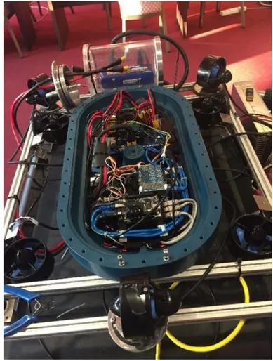
A widely known issue nowadays is the amount of toxic waste in the seas of the world. One of those seas is the Baltic sea. It is estimated that there are several thousand barrels filled with mercury and other toxic wastes at the bottom of the sea near the coast line. In the future, these barrels may have holes in them due to corrosion, allowing toxic waste to leak into the water and contaminate wildlife. Therefore, these harmful materials should be removed as soon as possible. Several attempts have been accomplished to develop an AUV capable of finding these barrels and in the future contain them in a safe manner. Its aim is to autonomously navigate the sea floor and map the areas where it has previously been in, with the assistance of a stereo camera pointing downwards. It maintains a constant height from the floor while navigating and it is able to adapt to changes in the environment, for instance currents. The goal is for it to be able to survey an area of interest and collect data. Figure3 shows the NAIAD.
Figure 4: Communication in the NAIAD.
Figure4presents a schematic diagram of the LINUX based computer ODROID responsible for the main computations, it is where most of the mission planning is executed. It also sends the desired position via ethernet to the Beagle Bone Black (BBB). In its turn, the BBB board receives accelerometer values from an inertial measurement unit (IMU) [23], and sends the current position back to ODROID.
In this thesis, the control unit BBB is replaced by a TIVA Series board TM4C129ENCPDT having the same functionality. The new system should fit in the existing NAIAD architecture and be at least as responsive as the previous system.
Concerning the communication inside the NAIAD, there are two types of communication pro-tocols, UART and I2C. UART [24] is an asynchronous serial communication where data format and transmission speeds can be adjusted. I2C [25] is a synchronous serial computer bus mainly intended for short distance communications within a single device.
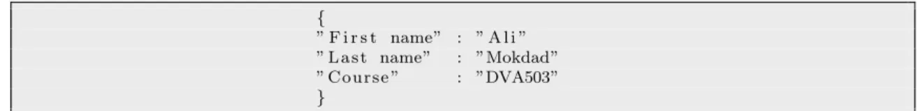
In order to send and receive packages from the LINUX based computer ODROID, a specific format needs to be applied to convert the given data into text data. JavaScript Object Notation (JSON) [26] is a readable format applied to structure data [27]. It specifies data transmission between a server and a specific application. This means that any JavaScript object can be converted into JSON, in order to be sent to the server.
JSON is built on two structures:
• A group of name and value pairs, which can also be defined as an object. • An ordered list of values defined also as an array or a sequence.
The structure of a JSON object is shown in the Listing1, similar to the structure employed in this thesis work.
{
” F i r s t name” : ” A l i ” ” L a s t name” : ”Mokdad” ” C o u r s e ” : ”DVA503” }
Listing 1: JSON Object representation.
Control theory utilizes feedback loops in order to control the system by taking the current value into account to generate new set-point values. Controllers can comprise of one up to three components P, I and D. P represents proportional, I represents integral and D represents derivative. The PID controller is by far one of the most common feedback controllers, known to provide fast transient response and zero steady state error. Today, more than 90 percent of all control loops are PIDs [28]. Figure 5symbolically represents a PID controller in a feedback loop3.
Figure 5: PID controller in a feedback loop
A PID controller continuously calculates an error value e(t) as the difference between a desired set-point and a measured process variable. Then, it delivers a correction as feedback to the input based on the PID terms. After that, it checks if the set-value is achieved. If not, it provides a set-value according to the current input value. The posture control of a robot is necessary since it enables the robot to move in a dynamic environment with stability and precision into the desired locations.
A PID controller is one of the first solutions that should be applied when feedback is exploited [28]. The PID controller handles a wide range of problems: Process control, motor drives, magnetic and optic memories, automotive, flight control and instrumentation [28].
The NAIAD is an already existing project at M¨alardalen University. This project went through several attempts of redesigning the electronics, moving the code to a new platform and writing control algorithms so that the robot could follow a specific path in the water.
In order to allow the NAIAD to move, a specific type of motor controller needs to be implemented. The selected controller is a PID controller.
The NAIAD consists of the following main parts: A brain for decision making, sensors, motors, and a development board. Figure4shows these main parts of the NAIAD.
5
Implementation
The new implementation of the NAIAD is based on the real time operating system FreeRTOS [29], applied on the Tiva Series board. The reason for selecting FreeRTOS is that it is an open source real time operating system and compatible with most of the embedded systems. This implementation covers several major parts: Header files, read IMU sensor data, PID control, and tasks and scheduling. These parts are shown with their relation to the extracted guidelines.
5.1
Header Files
The header files constitute a big part of the implementation during translating the ADA code to C. The reason is that some header files employed in ADA cannot be applied when coding C. Some of the header files have similar headers in C, with almost the same functionality, but others do not. In that case, some header files need to be modified before being included in the project.
For instance, the JSON library with all its header files applied on the BBB did not have the same library provided in C. The JSON library employed for the ported code is JANSSON, it has different function names than the JSON library employed in ADA. That means that all the header files that were included in the code related to JSON, present on the BBB, had to be modified. In addition, this step was not expected in the decision making design, which employs the already existing design. The assumption was that the same JSON library available in ADA would be provided in C, with the same function calls. Not only that, sometimes each header file includes even more header files that need modifications, which made the work consume even more time.
Some may ask why not employ the new library with all its functions and headers already accompanied with it. The reason is that some JSON functions are also called from ODROID, which means that if the function names in the new library change, they should be changed in ODROID too. But, in this thesis, it was not possible to get access to the ODROID’s code from the university. This affected ODROID’s ability to read the data sent from the TIVA series board in the form of JSON packages.
5.2
Read IMU Sensor Data
The communication protocol applied to read IMU sensor values is UART. This communication is performed on a high speed of 115200 bps, since the sensor has very high precision and sensitivity and needs to notify the TIVA board with the latest values as fast as possible. The transmitting and receiving pins of the IMU are connected to the receiving and transmitting pins of the Tiva board respectively.
To transmit the data, the transmitting UART on the IMU sensor switches the transmission line from high to low for one clock cycle. When the receiving UART on the Tiva board detects the high to low voltage transition, it starts reading the bits in the data frame at the baud rate frequency. To signal the end of the data packet, the sending UART drives the data transmission line from a low voltage to a high voltage for at least two bit duration.
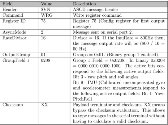
The IMU sensor applied in this thesis is a VN-100. This IMU gives the user the opportunity to select one or more desired output fields that they wish to read. Once the user determines the desired outputs for the output messages, they should configure the User Output Message Configuration Registers (Register 75 77). A more detailed explanation of the registers and the output fields is present in the IMU’s data sheet4. In this case study, the output message consists of x, y, z, roll,
pitch and yaw data. To configure this output message, the following command needs to be sent to the VN-100:
$VNWRG,75,2,16,01,0208*XX
This command consists of the data shown in Table 1, transmitted from the transmitter (Tx) of the Tiva board to the receiver (Rx) of the IMU sensor.
4Source:https://www.vectornav.com/docs/default-source/documentation/vn-100-documentation/
Field Value Description
Header $VN ASCII message header
Command WRG Write register command
Register ID 75 Register 75 (Config register for first output
message)
AsyncMode 2 Message sent on serial port 2.
RateDivisor 16 Divisor = 16. If the ImuRate = 800Hz then,
the message output rate will be (800 / 16 = 50 Hz).
OutputGroup 01 Groups = 0x01. (Binary group 1 enabled)
GroupField 1 0208 Group 1 Field = 0x0208. In binary 0x0208
= 0000 0010 0000 1000. The active bits cor-respond to the following active output fields: Bit 3 - yaw pitch and roll angles.
Bit 9 - IMU (Calibrated uncompensated gyro and accelerometer measurements.)espond to the following active output fields: Bit 1 Yaw-PitchRoll
Checksum XX Payload terminator and checksum. XX means
bypass the checksum evaluation. This allows to type messages in the serial terminal without having to calculate a valid checksum.
Table 1: Configuration of the desired output message
An example of the recived output from the IMU is presented in Table2. This example shows if only the roll, pitch and yaw are being read, for a better understanding of the message format received. The sync byte is the first byte in the header, having a value always equal to 0xFA. The Group parameter identifies the binary output groups from which data will be selected for the output, in this case it is the group that has the roll, pitch and yaw data. The group field parameter consists of one or more 16-bit words per selected output group, employed to identify the output fields selected for that group. The first series of words belong to the fields of the first selected group. After that, a series of word(s) for the next selected group follows. The payload consists of the output data selected in the group byte and the group field bytes, and in this case it is the roll, pitch and yaw data. The CRC is a 16-bit checksum. It is a simple way of checking if the CRC calculation of the entire packet results in zero, proving that the message is received correctly.
Table 2: Serial output message format of IMU sensor
5.3
PID Controller
The launchpad performs the PID control of the NAIAD and has three main parts implemented: Read data from the server ODROID, update PID data, and send signals to the thrusters.
the NAIAD. These commands sent from ODROID are in the form of a JSON package, consisting of x, y and z, roll, pitch and yaw data. These values are handled as inputs of the PID controller. As discussed previously in Section 5.1, the Tiva series board needs to call a JSON function to unpack the received package from ODROID. This constituted a problem in terms of receiving new input data for the PID controller.
In the step of updating the PID data, the system consisting of the parameters P, I and D as shown in Figure 5 estimates initial values to tune pulse width modulation (PWM) signals sent to the NAIAD’s thrusters. The resulting coordinates of the NAIAD’s position are sent back to ODROID and compared to the originally desired coordinates. This produces an error which is sent again to the Tiva board to update the P, I and D values. This process happens over and over to reach more precise P, I and D values performing the intended movements of the NAIAD.
Since this PID process has already been performed on the previous BBB board, the first test was to try the already obtained P, I and D values of the old system. The reason for that is that the P, I and D values of the previous system were working as intended. The next step in case these values would not perform as intended on the new system, was to re-perform the P, I and D control to obtain their new values instead of applying their already available values from the previous NAIAD. This concept is presented in Listing2.
// I n f i n i t e l o o p w h i l e( 1 ) { // Get t h e c u r r e n t p o s i t i o n c u r r e n t p o s i t i o n = r e a d c u r r e n t p o s i t i o n ( ) ; // C a l c u l a t e t h e e r r o r e r r o r = t a r g e t p o s i t i o n − c u r r e n t p o s i t i o n ; // C a l c u l a t e t h e i n t e g r a l i n t e g r a l = i n t e g r a l + e r r o r ; // C a l c u l a t e t h e d e r i v a t i v e d e r i v a t i v e = e r r o r − l a s t e r r o r ; // C a l c u l a t e t h e c o n t r o l v a r i a b l e pwm = (Kp ∗ e r r o r ) + ( Ki ∗ i n t e g r a l ) + (Kd ∗ d e r i v a t i v e ) ; // L i m i t t h e c o n t r o l v a r i a b l e t o w i t h i n +−255 i f (pwm > 2 5 5 ) pwm = 2 5 5 ; e l s e i f (pwm < −255) pwm = −255; // I f c o n t r o l v a r i a b l e i s p o s i t i v e , run t h e motor c l o c k w i s e i f (pwm > 0 ) motor cw (pwm ) ; // I f c o n t r o l v a r i a b l e i s n e g a t i v e , run t h e motor c o u n t e r c l o c k w i s e e l s e i f (pwm < 0 ) motor ccw (pwm ) ; // i f t h e c o n t r o l v a r i a b l e i s Zero , s t o p t h e motor e l s e m o t o r s t o p ( ) ; // Save t h e c u r r e n t e r r o r a s t h e l a s t e r r o r f o r t h e n e x t i t e r a t i o n l a s t e r r o r = e r r o r ; }
Listing 2: Concept of the PID controller’s implementation
The last step of maneuvering to the desired position, is performed by controlling all the six motors of the NAIAD by sending PWM signals to the motor controllers attached to them. There are two ways to enable pins for the Tiva Board. The first is to change the bits of the hardware registers within the microcontroller directly. The second method uses the installed libraries by enabling the functionality for the microcontroller within the specific integrated development environment, in our case in the IDE of the tiva board. The second method is applied in this case study in order to make the process easier on the user instead of enabling pins and hardware functions. At the same time, it would be a good test on the Tiva board with its installed libraries.
In that case, the Listings3and4show which header files are applied to the PWM and how its functionality is enabled and configured respectively.
#i n c l u d e ” i n c /hw memmap . h” #i n c l u d e ” i n c / h w g p i o . h” #i n c l u d e ” d r i v e r l i b / g p i o . h” #i n c l u d e ” d r i v e r l i b / pin map . h” #i n c l u d e ” d r i v e r l i b /pwm. h” #i n c l u d e ” d r i v e r l i b / s y s c t l . h”
Listing 3: Header files included for PWM
S y s C t l P e r i p h e r a l E n a b l e ( SYSCTL PERIPH GPIOF ) ; S y s C t l P e r i p h e r a l E n a b l e (SYSCTL PERIPH PWM1 ) ; SysCtlPWMClockSet (SYSCTL PWMDIV 1)
HWREG(GPIO PORTF BASE + GPIO O LOCK) = GPIO LOCK KEY ; HWREG(GPIO PORTF BASE + GPIO O CR ) |= 0 x01 ;
GPIOPinConfigure (GPIO PF0 M1PWM4 ) ; GPIOPinConfigure (GPIO PF1 M1PWM5 ) ; GPIOPinConfigure (GPIO PF2 M1PWM6 ) ; GPIOPinConfigure (GPIO PF3 M1PWM7 ) ;
GPIOPinTypePWM(GPIO PORTF BASE , GPIO PIN 0 | GPIO PIN 1 | GPIO PIN 2 | GPIO PIN 3 ) ;
PWMGenConfigure (PWM1 BASE, PWM GEN 2, PWM GEN MODE DOWN | PWM GEN MODE NO SYNC ) ;
PWMGenConfigure (PWM1 BASE, PWM GEN 3, PWM GEN MODE DOWN | PWM GEN MODE NO SYNC ) ;
PWMGenPeriodSet (PWM1 BASE, PWM GEN 2, 4 0 0 ) ; PWMGenPeriodSet (PWM1 BASE, PWM GEN 3, 4 0 0 ) ; PWMPulseWidthSet (PWM1 BASE, PWM OUT 4, 3 0 0 ) ; PWMPulseWidthSet (PWM1 BASE, PWM OUT 5, 3 0 0 ) ; PWMPulseWidthSet (PWM1 BASE, PWM OUT 6, 3 0 0 ) ; PWMPulseWidthSet (PWM1 BASE, PWM OUT 7, 3 0 0 ) ; PWMGenEnable (PWM1 BASE, PWM GEN 2 ) ;
PWMGenEnable (PWM1 BASE, PWM GEN 3 ) ;
PWMOutputState (PWM1 BASE, (PWM OUT 4 BIT | PWM OUT 5 BIT | PWM OUT 6 BIT | PWM OUT 7 BIT ) , t r u e ) ;
Listing 4: Enabling the functions within the PWM program
5.4
Tasks and Scheduling
This section presents the tasks employed on the new Tiva series board, and how they are sched-uled. Scheduling is the activity of organizing the execution order of tasks based on their priorities, periods, execution times and deadlines. This activity is necessary for tasks to meet their real-time requirements. Five tasks are created in the implementation, and they are executed depending on their priorities, meaning that the task with the higher priority executes first. The reason for assigning these priorities is that each task might require input from a previously occurring task. For instance, depending on the input, the PID controller reacts and provides specific outputs. The created tasks are shown in the Listing5, with their corresponding priorities from one to five respectively:
// T h i s t a s k r e a d s d a t a from t h e s e r v e r ODROID.
x T a s k C r e a t e ( P i d R e a d F r o m S e r v e r , ” Task 1 ” , 1 0 2 4 , NULL, 1 , NULL ) ;
x T a s k C r e a t e ( r e q u e s t c a l c , ” Task 2 ” , 1 0 2 4 , NULL, 2 , NULL ) ;
// T h i s t a s k r e a d s IMU s e n s o r d a t a .
x T a s k C r e a t e ( Read imu , ” Task 3 ” , 1 0 2 4 , NULL, 3 , NULL ) ;
// T h i s t a s k u p d a t e s t h e PID d a t a .
x T a s k C r e a t e ( Update PID Data , ” Task 4 ” , 1 0 2 4 , NULL, 4 , NULL ) ;
// T h i s t a s k c o n t r o l s t h e m o t o r s t o move t o a d e s i r e d p o s i t i o n and o r i e n t a t i o n .
x T a s k C r e a t e ( G o T o D e s i r e d P o s i t i o n A n d O r i e n t a t i o n , ” Task 5 ” , 1 0 2 4 , NULL, 5 , NULL ) ;
6
Extracted Guidelines
The guidelines resulting from the research papers presented in Section 3 are listed below, and accompanied with a description of how they are applied in the case study.
1. Evaluate Requirements Through Decision Making Support. In the case study, no redesign was necessary. The design is presented in Figure 4, which is the already existing one of the NAIAD. The reason for selecting the already existing design is that the code that needs to be ported into the new Tiva series board constitutes only a part of the NAIAD project. An additional reason is that the previous design works fine, so there is no need to select a different design for the new system.
2. Identify Hardware-Elements Without Software Support. In the NAIAD, the hard-ware and the OS need to be changed. The BBB board was replaced with the Tiva series board. In addition to that, the Robot Operating System (ROS) had to be changed to FreeRtos due to the lack of some device drivers and because of the time limit. Due to this change, some communication protocols have been affected. There is an existing Ethernet communication protocol in the old system which is not compliant with the new system. But there is a different solution for the new system which is UART. This lead to a switch of the communication protocol from ethernet to UART.
3. Identify Source-Code To Be Modified. This includes all the source code present on the BBB board, including PID source code, since the BBB is the only hardware that needs to be replaced by the new development board. This step also includes header files related to PID, UART and JSON.
4. Identify Source-Code Relationships. In the case study, the relationships of the source code include: IMU source-code, PID source-code, JSON and communication source-code. This work is needed for gathering the information related to dependency of a source-code which is a read-and-search job inside the operating system source-codes.
5. Identify Source-Code Precedence. This step is similar to scheduling, since each source-code has a specific priority to start with. The precedence of source source-code applied in the thesis is designed as follows:
(a) IMU source-code, (b) PID source-code, and
(c) Communication source code.
This precedence is selected since each source code is related to the previous one that needs to be present first.
7
Discussion And Limitations
The translation of the code from ADA working on the BBB board into C language working on the Tiva series board proved to be challenging concerning the libraries applied in the ADA code. The difference in libraries slowed the translation process down. The reason is that extra time has been spent on writing header files and editing others, to suit the already existing components of the NAIAD.
In addition, the JSON library, which is proven to work on the Tiva series board, is different than the one employed in ODROID. So the data obtained from the IMU sensor is not sent suc-cessfully to the ODROID in the form of a package of a JSON object. This constitutes a problem of calling the function that unpacks the JSON object sent from the Tiva series board to ODROID that has the current position of the NAIAD. As a result of that, the communication between the Tiva series board and ODROID would be paralyzed. All the other parts of the implementation including the PID control seem to work as intended, but are not fully tested on the NAIAD, since there has been a problem in notifying ODROID with the current position.
The challenge in this thesis has been in trying to fit the new development board into the al-ready existing system. The reason for that is the incapability of modifying the ODROID part of the NAIAD provided by the university which could not be altered to influence the performance of the system. An additional reason is that NAIAD is a big project where ODROID works as intended for the ADA code of the BBB board. That means that modifying ODROID may dam-age the already working NAIAD coupled with the BBB board. The resulting performance tests was not fully tested on the NAIAD due to the lack of time, and the lack of an environment to place the NAIAD underwater and perform the tests. Despite facing some challenges in the thesis, the advantage of the new PID controller is clear, since the new PID is implemented in C language which is theoretically faster than ADA [30]. In addition, the new hardware is supposed to be faster. The research question RQ.1 was whether there are any guidelines for porting embedded systems software, and it is presented in the literature study being performed over guidelines for code porting. The research question RQ.2 was if these guidelines could be applied when porting code from ADA to C, and if they are successful. In the scope of this thesis, this question could not be fully answered because the time was too short and the task was challenging. Although the estimate answer would be that it is successful, since the literature study shows that. But the experiment could not actually be performed due to time constraints. The research question RQ.3 was about the best practices or strategies that could be employed if there are no guidelines. This question has been answered as a future work due to time constraints. It is presented in Section3.1where some tools would be applied in case code porting performed in the thesis does not meet the intended results.
8
Conclusion And Future Work
This thesis provides the fundamental discussion of code porting and its general guidelines, while porting code. Beyond that, this thesis improves the PID controller for the NAIAD. During the development of the thesis, the students expand their knowledge on code porting in embedded sys-tems. In particular, this thesis contributes to the state of the art regarding real time systems being time triggered, and better understanding of the different communications employed in the NAIAD. This thesis also provides an initial comparative literature study on PIDs employed on different target platforms. This is one of the research areas that is too large to be discussed in the scope of just a master thesis, so some future work could contribute to further expand the state of the art.
A suggestion of future work would be to design a new NAIAD based on several Tiva series boards. It would be interesting to test how they can handle real time constraints. Even more if the aim is to have all the processors on one board, test how that affects the responsiveness of the whole system having just the local scheduler.
Performing code porting always needs a specific approach. Otherwise it may lead to unstable or incomplete projects. The proposed guidelines and finding dependencies between source-codes comprising the operating system ensures that all adjustments are taken into account. As future work, the tools described in the publication[1] could be applied to reach a better and more efficient result of code porting of the NAIAD. This could lead to a general conclusion to be taken into account when performing any type of code porting between two target platforms.
References
[1] S. K˚agstr¨om, “Tools, techniques, and trade-offs when porting large software systems to new environments,” 2008.
[2] O. D. Souza and H. S. Castro, “A complete method for porting operating system for embedded systems,” Real-Time Systems, no. July 2014, pp. 21–28, 2001.
[3] R. Hashemi and R. J. Leach, “Issues in porting software from c to c++,” Software: Practice and Experience, vol. 22, no. 7, pp. 599–602.
[4] B. R. Cravotta and T. Editor, “Successful software porting demands the same engineering discipline as any development pro- fear and loathing,” 2002.
[5] J. P. Pennell, “An assessment of software portability and reusability for the WAM program,” Institute for defense analysis, no. 90, 1990.
[6] E. T. Matthew A. Brown, “Mock Object Patterns ,” 5/19/2003. [7] J. G. Skazinski, “Porting Ada :,” pp. 58–64, 1994.
[8] N.-Y. Lee and C. R. Litecky, “An empirical study of software reuse with special attention to Ada,” Software Engineering, IEEE Transactions on, vol. 23, no. 9, pp. 537–549, 1997. [9] S. Khan, S. Javed, N. Naeem, and I. Ali, “Performance analysis of pid and state-feedback
controller on the depth control of a robotic fish,” in 2017 International Conference on Frontiers of Information Technology (FIT), Dec 2017, pp. 7–11.
[10] P. S. Bhopale, P. K. Bajaria, F. S. Kazi, and N. M. Singh, “LMI Based Depth Control for Autonomous Underwater Vehicle,” pp. 477–481, 2016.
[11] A. D. Mici´c and M. R. Matau˘sek, “Optimization of pid controller with higher-order noise filter,” Journal of Process Control, vol. 24, no. 5, pp. 694 – 700, 2014.
[12] K. Shimizu, “Optimization of parameter matrix : optimal output feedback control and optimal PID control,” no. 3, 2017.
[13] K. H. Ang, G. Chong, and Y. Li, “PID control system analysis, design, and technology,” IEEE Transactions on Control Systems Technology, vol. 13, no. 4, pp. 559–576, 2005. [14] O. Garpinger, T. H¨agglund, and K. J. ˚Astr˝om, “Performance and robustness trade-offs in pid
control,” Journal of Process Control, vol. 24, no. 5, pp. 568 – 577, 2014.
[15] V. R. Segovia, T. H¨agglund, and K. ˚Astr˝om, “Measurement noise filtering for pid controllers,” Journal of Process Control, vol. 24, no. 4, pp. 299 – 313, 2014.
[16] S. Alc´antara, R. Vilanova, and C. Pedret, “Pid control in terms of robustness/performance and servo/regulator trade-offs: A unifying approach to balanced autotuning,” Journal of Process Control, vol. 23, no. 4, pp. 527 – 542, 2013.
[17] I. I. Farkas, A. Tulbure, and C. Farcas, “Advanced control procedure for autonomous underwa-ter robots,” Proceedings of the 2015 7th Inunderwa-ternational Conference on Electronics, Compuunderwa-ters and Artificial Intelligence, ECAI 2015, pp. P95–P100, 2015.
[18] C.-L. Kuo, C.-K. Tsui, N.-S. Pai, C.-H. Lin, S.-C. Chen, and P.-W. Li, “A PID Controller for the Underwater Robot,” pp. 1242–1246, 2016.
[19] T. Ariyachartphadungkit, R. Vanijjirattikhan, and S. Hasegawa, “Implementation of PID posture controller for 6 DOF underwater robot,” International Conference on Electronics, Information, and Communications, ICEIC 2016, pp. 2–5, 2016.
[20] A. Z. Abidin, R. Mardiyanto, and D. Purwanto, “Implementation of PID controller for hold altitude control in underwater remotely operated vehicle,” Proceeding - 2016 International Seminar on Intelligent Technology and Its Application, ISITIA 2016: Recent Trends in Intel-ligent Computational Technologies for Sustainable Energy, vol. 20, pp. 665–670, 2017. [21] M.-T. H. M.-T. Ho, A. Datta, and S. Bhattacharyya, “A linear programming characterization
of all stabilizing PID\ncontrollers,” Proceedings of the 1997 American Control Conference (Cat. No.97CH36041), vol. 6, no. June, pp. 3922–3928, 1997.
[22] J. L. C. Rolle, R. F. Garc´ıa, H. L. Garc´ıa, and I. M. Gonz´alez, “Developed an expert system of an empirical method to choose correct expressions for pid controllers tuning in open loop,” in 2009 35th Annual Conference of IEEE Industrial Electronics, Nov 2009, pp. 2044–2049. [23] N. Ahmad, R. A. R. Ghazilla, N. M. Khairi, and V. Kasi, “Reviews on Various Inertial
Measurement Unit (IMU) Sensor Applications,” International Journal of Signal Processing Systems, vol. 1, no. 2, pp. 256–262, 2013.
[24] Y. Y. Fang and X. J. Chen, “Design and simulation of UART serial communication module based on VHDL,” 2011 3rd International Workshop on Intelligent Systems and Applications, ISA 2011 - Proceedings, vol. 1, 2011.
[25] V. K. Pandey, “A review paper on I2C communication protocol,” vol. 4, no. 2, pp. 340–343. [26] M. Taylor, Introduction to JavaScript Object Notation: A To-the-point Guide to JSON. USA:
CreateSpace Independent Publishing Platform, 2014.
[27] C. Severance, “Discovering javascript object notation,” Computer, vol. 45, no. 4, pp. 6–8, April 2012.
[28] K. ˚Astr¨om and T. H¨agglund, “The future of pid control,” Control Engineering Practice, vol. 9, no. 11, pp. 1163 – 1175, 2001, pID Control.
[29] Richard Barry, “Mastering the FreeRTOS Real Time Kernel, A Hands-On Tutorial Guide,” p. 398, 2016.
![Figure 2: Conceptual model of empiric adjustment of PID regulators [22].](https://thumb-eu.123doks.com/thumbv2/5dokorg/4828767.130248/10.892.242.654.313.555/figure-conceptual-model-of-empiric-adjustment-pid-regulators.webp)