TPC Components AB
School of Innovation, Design and Engineering
Optimization of sprue design for advanced
investment casting through FEA analysis
Bachelor thesis work Basic level, 15 points Product and Process Development
Kanthee Prathan
Mälardalens University, Academy for Innovation, Design and Engineering Supervisor, TPC AB: Daniel Kuivamäki
Supervisor, university: Barrett Sauter Examinor: Janne Carlsson
ABSTRACT
Investment casting is a complex manufacturing method with many challenges that must be solved before components of the right quality can be produced.
TPC is a company that utilizes investment casting to produce a variety of products, lately the company has higher ambition in wanting to cast higher technical demanding component like heat resistant gas turbine blades. This requires a sprue that can control the filling process, by allowing the fallen stream of molten metal to enter the moulds cavity in a laminar manner. This study has implemented the product development process by (Ulrich, 2012) to develop the requested sprue. The primary support for this study is study material given by the company also known as "PMG running spreadsheet TPC" base on theory and equations from (Jolly, 2002), which is believed to have origin in sand casting manufacturing process.
The project began with recreating the textbook model after establishing a number of control parameter such as critical velocity. Then simulation software Nova flow was used to evaluate the velocity and FEM in Solidworks to study if the dimension of the model can be directly use for investment casting process. The results show that it was not possible, therefore in the concept generating phase only theory of casting was used to create new concept. Then 3 existing sprues were chosen for benchmarking to gain deeper understanding about their design intension. One of the concepts was inspired by the CEO Mark Irwin “concentric pipe design” and in total 10 concepts were created of which 6 were tested for both flow and FEM analysis. 2 concepts were chosen for further development which also became 2 final concepts, after 3 iterations of improvement.
These concepts show that many improve in terms of laminar filling and higher yield than the existing benchmark sprues. Although further development is required.
The analysis shows that every step in the project has its own flaws, but that is the nature of being an engineer, as long as the problem encountered can be viewed with critical and
analytical eyes. A well-considered and balanced solution can be provided, although nothing of this can be certain before a trail of test can provided to confirm any assumptions which is not included in this work.
The discussion section processes the thoughts, experience, and doubts about the project in general and the decision making leading to this report and what could have been done differently. The most significant lesson learn from this is that section is when solving a complex issue there must be very clear delimitations and well-defined goals to every specific solution. Otherwise the workload will be extensive and cause more harm than necessary. The conclusion of this project shows that two concepts generated with the help from the product development process work better than the case study, which can be found in section 4.3, that was based on “PMG running spreadsheet TPC” calculation model, from the velocity perspective. To achieve this, the sprue uses its own geometry constrain and constricts the flow by collecting the molten metal in a “well” before the calmer stream could be distributed throughout the whole cavity. Indirectly this means that the studied material given from TPC AB could not be directly implemented into the investment production process. The given material should be seen as a complement and guidance when creating new sprues.
Concerning the FEM analysis tool, it was helpful in this project in evaluating the sprues geometry expose to the assumed force in the production process to avoid unnecessary failure and therefore waste. Although if the company do not intend further work with the development of other sprues then this method is not necessary and would not have significant value to their current manufacturing process.
ACKNOWLEGEMENT
I would like to thank everyone, friends and family who supported me in this project during this last few month and who showed great understanding for my absence from all the important events.
Many thanks and appreciation to my supervisor(s) in helping me to understand the many issues in this work so that appropriate solutions could be provided. Also, great thanks to TPC AB, especially Mark Irwin for giving me the opportunity to conduct this study and to learn so much about their process and the casting industry. This have been a great lesson-learn journey
without them this would not have been possible.
Special thanks to my better half who has been supportive in both time and effort by reading this report countless times and correcting my mistakes. Without her this study would not have been possible.
CONTENTS
1. INTRODUCTION ... 10
1.1. BACKGROUND ... 10
1.2. PROBLEM FORMULATION ... 10
1.3. PURPOSE AND RESEARCH QUESTIONS... 12
1.4. DELIMITATION ... 12
2. METHODOLOGY ... 13
2.1. PRODUCT DEVELOPMENT PROCESS ... 13
2.1.1. PLANNING ... 13 2.1.2. CONCEPT DEVELOPMENT ... 13 2.2. INFORMATION GATHERING... 15 2.2.1. LITERATURE STUDY ... 15 2.2.2. OBSERVATION ... 15 2.2.3. CONFERENCE CALL ... 16 2.2.4. DISCUSSION ... 16 2.2.5. CASE STUDY ... 16 2.2.6. BENCHMARK ... 16 2.2.7. FEM ANALYSIS ... 17 2.2.8. SOFTWARE ... 17 2.3. 3D-PRINTING ... 17 3. THEORETICAL FRAMEWORK ... 18 3.1. WHAT IS CASTING? ... 18 3.2. INVESTMENT CASTING ... 18 3.3. SAND CASTING ... 19 3.4. CASTING RULES ... 20 3.5. GATING SYSTEM ... 21 3.6. LAMINAR FLOW ... 22 3.7. COMPANY ANALYSIS ... 23 3.7.1. THE CASTING PROCESSES ... 24
3.7.2. CONCENTRIC PIPE DESIGN ... 24
4. EMPIRICS ... 25
4.1. OBSERVATION ... 25
4.1.1. COMPANY PRODUCTION PROCESS ... 25
4.1.2. DISCUSSION ... 27 4.1.3. CONFERENCE CALL ... 27 4.2. DESIGN STRATEGY ... 27 4.3. CASE STUDY ... 30 4.4. BENCHMARK ... 33 4.5. CONCEPTS DEVELOPMENT ... 37
4.5.1. IDENTIFY THE CUSTOMERS NEED ... 38
4.5.2. ESTABLISHED TARGET SPECIFICATIONS ... 38
4.5.3. CONCEPT GENERATING ... 38
4.5.4. CONCEPT SELECTION ... 55
4.5.5. TEST PRODUCT CONCEPTS ... 55
5. RESULTS ... 71 5.1. CONCEPT4.3 ... 71 5.2. CONCEPT6.2 ... 72 6. ANALYSIS ... 74 6.1. DESIGN STRATEGY ... 74 6.2. CASE STUDY ... 74 6.3. BENCHMARK ... 74 6.4. T ... 75
6.5. RESULTS ... 77 6.6. RESEARCH QUESTIONS ... 78 7. DISCUSSION ... 80 8. CONCLUSION ... 81 9. RECOMMENDATION ... 81 10. REFERENCES ... 82 11. APPENDIX ... 83
List of Figure
Figure 1, Product development process. ... 13
Figure 2, the frontprocess and what activity this process includes. ... 14
Figure 3, the phenomena of vena contracta in (a) and how the flow behave if the down sprue are cynlindrical in (b) and the shaping of the downsprue to utilize the natural shape in (c) (Jolly, 2002). ... 22
Figure 4, the actual casting process. ... 24
Figure 5, the observation of the actual investment casting process at the company. ... 25
Figure 6, test piece, the left figure is without and on the right with the standard ingate. ... 28
Figure 7,the two halves of a sand casting mould. ... 30
Figure 8, the results from the flow simulation, shows the filling sequence of 10% - 90%. ... 31
Figure 9, FEA analysis used to evaluate the dimension. ... 31
Figure 10, benchmark sprue no.1, the left side is the actual footage and the right is a recreated 3d-model. ... 33
Figure 11, benchmark sprue no.2, the left side is the actual footage and the right is a recreated 3d-model. ... 34
Figure 12, benchmark sprue no.3, the left side is the actual footage, the middle sprue is the original design and the right is a recreated 3d-model. ... 35
Figure 13, how mounting can be solved in a one level solution. ... 37
Figure 14, concept A. ... 40 Figure 15, concept B. ... 41 Figure 16, concept C. ... 42 Figure 17, concept D. ... 43 Figure 18, concept E. ... 44 Figure 19, concept F. ... 45 Figure 20, concept G. ... 46 Figure 21, concept H. ... 47 Figure 22, concept I. ... 48 Figure 23, concept J. ... 49 Figure 24, concept4.1. ... 50
Figure 25, concept6.1 shows the same runner design as concept4.1 in the right figure. ... 51
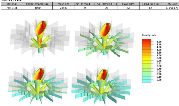
Figure 26, concept4.2. ... 52
Figure 27, concept4.3, where runners are being redesign, angle lowered, and the "skirt" are being introduce to this version ... 53
Figure 28, final concept6.3 ... 54
Figure 29, concept1 flow simulation. ... 57
Figure 30, FEA simulation of concept1. ... 58
Figure 31, concept2 flow simulation. ... 58
Figure 32, FEA simulation of concept2. ... 59
Figure 33, concept3 flow simulation. ... 59
Figure 34, FEA simulation of concept3. ... 60
Figure 35, concept4 flow simulation. ... 61
Figure 36, FEA simulation of concept4. ... 62
Figure 37, concept5 flow simulation. ... 62
Figure 38, FEA simulation of concept5. ... 63
Figure 39, concept6 flow simulation. ... 64
Figure 40, FEA simulation of concept6. ... 64
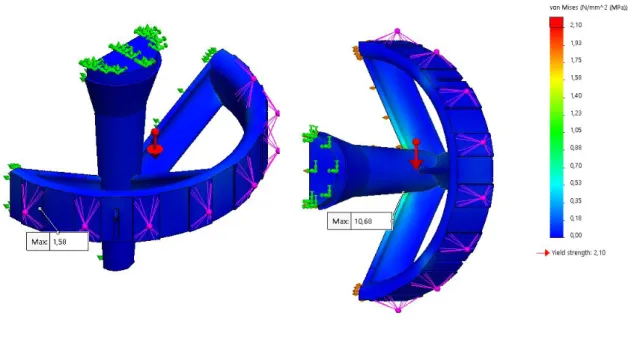
Figure 42, FEA simulation of concept4.2. ... 66
Figure 43, concept6.1 flow simulation. ... 66
Figure 44, FEA simulation of concept6.1. ... 67
Figure 45, flow simulation of concept4.3. ... 68
Figure 46, FEA simulation of concept4.3. ... 68
Figure 47, flow simulation of concept6.2. ... 69
Figure 48, FEA simulation of concept6.2. ... 70
Figure 49, concept4.3 the left picture shows the isometric view and the right view is cross sectional view ... 71
Figure 50, the left picture shows concept4.3 from top view and right picture shows the sprue from below ... 72
Figure 51, concept6.2 the right picture shows the isometric view and the right is a cross.sectional view ... 73
Figure 52, concept6.2 the left picture shows concept6.2 the sprue from above and the right shows the sprue from below. ... 73
List of tables
Table 1, parameters on the standardized testing piece. ... 29
Table 2. properties of benchmark sprue no. 1. ... 34
Table 3, properties of benchmark sprue no. 2. ... 35
Table 4, properties of benchmark sprue no. 3. ... 36
Table 5, findings from analysing the chosen sprues. ... 36
Table 6, the identify needs from the company. ... 38
Table 7, the established target specifications. ... 38
Table 8, properties of concept A. ... 40
Table 9, properties of concept B. ... 41
Table 10, properties of concept C. ... 42
Table 11, properties of concept D. ... 43
Table 12, properties of concept E. ... 44
Table 13, properties of concept F. ... 45
Table 14, properties of concept G. ... 46
Table 15, properties of concept H. ... 47
Table 16, properties of concept I. ... 48
Table 17, properties of concept J. ... 49
Table 18, properties of concept4.1 ... 50
Table 19, properties of concept6.1. ... 51
Table 20, properties of concept4.2. ... 52
Table 21, properties of final concept4.3. ... 53
Table 22, propertis of final concept6.3. ... 54
Table 23, the scoring matrix. ... 55
Table 24, material propertys data. ... 56
Table 25, the comparing results of concept4.3 against benchmark sprues ... 72
Abbreviation
FEM Finite Element Method
FEA Finite Element Analysis
1. INTRODUCTION
The process of casting can be dated to a prehistoric time and has been developed ever since. What was known as lost-wax process is today Investment casting. Investment casting is responsible for the production of most of today’s compressor blades for gas turbines for instance in airplanes. Although, this manufacturing process has for long been look down upon, due to its reputation of being low cost and unreliable in a bad context.
The casting is a complex manufacturing process which is influenced by very many factors, is very challenging to control them all and is therefore considered unreliable.
This issue can be tackled by performing advanced study using simulation software and product development method and by that predicting potential problems in the manufacturing of high-end components. (Jolly, 2002, pp. 2-4)
This study aims to design new sprue by concentrates on the defect from surface turbulence, more specific the velocity during the filling phase of the investment casting at the company TPC AB.
1.1. Background
TPC Components AB is a foundry company that specializes in precision casting, located in Hallstahammar. The company has a long-established tradition in the mass production industry making and casting products for all kind of industries. These products were defined as industry components, meaning they had less or non-existing requirements. The financial crises 2008 had a great impact on the company, the demand for casting product the company produced had reduced to a level where it had threatened the company’s survival. The circumstances forced the company to search for new markets where it could secure its future. The answer was, premium products which are products with higher specification requirements, which also requires more refined technical development than before. For instance, to be able to cast these high-end products, like a heat resisting blade in an industrial gas turbine the filling of the moulds must be more controlled. (Irwin, 2020)
1.2. Problem formulation
A common problem in foundry is porosity or impurities in the casting’s details.
The biggest challenges with investment casting as a manufacturing process is to limit the number of defects, the type of defects and its extent to avoid deteriorate mechanical properties in the components. To be able to minimize the defect rates is utmost important, this is
especially critical for casting of thin walled structures with complex geometry like lightweight structures component for aircraft engines or components used in industrial gas turbine. The definition of complex geometry in this context is parts with asymmetric cross section, a very clear example for this is a turbine blade which consists of both thick and thin wall sections and in some more advanced blades build-in cooling channels can also be found.
Many of the existing ingate systems were inherited from a well-established industrial era, which had other priorities like mass production with lower requirements to non-existing on the castings parts. This means that many of these ingate systems are designed to be used to cast components with higher standard in terms of quality and mechanical properties, so called premium parts. These are made in smaller volume with higher price per units and the
explanation for the price tag is not only the complexity on the manufacturing parts, but also the material. Often the parts are made with special metal alloy that can withstand heat and pressure
which other material cannot. To reduce material usage in the manufacturing process means cost-efficiency, that is why it is important to restrict material usage during casting, one way to do this is sizing the ingate system proportion the casting component. Though one of the biggest challenges of using less material can be structural failure during the casting process, to
overcome this issue this thesis will present a well-established method that has not yet been implemented at the foundry and this is FEA.
In short, casting defects and overly use material present many challenging problems for manufacturers in terms of waste in both time and resources. One possible way in reducing the waste is to limit the defects in the castings, by constructing a sprue that can met the
requirement of laminarity and use only necessary material to produce the components by optimizing the sprue using an well-known analysis tools. This is needed, in order to face the global climate challenges and with it, the technical change, every manufacturer must evolve and develop each step of their process to achieve higher efficiency and become stronger competitor in their field of operation, the risk of doing nothing mean to be left behind in a world of obsolete process.
1.3. Purpose and Research questions
This projects goal is to develop a new sprue concept(s) design for investment casting, which aims to lower material usage and defect rate in the casting process. The new design will be based on material provided by the company through a partnership with Cranfield University in Great Britain. Studying these given materials will result in an understanding and hopefully an implementation can be made to suit the company’s existing production process.
Research questions
1. To what extend can the material that is provided by the company be implemented to achieve a concept of laminar filling sprue?
2. How much better are the new concept compared to the benchmark sprues, from the perspective of design and yielding?
3. Can material usage be lower if FEM is implemented during the product development phase?
1.4. Delimitation
The project covers only the design aspect of the sprue and how construction of such can be made to achieve parameters of laminar filling and obtain high yields for a high-end product. Also, to construct the sprue to withstand and survive the investment casting process at the TPC AB where this thesis was conducted. Therefore, parameters such as how solidification and the casting results will not be processed in this thesis. The timeframe for this project is 3 months and this corresponds to a bachelor’s degree.
Subject as economy and thermodynamics are important in casting, thou to include these subjects in this project will be too time consuming, therefore this will be excluded. Although, this cannot be done consequently because the nature of the casting circulates a lot around these subjects, therefore in parts of the report some of these issues may be mentioned, but only to give the reader context. But no theory or deeper explanation will be given, this must be considered as a further work.
In this thesis the product development process will be applied to develop the ingate system, to the extends that is possible therefore some deviation may occur. The project extends only to the
Concept development phase in the Product development process, even here some deviation will
occur, to be specific, the economic analysis will not be performed because it is considered to solve this issue indirect, by trying to optimize the weight and volume in material usage during the construction of the sprues.
In the concept development phase, the project aims to reach all the way to actual testing of the concept at the company. Although, if the time does not allow this then the practical testing will be excluded and only theoretically testing will be includes, meaning simulation results only. If the time allows the practical testing, only two concepts will be chosen, regardless how good or bad the other simulations are. This is because the 3d printing are time consuming, to ensure that it is possible to deliver physical results in time this decision is necessary.
The finite element analysis in this project does not include the force from the ceramic slurry, fluidizing sand bed nor the ceramic shells weight. Due to measurement difficulty to make it reflect actual circumstances- Therefore, to avoid false or misleading result, the thesis chooses not to include these parameters. To cope with this problem during the calculation the
2. METHODOLOGY
This chapter describes the methodology that was used and how information concerning the study was gathered.
The structure of this chapter begins with going through the generic Product development
process written be Karl T. Ulrich Steven D.Eppinger, followed by Information Gathering.
2.1. Product development process
The ability to identify customers' needs and be able to satisfy them, through products or services and at the same time have a competitive price is the foundation and prerequisite for any successful company.
For that reason, it is important to have a process that contributes to achieving that. The product development process consists of several steps for everyone involved in the organization to complete, to work in a systematic way during development process of any goods and services. It creates security for those who work within the chain, to avoid forgetting or ignore important details that is needed if the company are to successfully deliver products and services that truly satisfy customer’s needs. (Ulrich, 2012, pp. 29-30)
Figure 1, illustrates the flow chart of the product development process, that will be implemented during the project.
Figure 1, Product development process.
2.1.1. Planning
The planning phase is also known as “phase 0” this implies that this activity happens before the project has been approved and the actual product development process. This planning stage starts with identifying opportunities within the company strategy, includes the evaluation of the technical development and market goals.
The results of this stage are mission statements which comprise of market targets, business goal, assumption, and limitations. (Ulrich, 2012, p. 44)
2.1.2. Concept Development
The concept development phase starts with identifying the needs that reflect the target market, from which alternative product concept can be generated. These concept needs to be evaluated which is also done at this stage and after the evaluation is done the concept or concepts will be chosen for further development and testing. A concept can be described as a description of a product which contains form, function and features which is motivated by predetermined specifications, studying the competitors by benchmarking and economic perspective of the project.
This phase can also be called frontprocess or front-end process, and contains sub activity that interact with each other and can be seen in Figure 2
Figure 2, the frontprocess and what activity this process includes.
Identify Customer Needs
The task and goal of this activity is to establish an understanding of the customer’s needs and be able to forward this to the development team as effectively as possible. The product of this stage is information about the customer’s needs, carefully picked and place in priority order relative to the importance of the needs.
Establish Target Specifications
The specification should give precise information about what the product should be able to perform. This is done by converting and translating the customer needs into quantifiable terms. The criteria of specifications are decided in an early stage in the process, these also reflect the development team expectations on the outcome. These specifications are later updated, to align with the limitations that has been established in the product concept chosen by the development team. The results of this stage are a list of target specifications which are quantifiable product properties with both marginal and ideal values.
Generate Products Concepts
The goal of this stage is to find all the possible solutions and generate concepts accordingly to satisfy the customer’s needs. The generating of concepts comprises of many approaches that can also be mixed to achieve the best possible solution. The product of this stage is a portfolio of 10 to 20 concepts that is usually produced by simple sketches and a brief description. Select Product Concept(s)
The selection process is the stage where different concepts are analysed and where concepts that do not meet the requirements are carefully eliminated while concepts with promising results are selected. This process can be time consuming, because it usually requires several iterations and can lead to step backs to generating new concepts and development before a final concept can be chosen.
Test Product Concept(s)
Testing of the concept or concepts are done to ensure if the customer’s needs has been fulfilled, find out if the product has any market potential and also identify any flaws that may occur which can be handled during the following development process.
Set Final Specifications
The activity in this stage is to go through the target specification established earlier in the frontprocess after the concept or concepts has been chosen and tested. At this point the
development team needs to connect the quantifiable value to the product properties that should reflect the limitations in the concept. These limits have been identified by working on the model and trade-offs between the cost and performance.
Plan Downstream Development
This last activity of this frontprocess is for the development team to make a detailed plan for how the development work should proceed, form a strategic plan to reduce development time and identify what is required to proceed and finish the project. The result of this frontprocess is to document the most important conclusions in so a called contract book which contains missions’ statement, customer’s needs, in other words all the results that has led to this last stage. (Ulrich, 2012, pp. 44-50)
2.2. Information Gathering
The information Gathering is a general designation, in this project 8 different ways will be used to collect necessary data to conduct this project. These will be explained in following sub-section.
2.2.1. Literature study
The initial work of this project was to conduct a literature study, that was done through different databases and material that was provided by the company. These journals, articles, and material were used as project reference. But also, knowledge/experience from the company, literature, and other online sources, which are considered as relevant information were used as completion. These sources include Google, YouTube, and course material from the program. Databases from where scientific journals and articles where gathered include DiVa, Research Gate and google scholar.
The search words that was primarily used concerning the investment casting and FEA include
“investment casting”, “lost-wax method”, “steel casting”, “turbine manufacturing”, “design for casting”, “casting”, “ingate system”, “ingate system design”, “FEA analysis”, “sprue”, “sprue design”.
2.2.2. Observation
The observation method is a fundamental research skill, this method requires high awareness and good ability to systematically recording of the phenomena of interest by the researcher. When it comes to applying this method for design purposes, this method can be characterized by their degree of formality, this is of course based on level planning or prestructuring and what kind of recording methods are use and the motivation of what the results are going to be used for.
The less formal one, so called casual observation is known as semistructured, used typically in the exploratory phase and the purpose of this is to gather baseline information by passively observe, especially in a new field that is unknown to the designer. The observer may have planned a set of questions for guidance, but first and foremost the observing of the phenomena should be with an open mind. Deviation from the plan is allowed to be able to response to unexpected events during the information gathering. Nevertheless, the nature of the informal structure of this method should still be conducted with system and be well documented with notes, sketch, photographs, or other media formats. The results from the semistructured
observation are often used to guide design inspiration, but to be able to understand and uncover common themes or patterns a larger study which includes qualitative analysis must be
A formal version of this is called structured, or systematic observation, this are characterized by the degree of preparation work that the researcher has imposed, which includes working sheets, checklists, or other forms to translate behaviours or any events of interest. (Martin & Hannington, 2019, pp. 158-159)
2.2.3. Conference call
During the project, the total amount of conference calls was three, these conference calls were more of an informative session for this project.
The calls had the form of a presentation from an industry PhD student from Cranfield University in Great Britain, which is involved in a bigger project together with a cluster of companies and organisations including TPC. These calls were interesting for this project, since this PhD student is working with TPC to develop their casting process and one of his subjects is to develop ingate system. The project didn´t have any active role other than a listener and observer.
2.2.4. Discussion
This project did have access to the foundry, and the opportunity was taken to be there as often as possible. During these visits many discussions did take place with many of the workers there and through these encounters, their knowledge and experience where taken into consideration in the design process but also as source to some of the produce content in this thesis.
2.2.5. Case Study
A case study is a method used to investigate the topic of interest in-depth and the study is conducted by combining different research sources. The method has its origins in social science, law, and business. However, nowadays the method also has value-creating properties for other disciplines as well. The case study is useful because the method helps one to
understand an existing problem that can be used as control parameters.
The method places importance on obtaining details and knowledge about one or more related problems. What typically includes the method of collecting and analysing information are the following points:
• Select one or more sets of cases for a situation or area of interest. • Study the case in a context, in its social or physical environment.
• Collection of data using multiple, triangular methods such as interviews, observations, unobtrusive trace measure, and analysis.
The case study method is inclusive, where the assumption of conducting a holistic study is more advantageous than another forms and gives more credibility in generalizing results. Case study as a method is well suited for problems of complex and protracted nature. (Martin & Hannington, 2019, p. 38)
2.2.6. Benchmark
The sprue analysis aims to study the current sprue geometries to evaluate their construction, performance, and function. In other words, the underlying design philosophy, the analysis should help the project to understand why the sprues look the way they do and the reason for their existence.
Three different sprues will be selected for this, the selected are considered generically represent the other casting sprues at the foundry.
Both the case study and the benchmark analysis will result in design criteria for the upcoming design.
2.2.7. FEM analysis
FEA stands for finite element analysis and it is a numerical calculation method based on partial differential equations used to solve field applications. Areas of application for FEA is
widespread in all engineering disciplines, examples in mechanical engineering using the method to study structural, vibration and thermal problems to find suitable solutions.
There are many other known analysis methods, however, the finite element analysis is the most common and establish among them and the explanation lays behind the method's versatility and the high numerical efficiency. Which has led to other methods to be niche analysis tools.
For an engineer, the finite element method is an efficient and powerful analysis tool that can be used to solve both light and extremely complex problems, which can be used to evaluate a design geometry and thereby be able to optimize the geometry to a desired effect with precision. Other examples could be to study crash tests, how metals are formed or biostructures. (Dassault Systèmes SolidWorks Corporation, 2016, p. 7)
2.2.8. Software
The first main software used in this thesis was Solidworks which enable the creating of the design and later for FEA-analysis. The other software is Nova Flow which was the casting simulation software, that allows the evaluation of the casting process.
2.3. 3D-Printing
3d-printing, also known as, additive manufacturing, is a method that separates itself from other more establish and traditional methods, that is considered subtractive manufacturing. These methods start with a “block” of building material and through a process of eliminating mass and surface can obtain a desired part. Instead the additive manufacturing uses a process of adding a small amount of material in layer by layer where it is needed, the advantage of this method is the low material usage and therefore less waste. Another advantage this
manufacturing method gives is that it expands the freedom of design for the designer and enables construction of very complex geometry that other method cannot comply. (Bernier, et al., 2015, p. 9)
3. THEORETICAL FRAMEWORK 3.1. What is Casting?
In general, casting is one of many production methods, which also contains a variety of subgroups. One thing that they all have in common and binds them together as a family is that in every casting method a solid material, in this case metal is melted into a liquid state. This molten metal is then poured into some form of die, which then is left to solidify. when the solidifying phase is over a separation process is followed to remove the casting part from the ingate system. (Manufacturingguide, 2020)
3.2. Investment Casting
Investment casting, also known as lost wax casting, is a versatile casting process in terms of how it is used and the large variety of metal alloy to choose between. Compared to other casting method investment casting is more expensive, but this is not an issue because of the opportunities that the method presents outweigh the price problem in many applications. Because of its versatility and advantages, this production method is used to produce a wide range of products with a dimension in terms of weight from a few grams to more than 30 kg. Investment casting consists of 3 key elements and these are: expendable pattern,
non-permanent ceramic mould, and metal casting. Commonly used material to produce the pattern is typically wax that is injected moulded, but even other materials can be used, and this includes models that are produced through rapid prototyping.
This production method can be used in both small and large scales, from few parts to mass production. The most prominent thing with investment casting is that it allows complex and intricate parts to be produced and these parts can have both thin and thick sections which is not possible to accomplish with other casting methods.
The applications for investment casting are widespread and can be seen in almost every industry for example aerospace, automotive and many more. In terms of quality the products generated from this production method have outstanding superior mechanical properties and due to the nature of the expendable pattern the surface finish of the product is generally good. When it comes to tolerance the dimension is relative accurate, for every 25mm it differs within 0,125 mm (Thompson, 2017, pp. 130-135)
The Investment Casting Process
Investment casting has according to Thompson (2017, 131) 8 process steps before a finished product can be seen. These 8 steps are described below.
Step1
Expandable wax patterns are made through form injection. Step2
The patterns are being mounted on the sprue and after the assembly the sprue of ingate system together with the component will form a cluster, this cluster is from this point on called “tree”. Step 3
The tree is dipped into ceramic slurry where the first dip is critical, as it defines the surface texture of the finished product. For this reason, the ceramic mixture for the first dip is very fine grained.
Step 4
After the casting tree has been in the ceramic slurry, powder mixture of ceramic and sand must be applied to the wet surface, this is how the tree gains its shell. The process in steps 3 and 4 is repeated until the tree has obtained a sufficiently thick shell and for investment casting between 7 to 15 iterations of this are done. This obviously depends on what is to be cast, between each layer a drying time of 3 hours is needed before the tree can undergo another layer shell process. Step 5
When the shell has dried, the tree is taken to an incinerator where the wax is melted and removed from the shell and residues are burnt away. This occurs around a temperature of 1095 °C, during this sintering of the ceramic shell will also occur.
Step 6
From the previous step the wax is now removed, the shell are passed on into a preparation incinerator, where the shell is being heated up to a casting temperature, the temperature range is between 500 – 1095 °C depending on which alloy is intended to be used.
Step 7
The filling process can now take place. This is done immediately after the shell is taken out of the incinerator, a hot red shell can be observed during this process. The most common method is to use gravity to fill the shell, by pouring into the shell and letting gravity do the rest.
However, there are other methods as well and one of these is vacuum, where the cavity is filled by the air being sucked out and the melt drawn in. Other methods are also available, including where pressure is used to force the melt into the casting tree.
Step 8
The final step in the casting process is to separate the casting from the casting stock, this happens obviously after the molten metal has been solidified and cooled until a subsequent work can start. The process starts with removing the shell through a shaking and beating method. Components that are too fragile use chemicals and high pressurized washer to remove shells and residues. The parts are then separated from the tree through a cutting process, followed by post-works, that result in finalized for delivery.
3.3. Sand Casting
Sand casting, as the name implies, involves sand in the casting process. The sand acts as expendable moulds that can be broken apart, after the molten metal has been cast and
solidified, to remove the casting part. This method is suitable for low volume production and can choose a wide range of both ferrous metal and non-ferrous alloys. From the economy perspective this production method is relatively inexpensive.
The process itself is manual and it uses the gravity to distribute metal in a liquid state into the cavity, the product that this method produce are rough parts that need some post-process to finish the result.
Like mentioned earlier the sand casting uses sand, it can be either regular or synthetic sand that uses binder to bond the sand together into a compact state. The difference between the regular and synthetic sand is that the regular sand produces rougher parts as in synthetic sand, the result is of higher quality in surface finish.
The sand casting process
The general procedure of sand casting process can be divided into two main stages. The first one is the making of the mould and the second one is the casting itself. Following these stages, the process begins with making the moulds which consist of two halves, which are called cope and drag. By placing a casting box over a pattern and applying sand to be compacted over the pattern. The other halves are made the same way but with separate split moulds, the runners and risers are already incorporated into the mould. After completing the first stage, the two halves will be fastened together and build a complete ingate system including cores in place. Then a predetermined amount of molten metal is being poured down into the ingate system to fill out the whole cavity. After the filling process an exothermic metal oxide powder is being applied on top of the entering point to ensure that the temperature is higher at that point. This temperature difference makes the solidification process happen from the outer range into the area where the powder is being applied, meaning as the metal cools down, it also shrinks and by doing this the runner with higher temperature will draw the surplus metal into its bigger areas. This ensures to minimize and limit the porosity on the surface of the casting parts. (Thompson, 2017, pp. 120-123)
3.4. Casting Rules
John Campbell dedicated his whole lifetime in the foundry industry and later, as researcher, to develop what is known today as “Casting rules” or “Campbells’s 10 rules”. The work that he produces at the Birmingham University was about the outcome of the casting, by studying the melt handling in different state of transfer during the casting and how this corelate to the defect rates, but also the reliability of the casting part. Campbells work has influenced many foundries around the world and since early 1990s these manufacturers started to implement his “Rules”. His work addresses 10 factors that affect or has a good/bad effect on casting and have direct influence on the result. The first rule is Liquid metal quality, to avoid bad results the molten material should be free from impurity and have high quality.
The second rule is, Surface turbulence, a most recent study shows that there is something called “critical velocity”, which is when the surface falls over each other and entrain itself. Essentially this causes “crack”-like defects in the casting. The reason is because the wave that folds over the surface can increase the chance of generating oxide and the surfaces become reluctant to bond to each other again. This critical velocity lays between 0,37 and 0,50 m/s for the most used steels and it does not require much to achieve this critical velocity. To reach the critical velocity of 0,50 m/s, the molten metal needs to fall more than 12,7mm.
Third rule is Liquid metal front stopping damage, which means essentially to keep the front of the liquid continuously advancing, otherwise the probability of the oxide film/layer is going to increase in thickness grows. This problem occurs regularly in large flat cavity that are being filled horizontally, but also in the so called “waterfall” effect. This is when a front of the metal moves upwards and probably creates a layer of oxide which then splashes down when the liquid reaches the damning edge and falls down to the lower part of the cavity, where the films of oxide entrain each other and at that spot will be a “crack”-like defect.
The fourth rule is Bubble Damage, which is a widespread issue and more common than other forms of defect generating mechanisms in casting. Bubbles can occur for many varieties of reasons, but the most common has to do with the velocity, or more accurate, when the liquid velocity exceed the critical velocity. This together with the contact between the fallen stream and the surface of the down sprue also contributes to bubbles. In fact, this problem emerges when the liquid that travels down is not properly constrained.
The fifth rule is, Core blows, in practice a core is made of sand together with a binder, this makes the sand core more receptive to have a bigger source of gas. Which can cause “blows” during casting.
The sixth rule is, Shrinkage damage, this defect occurs during the solidification phase. The reason for this is, when the metal changes the form of state, the density will also vary, in this case the density becomes more dens when the metal goes from liquid to solid. There are many ways to solve this issue and get a shrinkage free casting and one is to supply the casting ingate system with more material. These reservoirs of material must be placed strategically correct so that the defect can occur there later on in the castings.
The seventh rule is, Convection damage, this can be a great issue, especially for the castings with thicker cross-sectional areas. The foundry industry has for some time back agreed upon placing the ingate for high quality product at the bottom of castings part which means that the cavity will be fed from the opposite direction to gravity. This gives the advantage of control during the filling process. This way the temperature varies from cold to hot, where cold is the first portion of molten metal to enter the cavity and hot is at the bottom. If the cross-sections of the casting are large enough for a natural convection this can lead to random shrinkage in the castings.
The eighth rule is, Segregation damage, this has to do with the change of the cross-sectional area throughout the whole structure, that can cause temperature difference or change in feeding rates. The defect can appear as “A” or “V” shaped defects in the castings.
The ninth rule is, Heat treatment Damage, quench damage is a problem that does not only exist in the world of foundry but in every manufacturing process. This is when a crack occurs in the structure due to the difference in the cooling rate in the casting part. Because of the internal tension that causes tensile load when the material contracts in the region where cooling is already passed. Heat treatment can be a solution to reduce the residual stresses in the castings. The last rule is, Machining damage, this occurs only if the end results is not in excellent condition for any finishing operation to be relevant.
The results from the foundries that have applied these rules have shown substantial improvement when it comes to reliability of castings. (Jolly, 2002, pp. 8-22)
3.5. Gating System
The generic structure of the Gating system consists of 4 main parts: 1) Pouring cup/basin, 2) Downsprue, 3) Runners and 4) Ingate.
1) The pouring cup is the first element of the running system. Its main function is to receive the molten metal coming from the ladle or any pouring system. The pouring cup also has the function to direct the molten stream into the downsprue.
The typical shape of the pouring cup is a cone, that also acts as a target when pouring the liquid metal. There are some disadvantages with this shape and many studies have shown that this shape does not contribute to a controlled stream during the filling process. This shape can make the filling process even worse by creating vortex that helps the air bubble to be entrap inside the molten metal. That can cause deviation in the casting processes in general.
2) The Downsprue works like a central channel were the liquid metal that passes the pouring cup will travel through to end part of the structure.
There is a natural phenomenon called vena contracta, illustrated in Figure 3, which is when a continuous flow of liquid falls freely through a hole, its cross-sectional area will reduce in size. The explanation of this phenomenon lays in the combination of two factors, surface tension and velocity due to gravitational force. This behavior can be exploited and by mimicking this
natural form the downsprue will function as air blocker. The tapered shape helps to prevent the air from entering the falling stream by enclosing the flow throughout the whole filling process. Factors that affect the length and the cross-sectional area of the downsprue are decided by the volume of mold cavity and the filling time of the casting.
Figure 3, the phenomena of vena contracta in (a) and how the flow behave if the down sprue are cynlindrical in (b) and the shaping of the downsprue to utilize the natural shape in (c) (Jolly, 2002).
3) The runners are defined as, where the down sprue ends to where the ingate starts. Their function is to distribute the liquid traveling down through the down sprue, quiescently, to the whole cavity system in the casting structure. Why the flow needs to be laminar when entering the cavity, is because of the desire to avoid a surface turbulence, and this can be achieved by keeping the velocity of the flow that enters the ingate to less than ~0,5 m/s.
One factor that has a great impact on the velocity is the angle, a right angle in the runners can reduce the speed up to 71%.
Another recommendation is to make the runners wide and thin, with the height of “sessile drop” of the specific alloys being used.
4) As the name suggest the ingate is where molten metal last passes through before entering the mold cavity. It is also the last element of the generic gating system. Positioning of the ingate system should be in a vertical direction relative to runners, in the positive direction. The most important thing during the construction of the gating system and specially the ingate is to keep the modulus of the ingate to less than the modulus of the section of the casting part. Otherwise casting defects can occur in the casting right above the ingate. (Jolly, 2002, pp. 60-65)
Based on theory from the section 3.4 and the mathematic equation from section 3.5 gating system which is not included in this project, is believed to be Mark Jolly foundation for the calculation model, compiled in an excel sheet called "PMG running spreadsheet TPC" (see Appendix A) where it is possible to modulate values of interest. Which will also be used in this project.
3.6. Laminar Flow
Laminar flow can be described as velocity in a given point in relation to space that does not vary per time unit. It can also be described as 𝜕𝜕𝜕𝜕/𝜕𝜕𝜕𝜕 = 0 where delta V is change in velocity and delta t is change in time. This phenomenal is the opposite to the turbulent flow. (Munson, et al., 2010, p. 152)
3.7. Company Analysis
The reason to why there are many sets of sprues in variety of shape and size, is because the component also differs in size and complexity, including economy factor which has contributed to many sprues with large assembly capacity. Therefore, it is necessary to have a variety of different sprues to choose from, since the investment casting can be used at a wide range of products and components, with other words right tool for the right job.
The sprues have several other functions than just to act as a supporting structure, a good example on this is how the sprues can be used to tamper the solidification process, since this has a direct impact on the components defect formation, which can be used as an advantage to control the casting process.
The component that is manufactured at TPC can either be of high quality in terms of
mechanical properties or low standard which can mean that they do not have any requirements other than the aesthetic. At TPC these are categorized into industry- and premium components, where the former usually don’t have any requirement, but the premium products need to be examined, tested and pre-processed before it can be approved to meet all the standards that are required before it can be shipped away.
The sprues used at TPC today were developed during the time of mass production and for a longer period used to mass-produce industry components which led TPC to became excellent at it. Instead of developing new sprues that are optimized for example for casting premium
products with more complex structure, the foundry decided to use the existing ones. The reason for this is that these sprues are versatile and can be modified to fit most of the castings. But also, the results of the castings are mostly satisfied to continue using the same procedure. The motivation also lays in no need for development cost or any larger change in the organisation, which is good, because it is also a question of costs. The issue with this approach is that the material usage can be quite unproportionate large, where most of the used material is for the sprues.
There are three type of investment casting at the foundry, roll-over, high-frequency induction, and vacuum oven. (Kuivamäki, 2020)
The philosophy behind the manufacturing back then was high volume production by allowing large assembly as possible onto the sprues. This was possible due to no ISO standard
requirements for premium products. This explains why the current sprues look as they do, simple geometries that allow cluster of assemblies with no thought of how the filling streams behave during the casting process.
The combination of technology development and world economic crises, invoking and forcing change in every business, even in the world of foundry, once dominating industry like
automobile and other larger customer that TPC have relied on, over a night disappear in demand for casting products. That and the combination of low margins in profit forced the company to develop a new business model and search for new market ground. The ambition today aims to reprioritize to a more technological advanced market, such as heat resistant components for gas turbines and engines. The volume of production is lower but the price per unit is higher, which is more profitable for the company. However, this readjustment sets new a demand on the foundry, who otherwise is good at the process of mass production. There is a need for a better process to develop customize sprues, which is the purpose of this project. If the company wants to produce even more advance components, the existing sprues will not be able to manage that. Because to be able to cast these complex component, requires much more refined sprues that can for instance control the aspects of laminarity of the filling stream and then the solidification process. (Irwin, 2020)
3.7.1. The Casting Processes
According to TPC´s CEO Mark Irwin, the actual casting process can be categorised in 3 phases which are illustrated in Figure 4 , where 1) is the filling of the cavity with molten metal, 2) is the solidification process of the liquid material inside the shell and 3) is the cooling process. Most of the casting defects happen during the solidification phase but are also heavily influenced be the fillings phase. The end result is influenced by many factors, but some are more crucial than others. These factors are the filling time, velocity, laminarity of the molten metal during the filling, solidification rate and in which order the solidification happens. From a technical point of view the castings need to solidify from thin to thick geometry and ends in the ingate system. These factors decide to a great extend how the casting result will be, which emphasize how important the ingate system is and why there is a need of developing new ingate system designs.
Figure 4, the actual casting process.
3.7.2. Concentric pipe Design
One way to achieve a laminar filling and purifying the molten metal is to design the sprue as a “pipe in a pipe” with an integrated ceramic filter. As Figure 4 illustrates, according to the CEO (Irwin, 2020), he continued with explaining that with this type of design, the shape of the inner pipe will constrain the fallen stream and with the filter at the bottom ensure to remove the impurity left in the liquid and slow the flow even more. The heat concentration and convection will be towards the centre and the material usage will be very low. But to be able to make this design a ceramic pipe is being integrated into the wax sprue and this could be an issue when it comes to reusing the metal that contains the ceramic in it.
Figure 1, the principle of concentric design based on drawing from CEO Mark Irwin.
4. EMPIRICS
This chapter is meant to describe how the project was conducted and what methods were used to generate crucial data for this thesis.
4.1. Observation
This project has applied a semi-structure observation method for collecting information that was difficult to grasp from other methods.
The observation process was ongoing during the whole project and was used in the manufacturing process at the facility, during meetings, briefings and zoom meetings with among others the PhD student from Cranfield and Mark Irwin CEO of TPC.
4.1.1. Company production process
Figure 5, the observation of the actual investment casting process at the company.
The actual manufacturing process at the company can be described as Figure 5 illustrates. Where the component intended to be cast will first be produced with form injection, the used material is wax. The next steps in the process is to mount the component onto the sprue,
usually according to instructions given by the engineer at the foundry. After the assembly line the components and the sprue together are called tree, which is then sent to be shelled. The shell process is a time-consuming procedure. Even though majority of the process is
automized, the shelling process can take up to a week to finish a shell with a thickness of 8-10 mm. From here the tree is ready for further process, which is to remove the wax out of the shell by melting out the wax in a furnace and at the same time the shell is being sintered, where the shell’s body becomes a strong and self-supported construction. After the removing process of the wax and the shell is cooled the shell needs to be inspected for any cracks. If a crack is found, then this will be fixed and if the shell is free from error then it is good to go. Some of the trees need to be isolated in a certain area and this is done to control the solidification process to prevent undesired shrinkage. Without going to deep into the detail about the insulation, the insulator is applied on the outer surface and it is done with a heat resistant material that helps to keep the heat at the applied area.
The tree is after these steps ready for the casting process which starts in a preparation furnace where the tree is being heated up to a casting temperature, which are often a in the span of 1050-1150°C. The tree is removed from the furnace right before the casting, the casting itself is in a matter of seconds to avoid great heat differences. After the casting is done, the tree is left to be solidified and cooled. When cooling process is over the tree will be sent further for a post process to be completed, which includes removing of the shells, separating the castings from the ingate system, finishing the parts and ends with a quality control before the parts are ready to be shipped out.
4.1.2. Discussion
The project raise one great concern during the one our discussions, sometime into the project, it was unclear about how big the sprue should be or how much molten metal it should be
designed for, this lead the company to decide that the project will be working with the standardize 16 kg crucible.
4.1.3. Conference call
During one of the conference calls, Mark Jolly mentioned that the optimal filling time should be between 3-5 seconds. This was according to him important, because if the temperature drops to much the mechanical properties will differ in the castings.
This has been taken into design consideration and is used as one of the design criteria.
4.2. Design strategy
The purpose of this project was to study the given material from the company, which consists of calculations for an ideal ingate system for a sand casting model, which in turn was based on the work that Mark Jolly conducted and through this, implement the mindset of that process into the company’s investment casting process.
After the processes of going through the material and gaining deeper understanding about the subject of casting, this project came to the realisation that it cannot cover the whole aspect of the casting, due to the complexity and the inter disciplinary subject that was in the nature of the casting.
Though, from the understanding of where the challenges lie in the casting manufacturing process this project chose to only cover the initial problem, which is the filling process). This thesis should be seen as a beginning of a more extensive work.
With that said, after going through everything, this project started to make a plan on how to start the process of conducting the work, even though the product development processes was the core method of this thesis some personal planning was necessary for attacking and solving this challenge.
1. Recreate a simplified sand casting model from the given material, this is done with
Solidsworks, this model will then be processed in the simulation software Nova Flow to
evaluate the filling velocity in component chamber, with other words to see if the sand casting model gives a laminar flow or not. If the model achieves this, then the thesis will try to imitate and use the same design philosophy in the following concept. The model will also be tested for structural strength.
2. After the recreation of the sand casting model the next steps are to analyse three existing sprues that are currently in use at the company and the purpose with this is to understand the underlying design philosophy about these constructions and why they were made this way. This together with the first steps should produce a fair amount of control parameter that will be used as foundation for the upcoming design of concepts for new sprues.
3. 10 concepts will be made in Solidsworks. Out of these concepts, six will be chosen for simulation with the software, Nova Flow, to see how laminar the filling process are before these concepts are to be tested for structural analysis. The reason for this is that the thesis wants to avoid excluding to much concept and design due to structural failure in the calculation (from the philosophy of “form follow function”). It is better to rather find a working geometry and then find a way to strengthen it, than the other way around. From the company’s perspective, the purpose of what this project is to investigate as many different forms as possible and avoid an early conclusion.
Due to given reasons the screening process will happen in two steps. The first one will be trough a decision matrix performed by the project and the second one will be made together with the company. Simulations of the flow and the FEA will be performed after the first screening procedure, the reason for not going through all the 10 concepts is purely the time issue, it would be even more time consuming.
4. When the whole simulation process is done, the results are obtained and analysed, the company will choose two concepts for another iteration of development. These two concepts will undergo structural improvement based on the knowledge generated from previous works and other source of inspiration. The improved concepts will also undergo simulation in Nova Flow and a FEA and if the result is considered good enough then they will be 3d printed and undergo a practical testing by exposing the ingate system to the actual manufacturing process. This will only be done if the time allows it.
To be able to test the filling of the gating system, this project receives a standard testing piece that is well used at the company. The test component can be seen down below, the left side is without an standard ingate and the right with the ingate as Figure 6 illustrates. The properties of the component can be seen in Table 1.
Table 1, parameters on the standardized testing piece.
Facts Value Unit
Volym 0,136/(0,152) dm3
Vikt 0,134/(0,149) kg
The project aims to dimension the sprue to fit the 16 kg crucible. Observed that if the sprue should exceed the 16 kg limit, but function well then it is still acceptable and should be considered as usable.
16 kg of stainless steel converted to dm3 is considered more practical to work with, the
conversion is given by:
stainless steel 316L ≈ 7,99 g/cm3 = 7,99 kg/dm3
ρ = m/V V = m/D V = 16 /7,99 = 2 dm3 = 2 liter
4.3. Case Study
The Case study started with going through the material that was provided by the company, material which they receive from Christopher Jones of Cranfield University in Great Britain. By studying the given material, the general understanding of the content is that, the origin of material is founded manufacturing process sand casting, the case it presents and illustrates shows the theory and how the implementation of the theory has been translated into the
spreadsheet calculation model "PMG running spreadsheet TPC”. These are being implemented in other casting processes as well.
Starting with analysing the sand casting method compared to the investment casting.
Fundamentally there are big differences between these two manufacturing processes. The sand casting moulds are divided into halves that works as structural support, which is seen in Figure 4, therefore theoretically there are no limits in how big or small the dimension of the sprue, runners or ingate can be. Compared to the investment casting, the process begins with building a gating system, which also functions as structural support during the shelling process, until the shell takes over the supporting roll. This also means that the dimension of the gating system itself will after the removing of the wax structure become the dimension of the cavity. Which means if the construction of the gating system is under dimensioned it will fail during the shelling process. The sand casting does not have the same concerns.
Figure 7,the two halves of a sand casting mould.
Figure 7, shows the model that has been made with the dimensions taken from the calculation model. This model will also undergo a flow simulation and a FEA, to see how it performs. Notice that this is a simplified model.
Figure 8, the results from the flow simulation, shows the filling sequence of 10% - 90%.
The flow simulations show even if the dimension were taken out of the calculation model, the fallen stream is still hard to constrain, the picture above illustrates a perfect example of the
vena contracta phenomena, describe in section 3.5, the velocity entering the ingate at the
bottom is around 0,6-0,8 m/s. which is higher than the critical velocity, this according to section 3.4.
This simulation setup with feeding flow of 2,3 kg/s, the simulation indicates that the downsprue and the runners are choking the flow to that extend that it will flood over around 90% filling.
The FEA analysis in Figure 9, shows that the dimension on this sprue cannot manage the test piece with the weight of 0,133 kg. The stress concentrations that occurs exceed the yield stress which is 2,1 MPa by far.
To be able to implement the calculation model, some factors must be defined, such as volume of the casting, how many ingates and so on. Since the dimension of the ingate system
dependents on sets of variables, this means that if the casting volume differ, the dimension of the ingate system must also change accordingly. Because volume of the cavity is directly correlated to the time that is desired to fill out the casting cavity. If the dimension is to small the flow will be choked too much, and the filling of the whole cavity will take much time. Therefore, this is not optimal if the purpose is to try to make an all-round part independent sprue. The conclusion is that the material cannot be used in this case to dimension the concepts, but it can be used as an inspiration by understanding what it is the textbook model tries to achieve. The concepts that will be generated during this project will try to imitate that behaviour and implement the fundamentals behind the theory of sand casting.
Based on the perception of the conducted study it is learned that through different geometry and dimension in different parts of the ingate system, the stream of a liquid can be controlled to behave in a way to benefit the manufacturer. Through strategically positioning the ingate, runners and using natural phenomena such as surface tension and vena contracta, the ingate system can be optimized and many undesired effects during the filling process can be avoided. For example, the long tapered sprue, shape like a unproportioned cone has the function of choking the fast traveling stream of the molten metal directly, by doing this it can prevent air bubbles being trap inside the molten metal and helping it to transition into calmer stream that tends to be more resilient in rippling around. To avoid the splashing effect into any cavity, some angle may be applied, or the use of the surface tension of the molten metal, and bottom filling. These are described in section 3.3 and 3.4.
4.4. Benchmark
In this section a benchmark will be conducted on the sprues used at the company today.The goal with this analysis is to give the project understanding about the existing sprues at the company, since there are many sprues to choose between only three most used and relative generic sprues have been selected. This analysis will result in general understanding behind the design, pros/con, data about their weight, volume, performance, and yield that can be translated into new concepts.
Sprue no.1:
The advantage of the sprue is its simplicity, the rough and wide rectangular geometry means that it is strong and practically allows the assemble of larger or many smaller components. In other words, the sprues are very versatile and what this means is that the sprue is not bound to produce specific components.
Originally, the trunk was designed for "roll over" filling, which may be a further explanation for why the sprue design must be robust, characterized by a time without the technical support available today. Therefore, the designer had to oversize, to ensure that the sprue will be able to handle the manufacturing process. The result of this is a large material consumption needed for each casting.
In terms of filling, the sprue is top-filled and the molten metal that falls into the sprue is filled up uncontrolled and turbulent. The sprue and its properties are presented in Figure 9,
benchmark sprue no.1, the left side is the actual footage and the right is a recreated 3d-model Figure 9 and Table 2.
Figure 10, benchmark sprue no.1, the left side is the actual footage and the right is a recreated 3d-model.
Table 2. properties of benchmark sprue no. 1.
Property Value Units
Volume 0,9 dm3
Weight 0,9 kg
Assy.space - pc
Yield 55 %
Sprue no.2
This sprue differs from the first one, it consists of three arms and the purpose of this is that it allows mounting of components with more than one ingate, because some may need to be refilled from multiple inlets. Small components can also be mounted on, usually it is the individual assessment that is made to ensure that the appropriate casting sprue is used. In summary, the sprue is good for complex details that need more ingates, or many smaller components and that makes this sprue very versatile.
This sprue is a top-filled, much like the first one, the flow of liquid is uncontrolled and, with the given shape of the sprue, is even more turbulent. The molten metal can enter the arms randomly which can cause more defects. Figure 10 shows an illustration of the sprue and table Table 3, properties of benchmark sprue no. 2 shows the properties of the sprue