Magnetic
Refrigera-tion for Near
Room-Temperature
Applica-tions
BEHZAD ABOLHASSANI MONFARED
Doctoral Thesis, 2018
Division of Applied Thermodynamics and Refrigeration Department of Energy Technology
KTH Royal Institute of Technology SE-100 44 Stockholm, Sweden
ISBN 978-91-7729-792-5 TRITA ITM-AVL 2018:18 ISSN 1102-0245
ISRN KTH/REFR/18/02-SE
© Behzad Abolhassani Monfared, Stockholm 2018 Tryck: US-AB, Stockholm
Akademisk avhandling som med tillstånd av KTH i Stockholm framlägges till offentlig granskning för avläggande av teknisk doktorsexamen tisdagen den 5 juni kl. 10:00 i sal D2.
Refrigeration plays a crucial role in many different sectors and consumes about 17% of the electricity produced globally. This significant energy consumption implies large share of refrigeration in primary energy con-sumption and other environmental impacts. In addition to the environ-mental impacts associated with energy consumption, the vapor-compres-sion systems contribute in global warming due to the release of their gas-eous refrigerants into the atmosphere. As an alternative technology for near room-temperature applications, magnetic refrigeration is proposed by some researchers to eliminate the release of gaseous refrigerants into the atmosphere and to reduce the energy consumption. This thesis is a compilation of a number of studies done on magnetic refrigeration for room-temperature applications.
In the first study, the environmental impacts associated to magnetic refrigeration are looked at closely through a life cycle assessment. The life cycle assessment indicates that because of the environmental burdens lated to the raearth materials used in magnetic refrigeration, the re-duction in the environmental impacts is not guaranteed by switching to magnetic refrigeration technology. Accordingly to avoid the extra envi-ronmental impacts the magnetic refrigeration systems should use mag-netic materials frugally, which requires an optimized design. In addition, operation with higher efficiency compared to vapor-compression systems is necessary to have environmental advantages, at least in some impact categories.
A practical method to optimize the design of magnetic refrigeration systems, e.g. to have a compact design or high efficiency, is utilizing a flexible software model, with which the effect of varying different parame-ters on the performance of the system can be simulated. Such a software model of the magnetic refrigeration system is developed and validated in this project. In developing the model one goal is to add to the precision of the simulated results by taking more details into consideration. This goal is achieved by an innovative way of modeling the parasitic heat transfer and including the effect of the presence of magnetocaloric materials on the strength of the field created by the magnet assembly. In addition, some efforts are made to modify or correct the existing correlations to in-clude the effect of binding agents used in some active magnetic
regenera-Energy Technology, KTH Royal Institute of Technology.
One of the parameters that can be modified by the developed software model is the choice of the magnetocaloric materials for each layer in a lay-ered active magnetic regenerator. Utilizing the software model for opti-mizing the choice of the materials for the layers reveals that materials with critical temperatures equal to the cyclic average temperature of the layers in which they are used do not necessarily result in the desired opti-mum performance. In addition, for maximizing different outputs of the models, such as energy efficiency or temperature lift sustained at the two ends of the regenerators, different choice of materials for the layers are needed. Therefore, in other studies seeking to improve one of the outputs of a system, the choice of the transition or critical temperatures of the materials for each layer is an additional parameter to be optimized.
The prototype existing at the Department of Energy Technology, KTH Royal Institute of Technology, was initially designed for replacing the va-por-compression system of a professional refrigerator. However, it could not fulfil the requirements for which it was initially designed. The afore-mentioned developed simulation model is used to see how much the choice of the materials, size of the particles, and number of layers can en-hance the performance while the operation frequency and flow rate of the heat transfer fluid are at their optimum values. In other words, in that study the room for improvement in the performance without applying major changes in the system such as the geometry of the regenerator, which implies redesigning the whole magnet assembly, is investigated. In the redesign process the effect of binding agent and the limitations asso-ciated to different properties of it is also investigated theoretically. Never-theless, the study did not show that with keeping the geometry of the re-generators and the currently existing magnetocaloric materials the initial goals of the prototype can be achieved.
In the next study more flexible choice of geometries and magnetoca-loric materials are considered. In fact, in this study it is investigated how much the magnetocaloric materials need to be improved so that magnetic refrigeration systems can compete with vapor-compression ones in terms of performance. For the two investigated cases, the magnetic-field de-pendent properties of the currently existing materials are enough
pro-ing design criteria, such as deliverpro-ing large coolpro-ing capacity over a consid-erable temperature span while the magnetic materials are used sparingly, the magnetic-field dependent properties need to be enhanced, as well.
A less explored area in room-temperature magnetic refrigeration is the subject of another study included in the thesis. In this study, solid-state magnetic refrigeration systems with Peltier elements as heat switches are modeled. Since the Peltier elements consume electricity to pump heat, the modeled systems can be considered hybrid magnetocaloric-Peltier cool-ing systems. For such systems the detailed transient behavior of the Pel-tier elements together with layers of magnetocaloric materials are mod-eled. The mathematical model is suitable for implementation in program-ing languages without the need for commercial modelprogram-ing platforms. The parameters affecting the performance of the modeled system are numer-ous, and optimization of them requires a separate study. However, the preliminary attempts on optimizing the modeled system does not give promising results. Accordingly, focusing on passive heat switches can be more beneficial.
Keywords
Magnetic Refrigeration, Magnetic, Cooling, Magnetocaloric, Life Cycle Assessment, Modeling, Simulation, Optimization, Regeneration, Active Magnetic Regeneration, Bonded Regenerator, Heat Switch, Thermal Di-ode, Peltier, Solid-State, Prototype.
Kylning spelar en avgörande roll i många olika sektorer och förbrukar cirka 17 % av den elektricitet som produceras globalt. Kylprocessernas energiförbrukning utgör alltså en stor andel av primärenergiförbruk-ningen och innebär även annan miljöpåverkan. Förutom miljöpåverkan som är förknippad med energiförbrukningen bidrar ångkompressionssy-stemen till global uppvärmning på grund av utsläpp av köldmedier i at-mosfären. Som en alternativ teknik för nära rumstemperaturapplikat-ioner föreslås magnetisk kylning av vissa forskare, för att eliminera ut-släpp av köldmedier i atmosfären och för att minska energiförbruk-ningen. Denna avhandling är en sammanställning av ett antal studier om magnetisk kylning för rumstemperaturapplikationer.
I den första studien undersöktes de miljöpåverkningar som är förknip-pade med magnetisk kylning noggrant genom en livscykelanalys. Livscy-kelanalysen indikerar att minskningen av miljöpåverkan inte garanteras genom att byta till den magnetiska kylprocessen på grund av de miljöbe-lastningar som är relaterade till de sällsynta jordartsmetaller som an-vänds i magnetisk kylning. För att undvika de extra miljöpåverkningarna bör de magnetiska kylsystemen använda så lite magnetiska material som möjligt, vilket kräver en optimerad design. Dessutom är energieffektivare drift jämfört med ångkompressionssystemen nödvändigt för att få miljö-fördelar, åtminstone i vissa miljöpåverkanskategorier.
En praktisk metod för att optimera designen av magnetiska kylsystem, för att uppnå t.ex. en kompakt design eller hög effektivitet, är användning av en flexibel mjukvarumodell, som simulerar effekten av olika paramet-rar på systemets prestanda. En sådan mjukvarumodell av det magnetiska kylsystemet har utvecklats och validerats i detta projekt. Ett syfte med ut-vecklingen av modellen är att öka precisionen av de simulerade resultaten genom att ta hänsyn till mer detaljer än i tidigare modeller. Detta mål uppnås genom ett innovativt sätt att modellera den parasitära värmeöver-föringen och inkludera effekten av närvaron av magnetokaloriska
material på styrkan av fältet som skapas av magnetaggregatet. Dessutom görs vissa modifieringar eller korrigeringar i de befintliga korrelationerna för att inkludera effekten av bindemedel som används i vissa aktiva mag-netiska regeneratorer. Validering av den utvecklade mjukvarumodellen görs med hjälp av experimentella resultat som erhållits från den prototyp
En av parametrarna som kan modifieras i den utvecklade mjukvaru-modellen är valet av magnetokaloriska material för varje skikt i en skiktad aktiv magnetisk regenerator. Användning av mjukvarumodellen för att optimera valet av material för skikten visar att material med kritiska tem-peraturer som är lika med den cykliska genomsnittstemperaturen hos de skikt där de används inte nödvändigtvis resulterar i önskad optimal pre-standa. Dessutom behövs olika materialval för skikten för att maximera modellernas resultat avseende energieffektivitet eller temperaturskillna-den som erhålls mellan de två ändarna av regeneratorerna. Därför är va-let av kritiska temperaturer för skiktens material en ytterligare parameter som ska optimeras i studier med avsikt att förbättra ett systems pre-standa.
Prototypen vid Institutionen för Energiteknik, Kungliga Tekniska Hög-skolan, var ursprungligen designad för att ersätta ångkompressionssyste-met för ett restaurangkylskåp. Det kunde emellertid inte uppfylla de krav för vilka det ursprungligen utformats. Den ovan nämnda utvecklade si-muleringsmodellen används för att undersöka hur mycket prestandan kan förbättras genom att förändra valet av material, partikelstorleken, an-talet skikt, driftsfrekvensen och flödeshastigheten av värmeöverförings-vätskan. Med andra ord undersöks utrymmet för förbättring av prestan-dan utan att genomföra stora förändringar i systemet, såsom föränd-ringar i regeneratorers geometri och i magnetaggregatet. Under proces-sen undersöks effekten av bindemedel på prestanda och begränsningar som är förknippade med bindemedlets egenskaper. Trots detta kunde studien inte visa att de ursprungliga målen för prototypen kan uppnås utan att ändra regeneratorernas geometri och de befintliga magnetokalo-riska materialen.
I nästa studie övervägs mer flexibla val av regeneratorernas geometrier och magnetokaloriska material. I den här studien undersöks hur mycket de magnetokaloriska materialen måste förbättras för att magnetiska kyl-system ska kunna konkurrera med ångkompressionskyl-system vad gäller prestanda. För de två undersökta fallen är de magnetfältberoende egen-skaperna hos befintliga materialen tillräckliga förutsatt att vissa andra problem, såsom låg mekanisk stabilitet och inhomogenitet hos egenskap-erna, löses. Emellertid, för mer krävande designkriterier, såsom att ge stor kylkapacitet över en betydande temperaturdifferens samtidigt som
Ett mindre undersökt område för magnetisk kylning i rumstemperatur är föremål för en annan studie som ingår i avhandlingen. I denna studie modelleras fasta magnetiska kylsystem med Peltier-element som värme-brytare. Eftersom Peltier-elementen förbrukar elektricitet och pumpar värmen kan de modellerade systemen betraktas som hybrid magnetoka-lorisk-Peltier-kylsystem. För sådana system modelleras i detalj det transienta beteendet hos Peltier-elementen tillsammans med de magne-tokaloriska materialskikten. Den matematiska modellen är lämplig för implementering i programmeringsspråk utan behov av kommersiella mo-delleringsplattformar. Parametrarna som påverkar det modellerade syste-mets prestanda är många, och optimering av dem kräver en separat stu-die. De preliminära optimeringsinsatserna ger emellertid inte lovande re-sultat. Följaktligen kan fokusering på passiva värmebrytare vara mer för-delaktiga.
Nyckelord
Magnetisk Kylteknik, Magnetisk, Kylning, Magnetokalorisk, Livscykela-nalys, Modellering, Simulering, Optimering, Regenerering, Aktiv Magne-tisk Regenerering, Bunden Regenerator, Värmebrytare, Termodiod, Pel-tier, Solid-State, Prototyp.
I would like to thank Prof. Björn Palm, the main supervisor of this pro-ject, for all the freedom, support, and encouragement he gave me in doing the project. During the years that I have worked with Björn, he never hes-itated to provide me the space and opportunity to pursue my ambitions.
I would also like to thank Dr. Richard Furberg for helping us to have a test facility for experimental work, sharing technical information, and giving valuable suggestions.
This project is financed by the Swedish Energy Agency and Electrolux through the research programs EFFSYS+ and EFFSYS EXPAND. Some of the computations are performed on resources provided by the Swedish National Infrastructure for Computing (SNIC) at PDC Centre for High Performance Computing (PDC-HPC).
Paper A
Monfared, Behzad, Richard Furberg, and Björn Palm. 2014. "Magnetic vs. vapor-compression household refrigerators: A preliminary comparative life cycle assessment." International Journal of Refrigeration 42 (0):69-76. doi: 10.1016/j.ijrefrig.2014.02.013.
Paper B
Monfared, Behzad. 2018. "Design and optimization of regenerators of a rotary magnetic refrigeration device using a detailed simulation model."
International Journal of Refrigeration 88:260-274. doi:
10.1016/j.ijre-frig.2018.01.011.
Paper C
Monfared, Behzad, and Björn Palm. 2015. "Optimization of layered re-generator of a magnetic refrigeration device." International Journal of
Refrigeration 57:103-111. doi: 10.1016/j.ijrefrig.2015.04.019.
Monfared, Behzad, and Björn Palm. 2017. "Corrigendum to “Optimization of layered regenerator of a magnetic refrigeration device” [JIJR 57C (2015) 103–111]." International Journal of Refrigeration 78:215. doi: https://doi.org/10.1016/j.ijrefrig.2017.03.011.
Paper D
Monfared, Behzad, and Björn Palm. “Material requirements for magnetic refrigeration applications.” (Submitted to International Journal of Refrig-eration)
Paper E
Monfared, Behzad. 2017. "Simulation of solid-state magnetocaloric refrig-eration systems with Peltier elements as thermal diodes." International Journal of Refrigeration 74:322-330. doi: 10.1016/j.ijrefrig.2016.11.007.
Paper F
Monfared, Behzad. 2016. "Simulation of magnetic refrigeration systems with thermal diodes and axial conductive heat transfer." 7th International Conference on Magnetic Refrigeration at Room Temperature, Thermag VII, Turin. doi: 10.18462/iir.thermag.2016.0143
Monfared, Behzad, and Björn Palm. 2016. "New magnetic refrigeration prototype with application in household and professional refrigerators." 7th International Conference on Magnetic Refrigeration at Room Tem-perature, Thermag VII, Turin. doi: 10.18462/iir.thermag.2016.0142. Navickaitė, Kristina, Behzad Monfared, David Martinez, Björn Palm, Christian Bahl, and Kurt Engelbrecht. 2018. "Experimental investigation of fifteen-layer epoxy-bonded La(Fe,Mn,Si)13Hy active magnetic
regenera-tor." (accepted in) 8th International Conference on Magnetic Refrigera-tion at Room Temperature, Thermag VIII, Darmstadt.
A cross section area in stack of MCM and heat switches [m2] a specific surface area, ratio of surface area of particles to volume of bed [m-1]
a0 weighting factor in Eq. (8)
Ac cross section area of packed bed [m2]
AHT heat transfer surface area at interface of the solid and fluid phases in packed bed [m2]
B0 external magnetic field [T]
C product of mass flow rate and specific heat capacity [W K-1] COP coefficient of performance [dimensionless]
cH specific heat capacity at constant magnetic field [J kg-1 K-1]
cp specific heat capacity of non-magnetic materials [J kg-1 K-1]
d diameter [m]
Ė energy rate, power [W]
El electric power consumption
ExQ exergetic cooling power [W]
f0 weighting function in Eq. (8)
H magnetic field strength [A m-1]
h convective heat transfer coefficient [W m-2 K-1] I electric current [A]
i enthalpy [J kg-1]
k thermal conductivity [W m-1 K-1] T temperature [K]
t time [s]
V volume [m3]
V̇ volumetric flow rate [m3 s-1] VD superficial velocity [m s-1]
m mass [kg]
ṁ
mass flow rate [kg s-1]N demagnetizing factor of a packed bed of particles
NTU number of transfer units [dimensionless]
P pressure [Pa]
Pr Prandtl number [dimensionless]
Q energy transfer rate [W]
QC, net useful cooling capacity [W]
QH heating capacity [W]
Qpar, c parasitic heat transfer as concentrated load [W]
R coefficient of proportionality indicating the share of the material from Peltier effect [dimensionless]
RCPs relative cooling power [J kg-1]
s specific entropy
UA product of overall heat transfer coefficient and heat trans-fer surface area [W K-1]
Ẇ
mechanical power [W]x position along regenerator [m] Greek symbols
α Seebeck coefficient [V K-1] αIT Peltier effect [W]
δ thickness [m]
δ() Dirac delta function [m-1]
∆sm isothermal entropy change [J kg-1 K-1]
∆Tad adiabatic temperature change [K]
ε porosity (void fraction) of packed bed [dimensionless]
ε1 porosity (void fraction) in absence of epoxy as binding agent in epoxy bonded beds
ϵ effectiveness (of heat exchanger) [dimensionless]
ζ positions of SC-Cu junctions, where Peltier effect occurs [m]
η efficiency
µ metric defined in Eq. (12) [W T-1 m-3] µf dynamic viscosity [Pa s]
Subscripts
adv advection amb ambient
C cold reservoir or heat source Cr critical
cab cabinet CE cold end
conv convection corr corrected
dist distributed along the regenerator
e epoxy
ef effective Evap evaporator ext external
H hot reservoir or heat sink HE hot end
HTF heat transfer fluid (in heat exchanger) in input
int internal
L fluid leaving the regenerator m magnetic
out output p particle par parasitic
R fluid returning from heat exchanger sf solid-fluid interface
Abbreviations
AMR active magnetic regeneration avg average
C ceramic
CHX cold heat exchanger FEM finite element method FOPT first-order phase transition FVM finite volume method HHX hot heat exchanger HTF heat transfer fluid mat material max maximum MCM magnetocaloric material min minimum PE Peltier element SC semiconductor
1 Introduction ... 21
1.1 Background ... 21
1.2 Magnetocaloric effect ... 22
1.3 Magnetic refrigeration cycles ... 25
1.3.1 Basic cycles ... 25
1.3.2 The active magnetic regeneration cycle ... 26
1.3.3 Solid-state magnetic refrigeration ... 33
1.4 Packed bed regenerators ... 37
1.5 Summary of the chapters ... 42
2 Life cycle assessment and environmental impacts ... 43
2.1 Unknown design of the magnetic refrigerator ... 45
2.2 Reuse of magnetic materials ... 47
2.3 Results of LCA ... 50
2.3.1 Use phase energy efficiency and electricity mix ... 52
2.4 Conclusions from the LCA ... 53
3 Simulating the performance of magnetic refrigeration systems 55 3.1 Modeling active magnetic regeneration ... 55
3.2 Modeling the heat exchangers ... 60
3.3 Effect of binding agent ... 61
3.4 Performance calculations ... 63
3.5 Validation of AMR model against experimental results ... 65
3.5.1 Parasitic heat transfer ... 66
3.5.2 Magnetic field and flow ... 69
3.5.3 Validation... 71
4 Optimizing the regenerator materials ... 75
4.1 Model ... 75
4.2 Materials ... 77
4.3 Method and excerpt of the results ... 77
4.4 Conclusions ... 80
5 Redesigning the regenerators of the prototype ... 83
5.1 Method and model ... 83
5.2 Results ... 86
6.1 Method and assumptions ... 91
6.1.1 Two investigated cases ... 92
6.1.2 Simulating magnetic refrigeration system ... 93
6.1.3 Modeled materials ... 96
6.1.4 Assumptions regarding the materials ... 97
6.2 Results ... 99
6.2.1 Case 1 ... 99
6.2.2 Case 2 ... 102
6.2.3 Extra results ... 105
6.3 Conclusions ... 107
7 Simulating the performance of solid-state magnetic refrigeration systems ... 109
7.1 Model ... 110
7.2 Results and discussion ... 114
7.3 Conclusions ... 117
Future work ... 119
1
Introduction
In this chapter, the background information about the role of refrigera-tion, the sustainability issues related to it, the position of magnetic refrig-eration, and the basics of magnetic refrigeration within the scope of the studies included in this thesis is explained. In addition, in the last section of this chapter, a summary of all the chapters is given.
1.1 Background
The background data presented in this section are obtained from the 29th
Informatory Note on Refrigeration Technologies, published by Interna-tional Institute of Refrigeration (IIF-IIR) (Coulomb, Dupont, and Pichard 2015).
Refrigeration plays a crucial role in many different sectors such as food, air-conditioning, health, heat pumping, leisure, and industrial pro-cesses. Refrigeration of food is needed to preserve its quality. The cold chain for food mainly includes processing food, storage, refrigerated transportation, display in refrigerated cabinets, and preservation in pro-fessional or household refrigerators/freezers. About 2000 million tonnes of the produced food in year 2010 required refrigeration processes, while only 400 million tonnes of it was refrigerated properly; therefore, there is a need to develop the cold chain for food preservation even further. In ad-dition, the estimated increase in the need for food production is 70% by year 2050, which implies further expansion of refrigeration applications in the food sector. Another application of refrigeration, air-conditioning, is needed for both industrial spaces and human comfort (in buildings and vehicles). The share of air-conditioning from the total electricity con-sumption in the world is estimated to be 5%. Still, the application of re-frigeration in this sector is expanding due to the increasing level of living standards in the developing countries and the global warming. Regarding the health sector, in addition to the positive effect of refrigeration on health via hindering the growth of bacteria and obviating the need for preservatives in food, it is also needed to preserve pharmaceutical prod-ucts which are sensitive to heat. The application of refrigeration in the health sector is also expanding; for example, the turnover of the pharma-ceutical products which need refrigeration increases by the rate of 20% each year. The refrigeration cycle is also used in the heat pumping sector. The heat pumps can reduce the power consumption, and therefore, the
use-phase emissions of the heating systems due to their high coefficient of performance. They currently help avoiding 1% of the total CO2 emissions
round the globe; however, this share can potentially reach 8%. Leisure and sport is another sector where refrigeration has applications, for ex-ample, in snowmaking machines and ice rinks, of which there are about 13500 in the world. Apart from food industry, in other industries such as plastic, chemical, information technology, and biotechnology industries, refrigeration has vital role in some processes. For instance, about 0.65% of the total generated electricity is consumed only for cooling of data cen-ters (Coulomb, Dupont, and Pichard 2015).
The number of the currently existing refrigeration units and heat pumps is enormous. It is estimated that there are about 3000 million of such units already in operation, and this number is ever increasing. The estimated share of the global electricity consumption used for refrigera-tion and heat pumping devices is 17%. Apart from the primary energy consumption linked to this huge amount of electricity consumption, many environmental impacts can also be associated with production and transmission of the electricity. In addition to the indirect environmental impacts via electricity consumption, the vapor-compression refrigeration systems contribute to global warming through the leakage of their refrig-erants into the environment (direct impact). The estimated share of the direct and indirect emissions of the refrigeration systems in the global warming is 20% and 80% (Coulomb, Dupont, and Pichard 2015). Mag-netic refrigeration for room-temperature applications is an interesting al-ternative to the currently used refrigeration technologies since it elimi-nates the leakage of the gaseous refrigerants to the environment and aims for higher efficiency (Sandeman 2012).
1.2 Magnetocaloric effect
The change in magnetic entropy plays a crucial role in the phenomenon called the magnetocaloric effect (MCE) and in magnetic refrigeration. For many materials, such as gadolinium, used in room temperature magnetic refrigeration, the total entropy of magnetic materials can be written as Eq. (1). It indicates that the total entropy of the magnetic materials at constant pressure can be separated into three contributions. Magnetic en-tropy, lattice enen-tropy, and electronic entropy. The magnetic entropy is a function of both magnetic field and temperature. The two other contribu-tions, which are not focused on in this thesis, are weak functions of the
magnetic field; therefore, they can be approximated as functions of tem-perature only (Tishin and Spichkin 2003). In other materials, in which the lattice and magnetic systems are coupled, the separation between these contributions is not straightforward. Nevertheless, even for such materials Eq. (1) is often used to simplify the explanation of the magneto-caloric effect or for modeling purposes (Smith et al. 2012).
𝑠 = 𝑠𝑚+ 𝑠𝑙𝑎𝑡𝑡𝑖𝑐𝑒+ 𝑠𝑒𝑙𝑒𝑐𝑡𝑟𝑜𝑛
(1) The magnetocaloric effect, which is a response of the magnetic materi-als to variations in the magnetic field, can be quantified as the isothermal magnetic entropy change, Δsm, or as the adiabatic temperature change,
∆Tad. Figure 1 shows two constant magnetic field lines in an entropy-tem-perature diagram for a magnetic material. As shown in this figure, if the temperature of a material is kept constant through adjusting heat transfer rate while it is being magnetized, the magnetocaloric effect shows itself as the change in magnetic entropy of the material. Since in this process the temperature is constant, the other two contributions of entropy remain virtually unchanged, so the change in magnetic entropy is equal to the change in the total entropy of the material. When a magnetic material is magnetized adiabatically the magnetocaloric effect is manifested as tem-perature increase. In such an adiabatic process without entropy genera-tion, the total entropy remains constant, while the magnetic entropy de-creases due to magnetization. Thus, to have constant total entropy, the other contributions of entropy should increase, which shows itself as tem-perature increase. There are materials which show reduction in tempera-ture when magnetized, but no such materials have been investigated in this project (Gutfleisch et al. 2011). Technically, all magnetic materials show MCE, but, for applications near room temperature, MCE is only large near their magnetic transition temperature (Smith et al. 2012).
Figure 1. MCE at an arbitrary point due to increase of magnetic field. Upper curve is
con-stant zero field line and the lower curve is concon-stant field larger than zero.
At the magnetic transition temperature there is a shift between para-magnetic and ferropara-magnetic phases. In second-order phase transition (SOFT), the spontaneous alignment of magnetic spins fades away gradu-ally as the temperature increases and reaches the transition temperature. In first-order phase transition (FOPT) this change in the magnetization is discontinuous at the transition temperature and is accompanied by some latent heat. However, because of the impurities and imperfections in the materials the sudden, absolutely discontinuous transition is not usually observed in the measured data. The temperature at which the MCE is maximum is very close to the transition temperature, but they are not necessarily equal (Smith et al. 2012). The former temperature is referred to as the critical temperature in this thesis.
The magnetocaloric effect can be measured directly or can be calcu-lated from measured values of other properties such as specific heat ca-pacity (Pecharsky and Gschneidner Jr 1999, Smith et al. 2012). One way of calculating entropy, and thereby, calculating MCE as magnetic entropy change is using Eq. (2) (Hatsopoulos and Keenan 1965). According to Eq. (2), the measured heat capacity values at constant magnetic field can be related to the temperature derivative of entropy at that magnetic field. Thus, Eq. (3) can be integrated to calculate the entropy of a material for a certain magnetic field from the specific heat values measured at different temperatures at the same magnetic field (Pecharsky and Gschneidner Jr
1999). Once the entropy is calculated for different magnetic fields at dif-ferent temperatures, its derivative with respect to the magnetic field is calculable for those temperatures.
𝑐𝑎,𝑏,𝑐,…= 𝑇 ( 𝜕𝑠 𝜕𝑇)𝑎,𝑏,𝑐,… (2) 𝑑𝑠(𝑇, 𝐻0) =𝑐𝐻(𝑇, 𝐻0) 𝑇 𝑑𝑇 (3)
1.3 Magnetic refrigeration cycles
The first application of magnetic refrigeration has been in reaching tem-peratures below 1 K. For the first time, Giauque and MacDougall (1933) reported that they managed to reach sub-Kelvin temperatures using mag-netic refrigeration. In their laboratory device, the adiabatic temperature change was used to lower the temperature of a material which has already been cooled down to a temperature close to 1 K using other techniques. The cooling capacity and the temperature lift provided by the early mag-netic refrigeration devices were limited. The first design for a magmag-netic refrigeration device working above 1 K but still at low temperatures was suggested by van Geuns (1966). Later, Brown (1976) suggested a design for near room-temperature applications using regeneration. Since then the research on room-temperature magnetic refrigeration devices and their applications has drawn lots of interest, worldwide (Balli et al. 2017, Barclay 1988).
1.3.1 Basic cycles
In a conceptual basic magnetic refrigeration cycle, resembling a Brayton cycle, there are two adiabatic processes and two isomagnetic field pro-cesses. In such a cycle, first the magnetocaloric material (a material with homogeneous properties) is magnetized in an adiabatic process by in-creasing the external magnetic field (caused by relative movement of the materials towards permanent magnets or turning electromagnets on). Due to adiabatic magnetization the temperature of the materials in-creases by ∆Tad. In the next step, while the magnetic field is kept high, the
heat is removed from the material and rejected to the warm reservoir. In the third step the external magnetic field is removed in an adiabatic pro-cess; therefore, the material becomes colder than its initial temperature at the beginning of the cycle. In the last step of the cycle, the cold material accepts heat from the cold reservoir until its temperature reaches the ini-tial temperature at the beginning of the cycle.
The duration of a magnetic refrigeration cycle is referred to as the cycle period and determines the cycle frequency. Due to the alterations in mag-netic field and heat transfer rate, the temperature of the elements of the system does not reach a steady value; instead, the system reaches a cyclic steady-state. In a cyclic steady-state the temperatures at each moment during a cycle and at each position are virtually the same compared to the next cycle.
It is possible to imagine other basic cycles, resembling other well-known thermodynamic cycles such as Ericsson and Carnot, or new cycles (Kitanovski et al. 2014). However, because of the factors such as extra heat transfer during the supposed adiabatic processes, variation of inter-nal magnetic field as the temperature (and therefore magnetization) changes, heat transfer within the body of the magnetocaloric material, and advantages of introducing regeneration to the cycle, none of the basic cycles are followed in practice. The most common cycle used in practice is a regenerative, Brayton-like cycle, described as the active magnetic regen-eration (AMR) cycle in this work.
1.3.2 The active magnetic regeneration cycle
To employ regeneration in magnetic refrigeration devices is a well-known technique to increase the temperature lift they can provide. In the mod-ern magnetic refrigeration devices the magnetocaloric material, in addi-tion to funcaddi-tioning as refrigerant, is also used as regenerator. Such a solu-tion is called active magnetic regenerasolu-tion (AMR) since the regenerator is made of an active material showing temperature or entropy change while the external magnetic field varies, as opposed to the ordinary regenera-tors which are passive materials absorbing and releasing heat during each cycle.
In an AMR cycle, the regenerator, a porous medium such as a packed bed of particles, stack of plates, or a block with longitudinal mini-chan-nels, is made of magnetocaloric materials. A heat transfer fluid (HTF),
e.g. an aqueous solution, has the role of flowing through the porous me-dium to transfer heat to and from the regenerator and also carry the heat to or from the cold and hot heat exchangers. In the first step of an AMR cycle, Figure 2a, the magnetocaloric material (the regenerator) is magnet-ized. Although during magnetization (or at least the major part of it) the heat transfer fluid is stationary, still some heat is transferred between the heat transfer fluid and the magnetocaloric material and the process devi-ates from the adiabatic process of the ideal Brayton cycle (where there is no heat transfer to HTF during the magnetization). Due to magnetization the temperature at each point along the regenerator increases from its in-itial value at the beginning of the cycle. In the next step, Figure 2b, the heat transfer fluid coming back from the cold heat exchanger is pushed through the regenerator to carry away the heat and reject it in the hot heat exchanger. During this step the heat transfer fluid takes the heat from the regenerator and gradually becomes warmer as it passes through the regenerator. As the parts closer to the hot heat exchanger are always in contact with warmer heat transfer fluid, compared to the parts closer to the cold heat exchanger, a temperature gradient is created in the first cy-cle and enhanced or sustained in the next cycy-cles along the regenerator. This temperature gradient is not limited to the adiabatic temperature change of the materials thanks to the regeneration process. In the third step, Figure 2c, the heat transfer fluid remains stationary and the regen-erator becomes demagnetized; thus, its temperature drops below the tem-perature at the beginning of the cycle. Some heat transfer from HTF to the regenerator is inevitable. In the last step of the cycle, Figure 2d, the heat transfer fluid coming back from the hot heat exchanger is pushed through the cold regenerator. In this step, the heat transfer fluid becomes colder as it passes through the regenerator, helping to establish the tem-perature gradient, and enters the cold heat exchanger where it can absorb the cooling load.
Figure 2. Steps of the AMR cycle. The temperature gradient along an active regenerator
and its variations during each step of the cycle is shown by colors.
When there is a significant temperature difference between the cold and warm ends of the regenerator, it is advantageous to use layers of magnetocaloric materials with different transition temperatures along the regenerator. It is done to match the working temperature of the regenera-tor with the temperature range of each material at which the material gives the best performance. To use different materials along the regenera-tor is referred to as layering in this thesis.
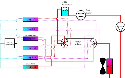
The flow in the regenerator is reciprocating; nevertheless, through us-ing a number of similar regenerators in parallel, but with phase-shift in their cycles, the flow in the heat exchangers can be continuous and unidi-rectional. For example, in the system shown in Figure 3 (the same system described in more details with reference to Figure 49, inserted here again for convenience), six pairs of regenerators are used in parallel with the phase shift in their flow rates according to Figure 4. In this way, there is always flow with the same rate that leaves the warm end of the regenera-tors and goes to hot heat exchanger (positive flow in Figure 4) and flow with the same rate that leaves the cold end of the regenerators and goes to the cold heat exchanger (negative flow in Figure 4). The regenerators are paired in this example; however, to have continuous flow there is no need for the regenerators to be paired.
Figure 3. A system with 6 pairs of regenerators and the flow distributed between them by
the rotary valve according to Figure 4. (More details about the system is given in Appendix A)
Figure 4. Phase shifted flow in each of the 6 parallel pairs of regenerators shown in Figure 3
The built prototypes with active magnetic regenerators are numerous. They are reviewed in two comprehensive, recently published works by Balli et al. (2017) and Kitanovski et al. (2015); therefore, an exhaustive re-view is not included in this thesis.
Among the designs in which the relative movement of magnet assem-bly and the magnetocaloric materials is reciprocating, the performance of the device reported by Yao, Gong, and Wu (2006) is remarkable. In their design two packed beds of gadolinium are moving in and out of two fixed magnet assemblies. The magnet assemblies create 1.5 T magnetic field and the total mass of gadolinium is 1.167 kg. The cooling capacities ob-tained over 18.2 K and 40.5 K temperature spans are about 51.3 W and 10 W.
Usually the devices in which the rotary movement of the magnet as-sembly relative to the regenerators causes the change in the magnetic field operate at higher frequencies and provide more cooling capacity compared to reciprocating devices. Among the rotary devices, the proto-type presented by Jacobs et al. (2014) provides 2502 W cooling capacity over 11 K temperature span; however, as the temperature span ap-proaches 18 K the cooling capacity becomes nearly zero. This significant cooling power with 11 K temperature span is obtained with 1.52 kg of La(Fe,Si)13H distributed in 12 epoxy-bonded packed beds and maximum
magnetic field of 1.44 T. Another high performing rotary device is pre-sented by Bahl et al. (2014). In that prototype, 2.8 kg spherical gadolin-ium particles are divided into 24 packed beds. The average magnetic field in the high field regions created by the assembly of permanent magnets is about 0.9 T. With this prototype the cooling capacities of 200 W and 400 W are obtained over temperature spans of 18.9 K and 13.8 K.
A notable, newer prototype not included in the reviews by Balli et al. (2017) and Kitanovski et al. (2015) is presented by Lozano et al. (2016). This prototype has 16 regenerators and a rotary magnet assembly placed inside the cylindrical arrangement of the regenerators. An advantage of this prototype is its magnet design, in which the magnet materials are used sparingly to create the needed change in the magnetic field in the space occupied by the housing of the regenerators. With 1.7 kg gadolin-ium spherical particles, 12 K temperature span at no-load condition and 150 W cooling capacity at zero-span is obtained. The highest obtained Carnot efficiency is slightly below 1.2 % with temperature span of 7.1 K and cooling capacity of 80.4 W.
Our prototype at KTH Royal Institute of Technology is also not cov-ered in those reviews. This prototype is first presented publicly by Mon-fared and Palm (2016). Further details are given later in Paper B and also
Appendix A of this thesis. The performance of the prototype and the pos-sible improvements in its design are investigated in section 3.5 and chap-ters 5 and 6.
1.3.2.1 Loss mechanisms in an AMR device
The loss mechanisms inside or related to the regenerators in an AMR cy-cle are: viscous dissipation as the HTF flows through porous regenera-tors; axial heat conduction from the warm end to the cold end of a regen-erator via magnetocaloric materials and HTF; heat transfer from the cold end to the warm end via the materials surrounding the regenerator such as the housing of the regenerator; heat transfer over finite temperature difference; heat transfer from the ambient to the regenerator; eddy elec-tric current in MCM (Burdyny and Rowe 2013); channeling effect and maldistribution of HTF in regenerator (Lei et al. 2017, Nielsen et al. 2011); mixing of the HTF leaving and the HTF entering each end of re-generator in dead volumes (Jacobs 2009); imbalance in reciprocating flow rate through a regenerator in different directions (Eriksen et al. 2016); inhomogeneous properties of MCM in each layer (Smith et al. 2012); irreversible magnetization due to hysteresis (Basso et al. 2006).
External to the regenerators the loss mechanisms are: eddy electric current in conductive materials sensing the change in the magnetic field; motor and power transmission losses; friction in moving parts; pressure drop outside regenerators.
The problem of dead volumes is related to the reciprocating flow through the regenerators. If there are spaces adjacent to a regenerator where the colder and warmer HTF leaving and entering the regenerator can mix, it adds to the losses. However, these volumes can be avoided if at each end of the regenerators there are separate inlets and outlets for heat transfer fluid (Bahl et al. 2014, Engelbrecht et al. 2012). Therefore, in this thesis this loss mechanism is not taken into account.
No imbalance in flow rates going back and forth through the regenera-tors is considered in modeling. In the experimental tests used for valida-tion of the model the flow rates in the two direcvalida-tions were equal thanks to the positive displacement pump used which supplies a constant flow rate in its working range regardless of the pressure drop.
Inhomogeneity of properties of MCM is discussed further in section 6.1.4. Channeling effect and maldistribution of the flow is discussed fur-ther in section 1.4.
The eddy current in the yoke surrounding the regenerators in the ex-perimental setup is minimized by laminating the yoke (see Appendix A). In this project only packed bed of particles is considered as regenerator; therefore, the eddy current in magnetocaloric materials is neglected con-sidering the point contact between the particles and that they are not ex-cellent electric conductors.
The losses due to hysteresis is not investigated in this thesis consider-ing that the magnetocaloric materials used in modelconsider-ing the performance of AMR cycle show either no hysteresis, Gd (Gutfleisch et al. 2016), or low, negligible hysteresis, La(Fe,Mn,Si)13Hz (Gutfleisch et al. 2016,
Morrison et al. 2012).
The losses due to friction in moving parts and pressure drop outside the regenerators are not included in the analyses presented in the thesis since they are dependent on specific design of each machine and are of secondary importance.
The rest of the loss mechanisms mentioned in this section are included in the analyses reported in this thesis when they are relevant.
1.3.3 Solid-state magnetic refrigeration
Solid-state magnetic refrigeration is a less investigated alternative to AMR cycle. In solid-state magnetic refrigeration the heat transfer fluid is eliminated and replaced by heat switches*. Heat switches or thermal
di-odes are devices in which the rate or direction of heat transfer can be con-trolled. A simple example of a heat switch is a mechanism bringing two surfaces into contact to increase the heat transfer rate through them or separating them to hinder the heat transfer. The physical phenomena and devices that can be used to control the rate or direction of heat transfer are numerous and are summarized by Kitanovski et al. (2015) considering their application in solid-state magnetic refrigeration and by Wehmeyer et al. (2017) with focus on room-temperature applications, but not neces-sarily in magnetic refrigeration.
* The other names that Kitanovski et al. (2015) have mentioned for heat switch are thermal diode, heat semiconductor, thermal switch, heat valve, and thermal rectifier. However, Wehmeyer et al. (2017) differ-entiate between thermal diodes and switches by making analogy to electrical components. The loose us-age of these terms instead of each other in solid-state refrigeration literature can be understood consider-ing that the heat switches are, in this field, used to rectify the heat flux to mimic diodes. In this thesis the name heat switch is chosen although in the appended articles the term thermal diode is used. The term heat switch is preferred over thermal switch to avoid confusion with the well-known electric component, which can be used as a thermostat, to cut off the electrical current when it becomes warm.
The research on solid-state magnetic refrigeration is motivated by the possibility of eliminating pressure drop in the regenerator, eliminating complications of the hydraulic system, and increasing the cycle frequency (larger cooling capacity for more compact device) (Kitanovski et al. 2015). The pressure drop in the AMR cycle leads to viscous dissipation in the re-generator and extra input work to the system as pump work. Although the heat switches are commonly used in low-temperature magnetic refrigera-tion devices (Kittel 2002), the use of them in room-temperature magnetic refrigeration devices is first suggested by Kitanovski and Egolf (2010).
Most of the research work done on room-temperature, solid-state, magnetic refrigeration is based on the design shown schematically in Fig-ure 5.
Figure 5. Most common cycle for solid-state magnetic refrigeration systems
In the first step, all of the heat switches are inactive and the odd MCM layers (which are shown in red in Figure 5a) are magnetized. Due to mag-netization, the temperature of these layers is higher than the initial tem-perature at the beginning of the cycle. In the second step the even heat switches are activated while the rest of the heat switches remain inactive. As a result the heat is transferred from the warmer, magnetized materials to the colder, demagnetized layers to their right in Figure 5b. In the third
step, all of the heat switches are inactive again and the odd MCM layers are demagnetized, while the even MCM layer are magnetized and warm (shown in red in Figure 5c). In the last step of the cycle, the odd heat switches are active allowing heat transfer from warmer layer to the colder ones to their right in Figure 5d.
The research works using the design shown in Figure 5 are as follows: Tasaki et al. (2012) have compared the performance of an AMR system with that of a solid-state one via software modeling for mobile air-condi-tioning application. In their model, it is assumed that the heat switches, disregarding the actual mechanism for implementation, have zero ther-mal conductivity when they are open and have infinite therther-mal conductiv-ity when they are closed. In addition, the magnetocaloric material is as-sumed to have constant heat capacity, constant 5 K adiabatic temperature change, and infinite thermal conductivity resulting in no temperature gradient in each layer in the axial direction. Tsukamoto et al. (2012a, 2012b) have tested nearly the same design depicted in Figure 5 but with a single layer of MCM and indirect contact between the heat switches and MCM via a silicon holder for MCM. The aim of their experimental work is to investigate the possibility of employing magnetic refrigeration for ap-plications requiring small cooling capacities in order of micro-Watts. Ol-sen et al. (2014) have modeled a solid-state device similar to what is mod-eled by Tasaki et al. (2012) with application in mobile air conditioning. Similar to the work of Tasaki et al. (2012), no specific mechanism is con-sidered for the heat switches but the assumed conductivity of the heat switch is a finite value when it is closed. The stated aim of the study done by Olsen et al. (2014) is to investigate the ultimate limits for application of a solid-state magnetic refrigeration technology in mobile air condition-ing. Silva et al. (2014) have also investigated a design schematically shown in Figure 5 via software modeling. In their work it is also assumed that the thermal conductivity of the heat switches is either zero when open or a finite value when closed and the excitation of the heat switches is done by a magnetic field with negligible work. The present author has considered the limited conductivity of the actual MCM and closed heat switches and also the axial conduction in adverse direction via the open heat switches in his simulation model (Paper F). The use of non-ideal MCM and heat switches has revealed that the gain in cooling capacity from increased frequency in solid-state magnetic refrigeration devices is not unlimited. Monfared (2017) has developed a detailed simulation
model of multi-layered, solid-state, magnetic refrigeration devices in which Peltier elements are used as heat switches. In this work the transi-ent behavior of Peltier elemtransi-ents and MCM layers are simulated and the details of the modeling and validation processes are explained. In addi-tion, the results for two scalable cases with different working tempera-tures are presented and optimization of parameters is done for one of the cases (Paper E).
Tomc et al. (2013, 2014) have investigated an alternative design for solid-state, magnetic refrigeration devices. In their work a long, thin sheet of MCM with 40 Peltier elements, as heat switches, on each side is mod-eled. Both cold and hot heat exchangers have the same width and length as has the MCM sheet and are placed parallel to the sheet, but separated from it by the Peltier elements. After magnetizing the sheet of MCM the Peltier elements on one side of the sheet are turned on so that they take the heat from the warm, magnetized MCM and transfer it to hot heat ex-changer. At the same time water flows along the axial direction of the warm heat exchanger from the cold end to the warm end. In the next step, the magnetocaloric material is demagnetized and the Peltier elements on the other side, which served as insulation in the previous steps, are turned on to take the cooling load from the cold heat exchanger to the MCM sheet. As these Peltier elements transfer the heat from the cold heat exchanger to MCM, water flows along the axial direction of the exchanger from the warm end to the cold end. In this design the flows in the heat ex-changers are intermittent. The simplifications made in this study are that the steady-state performance of Peltier elements with constant tempera-ture lift of 0.3 K between their two ends are used; axial conduction in the MCM sheet, fluids, thermal switches, and the heat exchangers is ne-glected; thermal conductivity of the heat exchangers in transvers direc-tions is assumed infinity. The design proposed by Tomc et al. (2013, 2014) is further investigated by de Vries and van der Meer (2017) using a more detailed simulation model. In the modeling done by de Vries and van der Meer (2017) the flow in the heat exchangers is continuous; the flow circuits of the cold and hot heat exchangers are not separated; a smaller thermal resistance for inactive heat switches is considered; tran-sient thermoelectric effect is modeled instead of using steady-state per-formance of Peltier elements; the axial thermal conduction is taken into
account; the heat capacity of MCM is assumed independent of the mag-netic field. As a result, de Vries and van der Meer (2017) have predicted lower performance for this design.
In a system described by Bartholomé et al. (2016), the conventional compressor of a vapor-compression cycle is replaced by an innovative type of compressor comprised of MCM, a magnet assembly, and heat switches. In their work the gaseous refrigerant still exists and it becomes cold via typical expansion process of vapor-compression cycle, not be-cause of demagnetization of MCM. Presence of the gaseous refrigerant cancels one of the advantages of magnetic refrigeration, which is elimi-nating the leakage of greenhouse gases. Although Bartholomé et al. (2016) have mentioned rarely used refrigerants such as water and ethanol to be used in their proposed system, their design faces the inherent short-comings of these refrigerants: working at subatmospheric pressures in room-temperature applications and extremely large required volumetric flow rate of refrigerant to provide enough cooling capacity. These inher-ent shortcomings are the same reasons why water or ethanol are rarely used in the conventional vapor-compression systems.
Silva et al. (2016) have investigated the effect of the properties of MCM including density, heat capacity, adiabatic temperature change, and con-ductivity on the performance of a single-layered solid-state refrigeration system. The study is done for no-load conditions with some simplifica-tions such as independence of heat capacity on magnetic field. Egolf et al. (2014) suggest Peltier elements as heat switches for solid-state magnetic refrigeration devices. In their article, the basics about Peltier elements and their steady-state performance are explained. They have also done a preliminary, approximate estimation of the performance of the future solid-state magnetic refrigeration devices.
1.4 Packed bed regenerators
The most common structure for the porous medium used as active mag-netic regenerator is packed bed of MCM particles. Although the viscous dissipation and required power to pump HTF through packed beds is rel-atively high, it has the advantage that the heat is transferred with higher rate compared to the alternative structures such as parallel plates and mini-channels (Lei et al. 2017). In addition, packed beds are easy to build, while manufacturing limitations do not allow to build parallel plates or mini-channels with the desired thickness of walls and void spaces. The
thick walls hinder the heat transfer from the inner parts of the solid to the heat transfer fluid considering the relatively low thermal conductivity of magnetocaloric materials, and too large void spaces prevents the efficient use of the magnetized space. In addition, the limited manufacturing pre-cision results in maldistribution of the flow and uneven thickness of the walls, which affect the performance of the regenerators adversely (Lei et al. 2017, Nielsen et al. 2014, Tušek et al. 2014). Another possible structure for active magnetic regenerators is packed screen bed which causes less pressure drop without compromising heat transfer between solid and fluid; however, manufacturing screens with desired size with the cur-rently existing magnetocaloric materials and technologies is not trivial (Lei et al. 2017). In this thesis, the focus is on packed beds as active mag-netic regenerators, since it is currently the most viable alternative in prac-tice.
The ratio of the volume left between the solid particles (filled with a fluid) to the total volume of the bed is called porosity, ε. In packed beds the flow faces less resistance close to the walls of the bed housing. The reason is that the arrangement of the particles, due to the presence of the solid wall, is different from the inner areas of the bed. This lower re-sistance to flow results in higher velocities at areas with larger local po-rosity close to the wall. This phenomenon is called channeling. However, in the modeled packed beds in this project the local variations of the po-rosity are disregarded and an average bulk popo-rosity for the whole bed is used since most of the relationships developed for packed beds are not validated for cases with significant gradient in the porosity (Kaviany 1995).
Superficial velocity (or filter velocity), VD, is defined as the volumetric flow rate divided by the cross section area of the bed (Macdonald et al. 1979). Specific surface area of a packed bed, Eq. (4), is the ratio of the sur-face area of the solid-fluid intersur-face to the total volume of a packed bed. For a packed bed of uniformly-sized spheres the specific surface area is equal to 6(1-ε)/dp. 𝑎 =𝐴𝐻𝑇 𝐴𝑐𝐿= 1 𝐴𝑐 𝑑𝐴𝐻𝑇 𝑑𝑥 (4)
In the correlations used to evaluate the pressure drop and solid-fluid heat transfer coefficient the macroscopic superficial velocity is used. However, the effect of local, microscopic velocity fields formed in the complex void spaces left between the solid particles is also taken into ac-count by modifying the model of conductive heat transfer. The influence of the pore-level velocity fields on the temperature field, and thereby, heat transfer is referred to as dispersion (Kaviany 1995). The effective thermal conductivity in axial direction for a fluid flowing in a packed bed is given by Eq. (5) to include the dispersion effect. Reynolds number, Red, is de-fined in Eq. (6) (Amiri and Vafai 1998).
𝑘𝑒𝑓,𝑓= 𝑘𝑓(𝜀 + 0.5𝑅𝑒𝑑𝑃𝑟) (5)
𝑅𝑒𝑑=𝜌𝑓𝑉𝐷𝑑𝑝 𝜇𝑓
(6) The effective thermal conductivity of the solid phase is given by Eq. (7) (Amiri and Vafai 1998).
𝑘𝑒𝑓,𝑠= (1 − 𝜀)𝑘𝑠 (7)
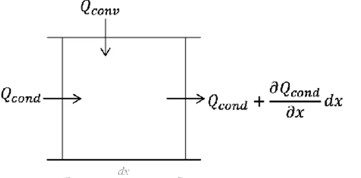
The Eqs. (5) and (7) evaluate the effective axial conduction along the regenerator by modeling the fluid phase as plug flow with an added term to take dispersion into account and modeling the solid material, as a sep-arate phase, as a continuous bar. In this simplified model of axial conduc-tion, the cross section areas of the solid and fluid phases are uniform and proportional to the volume occupied by each phase (see Figure 6). With such separation in the conductive heat transfer through the solid and fluid phases in the regenerators, where the temperatures of solid phase and fluid phase are not assumed equal, it is clear that the evaluated effec-tive conductivity given by Eq. (5) should be used together with axial tem-perature gradient of the fluid and the value given by Eq. (7) should be used together with the axial temperature gradient of the solid.
Figure 6. Separating solid and fluid phases and modeling conductive and dispersive heat
transfer in them. This is a reproduced figure obtained from the “continuous solid phase model” explained by Wakao and Kaguei (1982) and discussed in details in section 3.1.
An alternative way of evaluating the conduction and dispersion in axial direction is to separate the static conduction from the dispersion term. The correlation used by many authors for evaluating the static conductiv-ity is Eq. (8), given by Hadley (1986), in which an equivalent static con-ductivity for the mixture of the two phases is calculated. In the first term in Eq. (8), the two extreme values of f0=0 or f0=1 simplifies that term to the cases in which the conductive thermal resistance of the fluid phase and the solid phase are assumed being in series or being parallel. That is, with f0=1 the equivalent static conductivity of the mixture becomes
εkf+(1-ε)ks which means the two phases conduct the heat in parallel in the axial direction. It should be noted that a) the same simplification, as done in Eqs. (5) and (7), is also done here by assuming the solid and fluid ma-terials as a bar with uniform cross section area; b) with f0=1, the first term of Eq. (8) reduces to the sum of the static parts of Eqs. (5) and (7); c) with
f0=0.8+0.1ε, given by Kaviany (1995), f0 is about 0.84 for randomly packed beds. That is, the combined axial static conduction of the two phases given by Eq. (8) is not far from the static parts of Eqs. (5) and (7) which act as parallel thermal resistances. The second term, weighted by
α0, models solid particles suspended in a fluid without touching or ther-mally affecting each other, which is irrelevant for the packed beds used as active magnetic regenerators. The weighting factor for the second term is about 1—3% for the porosities between 0.36 and 0.44 using the correla-tion log(α0)= -1.084 -6.778(ε-0.298), given by Kaviany (1995); thus, it is in practice eliminated when the calculations are done for randomly
packed beds. Although Eq. (8) models the regenerator and the heat trans-fer fluid as a single phase, it is used in active regenerator models in which the solid and fluid phases are distinguished by considering the tempera-ture difference between them. The difficulty with such adaptation, alt-hough it may not affect the results considerably, is justifying the choice of one of the phases, to which this equivalent static conductivity of the mix-ture of the two phases applies. For the both compared methods, it is closer to the actual physics of the problem that the dispersion term is ap-plied to the fluid phase. Kaviany (1995) has tabulated a number of other correlations which also give an equivalent conductivity of the combined phases; however, because of the same difficulty in using them in models in which the temperature of the two phases are not assumed the same, they are not used in this work. In addition, some of them are obtained with assumptions that do not apply to the packed beds modeled in this project. 𝑘𝑠𝑡𝑎𝑡𝑖𝑐,𝑚𝑖𝑥 𝑘𝑒𝑓 = (1 − 𝛼0) 𝜀𝑓0+𝑘𝑠 𝑘𝑓(1 − 𝜀𝑓0) 1 − 𝜀(1 − 𝑓0) + 𝜀𝑘𝑠 𝑘𝑓(1 − 𝑓0) + 𝛼0 2 (𝑘𝑠 𝑘𝑓) 2 (1 − 𝜀) + (1 + 2𝜀)𝑘𝑠 𝑘𝑓 (2 + 𝜀)𝑘𝑠 𝑘𝑓+ 1 − 𝜀 (8)
Wakao and Kaguei (1982) have suggested Eq. (9) to calculate solid-fluid convective heat transfer coefficient for packed beds. To take the thermal resistance of particles into account this coefficient is corrected according to Eq. (10) (Dixon and Cresswell 1979, Nield and Bejan 2013).
ℎ𝑠𝑓=𝑘𝑓 𝑑𝑃(2 + 1.1𝑃𝑟 1 3 ⁄ 𝑅𝑒 𝑑0.6) (9) 1 ℎ𝑠𝑓,𝑐𝑜𝑟𝑟 = 1 ℎ𝑠𝑓 + 𝑑𝑃 10𝑘𝑠 (10)
The general form of pressure gradient along a packed bed is
C1VD+C2(VD)2, where C1 and C2 are proportionality constants, the linear term is associated to viscous effects, and the quadratic term is associated with inertial effects (Macdonald et al. 1979). The modified Ergun equa-tion suggested by Macdonald et al. (1979), Eq. (11), gives the pressure gra-dient for a packed bed made with smooth, spherical particles.
−𝑑𝑃 𝑑𝑥= 180(1 − 𝜀)2𝜇 𝑓 𝑑𝑝2𝜀3 𝑉𝐷+ 1.8𝜌𝑓(1 − 𝜀) 𝑑𝑝𝜀3 𝑉𝐷2 (11)
1.5 Summary of the chapters
The basics of magnetic refrigeration is explained in the introduction chapter. In the next chapter, the environmental impacts of magnetic re-frigeration in comparison to the vapor-compression technology is dis-cussed with a holistic approach using life cycle assessment as a tool. Chapter 3 is dedicated to describing the computer model developed to simulate the performance of magnetic refrigeration systems. This simula-tion program, which is utilized in chapters 4, 5 and 6, is useful in optimiz-ing the design of magnetic refrigerators; makoptimiz-ing comparison between the performance of magnetic refrigeration systems with the performance of devices using other technologies; investigating the ways of reducing the environmental impacts through improvements in design and materials. Chapter 4 addresses the need for optimal choice of materials for an active magnetic regenerator as the core of magnetic refrigeration systems. In chapter 5 the study done to redesign and to optimize the active magnetic regenerators of a prototype is presented. In chapter 6 the requirements for the magnetocaloric materials (the refrigerant in magnetic refrigera-tion systems) are investigated via comparison between the performance of the currently existing vapor-compression systems and simulated equiv-alent magnetic refrigeration systems. Chapter 7 is about solid-state mag-netic refrigeration with heat switches instead of heat transfer fluid, which is a less explored research area. In appendix A, the magnetic refrigeration prototype existing at the Department of Energy Technology, KTH Royal Institute of Technology, is described. This prototype is referred to several times in different chapters.
2
Life cycle assessment and environmental impacts
One of the advantages of magnetic refrigeration systems, compared to va-por-compression systems, is that the possibility of leakage or release of gaseous refrigerants to the ambient is eliminated. Since some of the con-ventional, gaseous refrigerants used in vapor-compression cycles are green-house gasses, eliminating the possibility of their leakage to the am-bient is considered by many researchers equivalent to magnetic refrigera-tion being a more environmentally friendly technology. However, it is not necessarily the case since potential leakage or release of gaseous refriger-ants to the ambient is a part of the whole life cycle of a vapor-compres-sion system, while in other parts of the life cycle it may have less environ-mental impacts compared to a magnetic refrigeration system. In addition, the environmental impacts of a system are not limited to its contribution to global warming.
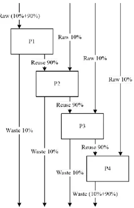
Accordingly, for evaluating the environmental impacts of magnetic re-frigeration systems, a holistic approach covering all phases of their life cy-cle and all types of the environmental impacts associated with them is needed. As reported in Paper A, Life cycle assessment (LCA), which is used in this project to evaluate the environmental impacts of a magnetic refrigeration system, is a tool meeting the requirements of such a holistic approach. Figure 7 shows the system boundary and the major processes included in the assessment done in this work. The software program used for doing the LCA is SimaPro 7.3.3. The data for life cycle inventory anal-ysis are mainly taken from ecoinvent database v2.2 and European Life Cycle Database (ELCD) v2.0, as implemented in Simapro 7.3.3. In this as-sessment, it is assumed that the whole lifecycle of the refrigerators is in Europe and therefore the electricity mix used in the assessment is the av-erage electricity production of 28 European countries weighted by their production rate, “Electricity, production mix RER/RER U” in ecoinvent database v2.2, as implemented in SimaPro 7.3.3.
Figure 7. The inputs, outputs, and the main processes included in the LCA
The goal of making a life cycle assessment determines the implementa-tion of the assessment, and thereby, affects the results and possible con-clusions drawn from the results. In this study the life cycle assessment is done with a forward-looking approach with the goal to answer the follow-ing questions:
1. If room-temperature magnetic refrigeration technology becomes ma-ture enough that a magnetic refrigeration system with reasonably com-pact design can fulfil the same functions as does a vapor-compression system, will it be necessarily a more environmentally friendly system? 2. What are the main contributors to the environmental impacts of a
magnetic refrigeration system and how can the impacts be lowered? The first question is a broad question covering all imaginable applica-tions of room-temperature magnetic refrigeration, whereas investigating all such systems is not practical. For that reason, a specific set of func-tions for both magnetic and vapor-compression refrigeration devices, re-ferred to as “functional unit” in Paper A, is used for the comparative life cycle assessment in this project. This specific set of functions indicates that the comparison is made between a magnetic and a vapor-compres-sion household refrigerator with equal and known volume of refrigerated compartment; total volume; energy efficiency class; annual energy con-sumption; climate class. Although the quantitative results obtained for