http://www.diva-portal.org
Postprint
This is the accepted version of a paper presented at IDETC/CIE 2016, International Design
Engineering Technical Conferences & Computers & Information in Engineering Conference.
Citation for the original published paper:
André, S., Stolt, R., Elgh, F. (2016)
A platform model for suppliers of customized systems: Creating an ability to master fluctuating
requirements.
In: Proceedings of the ASME 2016 International Design Engineering Technical Conferences &
Computers and Information in Engineering Conference, IDETC/CIE 2016, Charlotte, August
21-24, 2016.
N.B. When citing this work, cite the original published paper.
Permanent link to this version:
A PLATFORM MODEL FOR SUPPLIERS OF CUSTOMIZED SYSTEMS – CREATING
AN ABILITY TO MASTER FLUCTUATING REQUIREMENTS
ABSTRACT
Companies developing highly customized products within the supplier industry are continuously faced with fluctuating requirements during both the quotation process and continued development. This research proposes a platform approach to aid suppliers when modularity or platform scalability do not suffice. The platform approach, Design Platform, focuses on descriptions that not only contain information about tangible components and systems but also information, knowledge and methods supporting the actual design of the product. A support system called Design Platform Manager has been developed to aid in using the platform approach and is introduced at a supplier active in the automotive industry. The system enables creation of generic product items that can be structured and instantiated to become product variants as well as Design Elements that are blocks of knowledge that describe a design or supports the activity of designing. A first evaluation is made that overall shows good result according to the company representatives.
Keywords: Quotation, Customization, Platform, Requirements,
Supplier, Engineering Design
INTRODUCTION
The automotive supplier industry faces great challenges when it comes to developing highly customized products and systems. The challenges concern reducing prices, increasing quality and decreasing time to market. One vital step in the product development process is the quotation process. Suppliers find themselves in a competitive race when trying to win product development projects for the Original Equipment Manufacturers (OEMs). It is therefore vital to answer quickly to the quotation request but also to do so with a high level of accuracy at the same time guaranteeing an effective use of company assets. Following the quotation stage is the design process that focuses on the development of the actual order and
often has a longer time horizon than the quotation process. In this phase requirements and interfaces tend to fluctuate which makes it crucial to acknowledge the changes and adapt the design work to the new situation.
When focusing on companies designing highly customized systems, the development of new knowledge is intense. This stresses for methods and models to better host the outcome of both product development as well as technology development. But how can highly customized systems be efficiently customized at the same time guaranteeing a high level of reuse of company assets in an environment where requirements fluctuates heavily throughout the course of product development? A concept that has been around for several years but mostly focused on tangible things is the product platform. The main concept of the product platform is to focus the development towards a structure that in some way is the common base of several product variants. However, research has shown that this kind of platform is not applicable to several suppliers of highly customized products [1] in a business to business (B2B) environment. The reasons for this is heavily changing and fluctuating requirements and unknown future interfaces. A supplier component based product platform would need to be able to serve several brands and cope with all kinds of customer specific requirements on e.g. product differentiation and levels of functionality which has been judged as a hard task if even possible for all companies.
Setting the scope
The methodologies and models for working with platforms have for a long time mainly supported the physical component-based product platform. Descriptions and implementations of working platform-based at a higher level than components and subsystems are scarce. It is however assumed that the positive effects from using a component-based platform can also be harvested when it comes to outcome that is on a higher level of abstraction or at least not as close to be realized as a product.
Samuel André Jönköping University Jönköping, Sweden Roland Stolt Jönköping University Jönköping, Sweden Fredrik Elgh Jönköping University Jönköping, Sweden
Proceedings of the ASME 2016 International Design Engineering Technical Conferences and Computers and Information in Engineering Conference IDETC/CIE 2016 August 21-24, 2016, Charlotte, North Carolina
Examples of these outcomes can be formalized tasks, guide-lines, constraints, parametric models, simulation models and that people gain new knowledge. An issue with product platforms is that they are rarely allowed to evolve within their platform lifecycle. For suppliers of customized systems in a B2B situation however, the uncertainty regarding future OEM requirements and interface changes requires a platform description that is allowed to evolve over time. This paper presents a model called the Design Platform and support tool called Design Platform Manager that aims to support such a working approach. Figure 1 visualizes the introduction of the Design Platform in the presented setting and given prerequisites. The long term goal of the research is to make companies acting as suppliers, developing highly customized products, more responsive to changing and fluctuating requirements at the same time improving both speed and accuracy in the quotation process and subsequent product development process. The aim of this paper is to explore how a platform approach could be formulated, given the above prerequisites, and how a software tool could be designed to support the platform approach.
Figure 1 Introducing the Design Platform to enable customization for suppliers of customized systems
Methodology
The model presented in this paper has been developed in a project where four companies participate. All four companies are suppliers of highly customized system in a B2B environment. The case of application has been conducted in close collaboration with one of those companies. The information about the presented case has been gathered from meetings, demonstration of applications, reviews of documents, in-depth interviews and co-development of method and support system. A systematic literature review was made and the Frame of Reference presented in this paper can be seen as a summarized version of the complete literature review. The overall research approach used in this work is a Design Research Methodology (DRM) proposed by Blessing and Chakrabarti [2]. The methodology divides a research project in four stages: Research Clarification (RC), Descriptive Study I (DSI), Prescriptive Study (PS), Descriptive Study II (DSII). As proposed by the research methodology, Success Criteria where
identified in cooperation with the four companies. This was done by identifying crucial factors that would judge if the research project had succeeded or not. When these had been decided, units of measure were identified in order to make the Success Criteria measurable. The company then picked the most important Success Criteria in order to set the focus of the case. These Success Criteria have been used as the base when creating the questionnaire for the evaluation in this study.
FRAME OF REFERENCE
Customization refers to the ability and strategy that aims towards designing and manufacturing tailored products for an individual customer. Hansen [3] categorizes customization into four levels whereas the first is the highest level:
Engineer-to-order, Modify-to-order, Configure-to-order, and Select variant. An important aspect of customization is the ability to manage requirements and much has been done in the areas of consumer products [4] and configurations systems [5]. However, the prerequisites of customizing for an end consumer compared to an OEM are different and different methods have been used throughout past research. Suppliers developing highly customized systems in a B2B environment are often required to stretch the boundary every new product development project which forces them to explore new grounds regarding designs and the way they conduct design. The dynamic nature of requirements in this environment often result in changes or that new requirements are added or others are dropped, this has been investigated in the automotive industry in [6]. The author continues stating that it is a natural process since knowledge is gained and prerequisites change throughout the project. Other reasons for changing requirements are competitor-, product-, market-, and project evolution as well as misunderstandings due to the lack of clear requirement specifications [7]. All of these reasons contribute to the challenge of creating a component based platform with standardized interfaces for these kinds of companies.
Platform definitions and scope
The definitions of what a platform is or could be spans a notable space. The most used and applied definition focuses on tangible things and is formulated by [8] as “A set of common components, modules, or parts from which a stream of derivative products can be efficiently developed and launched.”. A more abstract definition is done by [9]: “The collection of assets [i.e., components, processes, knowledge, people and relationships] that are shared by a set of products ”. Other available definitions usually fit in between these two. This scope of definitions makes Johannesson [10] questions if companies have a choice regarding implementing a platform or not since platforms can exist on several levels.
A risk with using a product platform approach is the trade-off between commonality and distinctiveness [9]. This has also been subjected to much optimization as summarized by [11]. Although not much research has been conducted on suppliers developing highly customized products at supplier level. A
Future market opportunities and needs
OEM Design Platform Technology development Product development Requirements Supplier Quotation RFQ End customer
platform formulation for a supplier with a small batch production is investigated by [1, 12]. The authors arrives at that a modular platform is not seen as feasible in such a company since most of the reuse is found on a higher level of abstraction. Platform formulations are investigated among suppliers in [13], where the platforms are categorized on what level of abstraction they are defined. Cooper [14] suggests that one deliverable from technology development can be a technology platform which is further investigated by Högman [1]. The author presents a technology platform definition that is not connected to a specific implementation (as a product platform is) but is rather consisting of design knowledge, product concepts, applied technology and technological capabilities in order to support product realization. Guðlaugsson et al [15] describes a tool called Conceptual Product Platform which has been based on the concept of technology platforms. The aim is to communicate the product portfolio by mapping application requirements through concepts, to the product organs which is the physical features that realizes the functions.
In order for a product platform to be described and for its abilities to be communicated a model of the platform is highly suitable. The Product Variant Master (PVM) is a tool that can to some extent be used to model a product platform [5]. The main aim of the PVM is to map a company variant flora and couple them to a generic product architecture in order to create a foundation for introducing configuration systems. Another methodology that can be described as a platform model is the Configurable Component concept [16]. Instead of modeling the connections between physical parts and modules, as in the PVM, the connection from functional requirement to design solution is mapped. Levandowski et al [17] proposes a methodology to model a platform in early phases of development using the Configurable Component concept and Set-Based Concurrent Engineering. The platform abilities are modelled using bandwidths and Set-Based Concurrent Engineering is used to gradually narrow the design space. Bruun [18] et al presents an approach for using a visual product architecture model in combination with a PLM system for supporting the activities of developing modular product
families. Hölttä-Otto et al [19] investigates the implications of
level of granularity and view point when decomposing a product architecture when planning product platforms.
Reuse of design knowledge
Baxter [20] considers knowledge as actionable information and problematizes that many previous design knowledge reuse systems exclusively focuses on geometrical data which is often not applicable in early stages of development. Future reuse models need to contain problem solving methods, solution generation strategies, design intent and project knowledge. Stokes [21] presents a complete framework and in detailed described methodology, called MOKA, aiming to collect and formalize knowledge in order to create knowledge based systems. The knowledge is gathered from domain experts using standard templates, called ICARE forms, which together forms
an informal model. An important aspect of the design reuse research is design rational. Regli et al. [22] defines design rational as the explanation of why an artefact or some part of an artefact is designed the way it is. A complete design rational includes all background knowledge, reasoning, trade-offs made and decisions taken during the design process. According to [23] the access to design rational can support the development of new products, modification of existing ones or reuse of an existing one in a new context. [24] describes the methodology for developing a knowledge map and also the implementation in a company acting in the automotive interior business. Elgh [25] describes the development of a design automation system to aid in the quotation process which includes modelling of processes and knowledge.
Summarization and research opportunities
This literature overview has shown that a platform approach is an enabler for efficient customization and reuse. There is however a lack of research describing how suppliers of customized systems can draw the benefits from platform thinking. There are not many examples of support methods and tools actually aiding the design engineers using such a platform definition. There is also not much mentioned of what knowledge descriptions actually support a platform definition of this kind and how these descriptions can be structured in order to improve reuse and efficiency.
INTRODUCING THE DESIGN PLATFORM APPROACH
Platform thinking is a main enabler for reuse as a way to keep the design effort efficient and at a manageable level. What often is lacking is a platform description to bind the development outcomes together in a standardized format. To start by designing a common structure is not seen as completely feasible since future variants cannot be preplanned when a company uses a business model that allows a high degree of customization and responsiveness to customer specific requirements. In the Design Platform (DP) approach, the platform is defined by:
• Descriptions of product instances and their interrelation to a generic description, which means that the platform evolves as the instances are successively created.
• Descriptions of the building blocks of the designs and design process and the both generic and specific descriptions of those.
Both kind of descriptions focuses on the reuse of company assets which can be of different kinds. Also, both kind of descriptions can be the starting point of defining a product variant. The proposed concept is based on an object oriented view. The idea is to see a generic product item as a class, when instantiated becomes an instance (object). The generic product item can in many times be in the form of a generic product structure but also in the form of a generic module or component. Design Elements (DEs) can then be associated with the items.
DEs are discretized blocks of knowledge descriptions and are instantiated from classes of their own.
The starting point of the model is the identification and definition of generic product item. These can be seen as the common base to which different constructs and descriptions can be linked. These items might not correspond to an already existing design, however it is known that the item must be included in the finished design. The DP approach proposes that the item can be bi-directionally linked to other kinds of descriptions. Bi-directionally in the sense that the item might require that a specific description is used in the construction of the item or vice versa, the starting point is a DE which in turn defines the item.
Two views can be used in DP model. A generic product item view and an instance view. The instance view is a list of all instances, i.e. objects, which have been instantiated from a generic product item, i.e. the class. This view contains the information used for creating the specific instance in order to keep the reasons for the instance being design the way it was. The generic product item view is a list of all the generic product items that have been identified. Each generic product item is associated with all the valid descriptions that can be used in the construction of the respective item. This view contains the state of art descriptions, the latest versions that have been proven to work by experience or evaluation. It is this view that is browsed for DEs to be picked for instantiation.
The way working with the model is divided in two stages: “Expand” and “Execute”. The first refers to when the model is set up or modified, descriptions are created and relevant information is linked to these descriptions. The Execute section refers to when the information in the model is used by instantiation of the generic product items.
The class diagram of the model can be seen in Fig. 2. The top class is the GenericProductItem which has a TopComponent property, among other attributes. The TopComponent can be either an Assembly or a Part. The classes Assembly and Part both inherits the class Component that contain common properties. The DEs are represented by the classes Rule,
Activity, Constraint and Entity which all inherits DesignElement.
Design Elements
A distinctive feature of the DP model is the introduction of descriptions on different levels of abstraction in the platform definition. Instead of letting the platform only describe how and what components and sub systems are to be assembled, the DP model aims towards also support in the designing of these components and sub systems. This is done by the use of standard templates (classes) that are used to describe already designed components and subsystems, design activities, design guidelines, calculations, limitations in manufacturing equipment and more. The standard templates are inspired by the ICARE forms described by Stokes [21]. DEs are pieces of knowledge about the activity of designing and knowledge about a product that is used and created during the course of product development. The definition assumes that the knowledge about the design process and about the product can be discretized and formalized to some extent. The generic product items will then be the main enabler for the elicitation of DEs upon platform execution.
• An Entity describes a component or subsystem variant that has been designed in the company or is bought from a supplier. It describes function, behavior and other kinds of metadata in order to be able to judge the applicability of the item. The entity class also contain links to relevant documentation, especially drawings, simulation and test results.
• The Activity class can describe a method, checklist or guideline that aids in the task of designing an Entity. It has specified input and output and descriptions of how to perform the activity. The format allows for the activity to be automated if formalized to such a level.
• The Rule class describes a relation of some sort and is preferable described by a mathematical formula or table. • The Constraint class describes some known limitation or
boundary condition that should be taken into account in the design stage. It could be e.g. limitations in manufacturing equipment or laws that need to be taken into account.
CASE OF APPLICATION
The DP approach has been applied at an industrial
company active as a 2nd tier supplier in the automotive industry.
The company employs 550 people at the studied site and 10 000 people worldwide. The company has several product and business areas which are all related to the automotive industry. The focus of this case is a business area where the company develops and manufactures products that are highly customized sub systems for the interior of the car. A product concept that is developed within this business area is a pneumatic seat support system. The main aim of the system is to vary the pressure distribution between the body and the seat and in that way
Figure 2 Diagram of the main classes and their relation in the Design Platform model
Component Name : String
Assembly Assemblies : List of Assembly Part : List of Part
DesignElements : List of DesignElement Part
DesignElements : List of DesignElement Clone Clone GenericProductItem Name : String TopComponent : Component Clone Project : String Entity Clone Supplier : String Activity Clone Input : String Constraint Clone DesignElement Name : String ContxtInfoValid : String Description : String FilePath : String Functions : String
Behaviour : String Output : String Trigger : String Objective : String Input : String Output : String 1 0 ..* 0 ..* 0 ..* DesignElements DesignElements TopComponent Rule Clone Input : String Output : String Objectives : String Parts ID : Integer ManagementAuthor : String ManagementDate : String ManagementStatus : String ManagementVersionNumber : String OriginInfo : String OriginLinkRawData : String() Reference : String Assemblies 0 ..*
increase the comfort and ergonomics. The product concept can feature a simple support of the lumbar to a highly dynamic support of the thigh, lumbar, sides of the back and massage throughout the spine. In order to create the varied pressure
distribution inflatable air
cells are mounted in the seat. These air cells can then create a locally increased pressure on the body. The other main parts of the system are the carrier plate, valves, pump and tubes. Fig.3 shows some parts of the system mounted on to a carrier plate. A pump unit creates a pressurized air flow and is connected to the pneumatic on/off valves via the tubes. The tubes also connects the valves to the air cells. There is usually also a PCB board that is connected to the valves, sensors and pump in order to regulate the opening and closing sequences of the valve as well as pump speed. Depending on what functionality the system should perform there are different kinds of pumps and valves with different sets of attributes to fulfill the need. The valves and tubes are attached to the carrier plate that is mounted to the seat structure.
The case company is in principle willing to customize or redesign each part of the system if required in order to not lose business. It is however desirable to reuse as much as possible from previous designs and previously created knowledge. Due to the high level of customization that is offered, the speed and accuracy in the quotation process is an issue. Speed is important to quickly return an offer to the customer whereas accuracy is of importance to charge the right price. It is therefore vital to reuse as much of already developed assets as possible which puts high demand on finding the needed information and be able to judge the applicability of it.
Modelling of quotation process knowledge
In order to build an understanding regarding the quotation process a set of interviews were conducted at the company. The questions asked in the interviews were focused upon the designer’s role in the quotation process regarding:
• What types of requirements are received when the Request for Quotation (RFQ) arrives?
• What specification processes are used?
• What are the different design steps in the quotation process?
• Which attributes are set by the designer and in what order? • How and in what order are the components customized?
By reviewing company documents it was shown that there was not much formal support for the designer in the process. There was a comprehensive process description of the complete process from quotation, development to production. However it was most useful on a management level and didn’t contain much guidance in the design work. It was clear from the result that requirements fluctuated and are often changed throughout the quotation process and continued development. The requirements are also to some extent subjective since the seat should generate a “comfortable” feeling to the person testing it which often leads to an iterative loop regarding designing the parts that interfaces the body. An image of the high level quotation process is shown in Fig. 4.
It was identified that the quotation process could be divided in two main parts; the configuration stage and the design stage, which indicates on what level of granularity the design work was conducted. The process starts with an inquiry created by a customer or by a demo performed by the case company. An inquiry can be received either as a subjective question (“Can you deliver this type of system?”) or with quantifiable requirements. The next step in the process is the construction of a specification. This is either done by the customer, given that they have experience from specifying such a system, or by the case company stating what their system can perform in order to fulfill the customer needs. When the specification is worked out, the case company enters the configuration stage where the company configure a number of different systems using components currently in production. This is done since these parts can be manufactured quickly to get a first idea of what is feasible. It is also common that several systems, ranging from simple to high end in terms of functionality, are configured since the OEM often wants to be able to offer systems to
different customer segments. The systems are in the next step
presented to the customer and a decisionis made if to continue
with the quotation. If the process continues the quotation goes in to a design stage. This is where the components that demands
Figure 3. Seat support system
Figure 4. A high level process description of the company quotation process.
Inquiry from customer Demo by case company Specification done by customer Specification done by the case company Customer demostration System configuration Descision Customisation
of components verificationCustomer Quote? Commonality check Refinement
Quotation
Configuration stage
-Quotation
- Design stage - Product development
Yes No
Continue Quit
a higher level of customization are designed in order to fit the customer application fully. The customer then makes a decision if to accept the quote, by verifying the performance of the systems both against quantifiable requirements and subjective requirements. The first step in the subsequent product development is to identify if commonality can be achieved between the different systems offered. The product development continues to a refinement step and further to a dedicated process which is not further described here.
Modelling of the product knowledge
Through a set of interviews and studying of company documentation several generic product structures could be identified which in the case exemplifies a generic product item. The generic product structures were found using the Product Variant Master (PVM). The interviews focused on finding generic structures that could represent the product by finding the lowest common denominator among several system variants. The identified generic product structures were then validated against several specific variants in order to judge if these could be described as derivatives of the generic structures. Metadata for the items included in the structures were identified that were seen as important from a designer’s point of view in order to describe the components and sub systems in terms of applicability. The metadata consisted of attributes that were a mix between given parameters that was customer quantifiable requirements or derivatives of requirements, limitations, geometrical dimensions, characteristic features and general information.
Modelling of Design Elements from product and process descriptions
It was discovered when mapping the process that, even though a structure of a quotation process could be identified, the granularity level describing design activities had room for improvement. This can be partly explained by that the organization working with specifying the product is small (sometimes only one person) in combination with the high degree of customization that goes in to some parts of the product. The DP supports formalizing what is known best practice which allows for leaving out more uncertain parts of the process if needed. I.e. the platform approach can be used without “knowing everything” from start. When more DEs are created the process is more and more formalized as time goes and thus evolves. In order to receive a coherent view of the quotation process and product, three Design Structure Matrices (DSM) according a methodology adapted from [25] were made from the results of the interviews. The interviews investigated what the engineers perceived as given inputs into the quotation process, what parts that were customized and what design parameters that usually were changed in order to fulfill the requirements. Then also mapping matrices where made in order to see the relation between the DSMs. Fig. 5 show the principle DSMs and the mapping matrices where the lower left matrix included input to the quotation process, as e.g. requirements or
other types of parameters that are given. The middle DSM show the items which are the parts and assemblies in a system and the top right show the design variables that are set by the designer in order to construct a component or sub system. The DSMs show the relations in between the e.g. parameters while a mapping matrix show the relations in between e.g. a parameter and an item. This was done in order to ultimately create suitable DEs by identifying what was customized in the quotation process and in turn what needed to be formalized and described to support the designer. An example from the DSMs showed that there were a connection between the working temperature (parameter), the air cells (item) and the choice of material and material thickness (design variable). This indicated that there could be a need for an Activity DE describing how to respond to requirements or fluctuations in requirements regarding the working temperature by supporting the decision of material and martial thickness. This Activity DE can then be used if there are no components or subsystems already fulfilling the customer requirements on working temperature. The main findings from making the DSMs and mapping matrices were that the air cells are commonly redesigned upon quotation as well as some structural differences. Parts such as pump and valve that only interfaces the seat support system itself where developed in more long term technology development projects that did not always have a targeted customer. In order to design suitable DE templates the parameters, items and design variables used in the DSM exercise were studied more closely. This was ultimately done in order to make sure that the company need would fit into the template scope. The final template design is based on the ICARE forms but also contain some company specific attributes that are important to the company such as geometrical dimension, article number, material, temperature performance, pressure performance along with other characteristic features. An example of an Activity DE is shown in Fig. 6. The figure
shows a modified example of a DE that describes some design guidelines regarding the designing of the lumbar air cell outer shape. The company has put much effort in to understand the stress build ups created in the welds that joins two pieces of material when the air cell is pressurized. This understanding has in this DE been converted into guidelines and information that is important to consider when designing. Some of the attributes and descriptions in the activity DE are:
• A trigger that tells the designer when to use the specific DE. In this case the activity is triggered by the need of designing a new lumbar air cell.
• An input that could be in the form of necessary information or a parameter value necessary to complete the activity. In this case space limitations and a wanted pressure distribution etc. are input.
• The output is what is expected to be the outcome of performing the activity. This DE will be one of the tasks that produces a finished lumbar air cell design.
The Design Platform Manager support tool
In order to realize some parts of the DP approach presented here, an application was developed called the Design Platform Manager (DPM). The application enables the user to create generic product items, couple DEs to the different levels in the generic product item and instantiation. The instantiation implies that an instance of a generic product item is created.
The application is based on spreadsheets, XML and a user interface that has been coded in the scripting language Visual Basic. The most important classes that are used in the software are GenericSystemType and DesignElement. A screen shot of the main window can be seen in Fig. 7. The user interface encompasses e.g.:
• A tree view that can show either a “Generic System Type” which is the name used for the generic product item described in the general model, or “Design Instances” that are specific instances of a generic product item. Here the item structure can be viewed as well as all DEs that have been associated with the items.
• A list view of all the DEs that have been read into the computer’s memory.
• A list view of all the “Design Instances” that are instantiated from a specific generic product item.
• Buttons for creating a new generic product item, instantiating from a generic product item and for saving the tree structures in XML format.
Design Platform expansion
The use of the platform approach is divided in two steps as stated earlier in the paper. In order to use the DPM the expansion step is vital. This step includes modeling of “Generic product items”, modelling of DEs and the connecting of the two. When a new DE has been created, a browser is used in the application in order for the user to locate and select the DE. When the DE has been selected the chosen spreadsheet file is copied and moved to a file vault as well as given an ID number in the file name and inside the spreadsheet file itself. At start up the application reads the text content of the DEs located in the file vault in order to display some of it in the user interface. For every DE that is read to the memory a DE class is instantiated and an object is created. The properties of the object is then populated with the DE file data. When modelling generic product items every node is created one by one. The functionality also supports that a subset of one generic product item can be copied in its entirety to be added to another. The generic product item can then be populated by dragging and dropping DEs on to the tree nodes. The generic product items picked to be modelled in DPM did resemble some of the most common types of pneumatic seat support systems that the company develop. The DEs were created using an iterative process where the research group proposed DEs based on the workshops and interviews. These where then evaluated and changed by the design engineer in the case company. DEs were
Figure 6. An Activity DE that describes design guidelines regarding the lumbar air cell outer shape
Figure 7. Screen shot of the application user interface with principle explanations
also proposed by the design engineer who had identified tasks that could be formalized and described. The research group ultimately reviewed the DEs and proposed changes in order for the platform methodology to be followed. The company were the main source of knowledge to be formalized on the DEs.
Design Platform execution
The DP execution step demands that some knowledge has been modelled using the DPM. The execution step focuses on the creation of specific instances that is developed for a specific customer. When a quotation arrives the system is used to get a first view on what exists and what doesn’t. At the company a RFQ usually concerns several specific types of systems with differentiated functionality. The corresponding generic product item can then be browsed in order to find DEs that fulfills the customer requirements. For some levels in the structure there will be associations with finished designs of components and subsystems (Entities) that fulfills the customer requirements. For other levels there will be no associations to finished designs, this is specifically common for the components and systems that interfaces the customer product and where subjective requirements are common. In these cases there might be associations to other kinds of descriptions describing e.g. a task, parametric CAD model or calculation spread sheet (Activities, Rules or Constraints) that aids in the designing of the desired component or sub system. The DEs that are judged to comply with the customer requirements are picked by checking the checkbox in front of the tree node in the generic product item view. The choices are then instantiated by the click
of a button. The generic product item object is then looped through recursively and all the DEs that are checked are copied to the instance structure. The structure of the instance will be identical to the one of the generic product item. The instances are then saved in XML format.
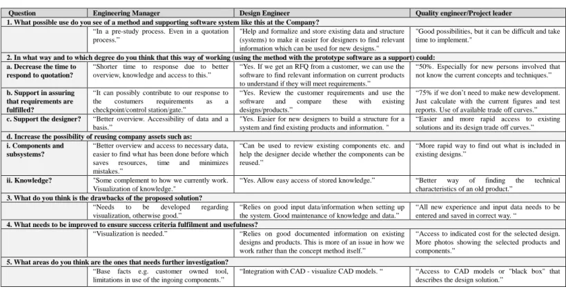
Evaluation
In order to make an evaluation of the presented software application and method, the DPM has been presented, discussed and demonstrated for potential users at the case company. The three company representatives that took part in the evaluation had the following professions: Engineering Manager, who also has the main responsibility of design methodology development at the company. A design engineer who has the main responsibility of preparing quotes and designing the presented seat support system. A quality engineer who has formally been one of the main project leaders for preparing quotes and design of the seat support system. The three respondents represent three potential users of the tool at different hierarchical levels in the organization. One of the respondents answers have been translated from Swedish to English and company names have been removed. The questionnaire contained questions mainly based on the Success Criteria that was identified together with the company in the beginning of the project and how well the presented method and software support fulfilled those. The questionnaires, that was filled in individually, is summarized in Table 1.
Question Engineering Manager Design Engineer Quality engineer/Project leader 1. What possible use do you see of a method and supporting software system like this at the Company?
“In a pre-study process. Even in a quotation process.”
"Help and formalize and store existing data and structure (systems) to make it easier for designers to find relevant information which can be used for new designs."
"Good possibilities, but it can be difficult and take time to implement."
2. In what way and to which degree do you think that this way of working (using the method with the prototype software as a support) could: a. Decrease the time to
respond to quotation?
“Shorter time to response due to better overview, knowledge and access to this.”
“Yes. If we get an RFQ from a customer, we can use the software to find relevant information on current products to understand if they will meet requirements.”
“50%. Especially for new persons involved that not know the current concepts and techniques.”
b. Support in assuring that requirements are fulfilled?
“It can possibly contribute to our response to the costumers requirements as a checkpoint/control station/gate.”
“Yes. Review the customer requirements and use the software and compare these with existing designs/products.”
“75% if we don’t need to make new development. Just calculate with the current figures and test reports. Use of available trade off curves.”
c. Support the designer? “Better overview. Accessibility of data and a basis.”
"Yes. Easier for new designers to build a structure for a system and find existing products and information. "
“Easier and more rapid access to existing solutions and its design trade off curves.”
d. Increase the possibility of reusing company assets such as: i. Components and
subsystems?
“Better overview and access to necessary data, easier to find what has been done before which saves resources, time and minimizes mistakes.”
“Can be used to review existing components etc. and help the designer decide whether the components can be reused.”
“More rapid way to find out what is included in existing designs.”
ii. Knowledge? "Some complement to how we currently work. Visualization of knowledge."
“Yes. Allow easy access of stored knowledge.” “Better way of finding the technical characteristics of an old product.”
3. What do you think is the drawbacks of the proposed solution?
“Needs to be developed regarding visualization, otherwise good.”
“Relies on good input data/information when setting up the system. Good maintenance of knowledge and data.”
“All new experience and input data needs to be entered and saved in correct way. “
4. What needs to be improved to ensure success criteria fulfilment and usefulness?
“Visualization is needed.” “Relies on good documented information on existing designs and products. This is more of an issue in how we work rather than the concept method itself.”
“Access to indicated cost for the selected design. More photos showing the selected products and components.”
5. What areas do you think are the ones that needs further investigation? “Base facts e.g. customer owned tool,
limitations in use of the ingoing components.”
“Integration with CAD - visualize CAD models. “ “Access to CAD models or "black box" that describes the design solution.”
CREATING AN ABILITY TO MASTER FLUCTUATING REQUIREMENTS
One way to use a platform approach is to preplan variants and optimize the platform design for high commonality and high distinctiveness. This would however increase the risk of losing projects to another supplier that agrees to a higher level of customization due to that the predeveloped variants does not comply with the customer requirements. This approach would correspond to trying to foresee future requirements and interfaces which in turn could increase the vulnerability of the business. The DP approach is instead about acknowledge fluctuations, realizing that change will happen and to use a flexible platform approach, that off course will not develop the variant for you, but will let you be more equipped when offering a higher level of customization.
Both the Expansion and Execution step is of great importance in the mission of creating an ability to master fluctuating requirements. Expansion is about being proactive during product development by finding best practice methods and being zealous when creating the descriptions that during execution of the DP is used. It is in this stage that the platform evolves by the addition of new knowledge and design descriptions. Execution is the step when a need for an ability to master and manage fluctuating requirements arises. Master in the sense of being responsive to fluctuations and not in the sense that requirements can be affected. It is about having a way to adapt to the reality of fluctuating requirements. The execution step aids development loop backs when iterations needs to be made. In the case when a design has been made, been tested by the customer and been judged to not comply with some requirements, the DPM can be used again for browsing for DEs. Where there formally was a component that could be reused, the new situation might demand an increase of performance which the current component does not meet. In these cases the generic product items can again be searched for guidance in the construction of the desired component or modification of a specific attribute. The model is again instantiated and all of the used DEs are encapsulated in the instance object that is saved for future reuse purposes.
DISCUSSION
If seeing to the literature, this research has struck a spot where not much has been explored in terms of supporting the designers and decision makers to draw the benefits from a more abstract definition of a platform. The goal of the research is to make companies acting as suppliers, developing highly customized products, more responsive to changing and fluctuating requirements at the same time improving both speed and accuracy in the quotation process and subsequent product development process. This is of course a goal that is of more long term character. However the result of this specific study points in that direction if looking to the evaluation. The aim of this paper was to explore how a platform approach could be applied and if a method and software tool could be designed to support the platform approach. This has been accomplished
within the scope of this paper. However, questions always remain regarding the level of generalizability of the model and proposed software support. The DP model has been developed within an overarching project including four companies with similar issues, which strengthens the level of generalizability.
The outcome of the evaluation show good results and fulfillment of success criteria in a qualitative manner. Areas of improvement are mostly directed towards the software application prototype in terms of visualization and the need for system maintenance. However the functionality that realizes the platform approach receives good marks. The reading of spreadsheet files is time consuming and will in the future force the development of the application towards a database solution instead. Some limitations can be mentioned: The presented model is intended to serve industrial companies developing highly customized products and systems in a B2B environment. The model and support tool requires that knowledge have been modelled in order for the knowledge to be extracted in the execution stage. When used in a company the usage of the tool requires that the users are zealous while documenting the developed knowledge and information. The system will also require maintenance to make sure that the information in the system is up to date and valid. The implementation of the tool need to come further in order to judge the scalability of the model as more descriptions populate the application.
CONCLUSIONS AND FUTURE WORK
In this work a platform approach directed to suppliers of highly customized systems is presented as well as its realization in a prototype software application called the Design Platform Manager. The software application presented has been developed in close collaboration with a supplier active in the automotive industry. The platform approach and software tool aids the company to describe not only finished designs and how they relate to a generic design, but also e.g. methods, task descriptions, constraints and design rules. These descriptions, called Design Elements aids in receiving a view of how and what that can be reused regarding company assets. The platform model is allowed to evolve over time and its definition supports the studied company to be more adaptable to fluctuating requirements. Success criteria have been identified and used to create a questionnaire in order to evaluate the result by company representatives. The evaluation show good result in terms of increasing the level of reuse, speed and accuracy during quotation and design engineer support. Future work regarding both the platform approach and support tool is to develop a process view to aid the designers in what order to perform and use the DEs. To reach files saved in the company PDM system is also a necessity. To strengthen the generalizability more validation using quantifiable data is going to be conducted as well as applying the model in other cases.
ACKNOWLEDGMENTS
The authors would like to express a lot of gratitude to the case company for invaluable information and time. Thank you
also to the Swedish Agency of Innovation Systems (VINNOVA) for funding the project.
REFERENCES
[1] Högman, U., Bergsjö, D., Anemo, M., and Persson, H., "Exploring the potential of applying a platform formulation at supplier level-The case of Volvo Aero Corporation," Proc. DS 58-4: Proceedings of ICED 09, the 17th International Conference on Engineering Design, Vol. 4, Product and Systems Design, Palo Alto, CA, USA, 24.-27.08. 2009.
[2] Blessing, L. T., and Chakrabarti, A., 2009, DRM, a design research methodology, Springer.
[3] Hansen, B. L., 2003, "Development of industrial variant specification systems," Technical University of DenmarkDanmarks Tekniske Universitet, Department of Management EngineeringInstitut for Planlægning, Innovation og Ledelse.
[4] Jiao, J. R., and Chen, C.-H., 2006, "Customer requirement management in product development: a review of research issues," Concurrent Engineering, 14(3), pp. 173-185. [5] Hvam, L., Pape, S., and Nielsen, M. K., 2006, "Improving
the quotation process with product configuration," Computers in Industry, 57(7), pp. 607-621.
[6] Almefelt, L., Berglund, F., Nilsson, P., and Malmqvist, J., 2006, "Requirements management in practice: findings from an empirical study in the automotive industry," Research in engineering design, 17(3), pp. 113-134. [7] Andersson, F., 2003, "The Dynamics of Requirements and
Product Concept Management A Product Modelling Approach."
[8] Meyer, M. H., A. P. Lehnerd, 1997, The power of product platforms - Building value and cost leadership, The Free Press, New York.
[9] Robertson, D., K Ulrich, 1998, "Planning for product platform," Sloan management review, pp. 19-31. [10] Johannesson, H., 2014, "Emphasizing reuse of
generic assets through integrated product and production system development platforms," Advances in product family and product platform design: Methods & application, pp. 119-146.
[11] Simpson, T. W., 2004, "Product platform design and customization: status and promise," Artificial Intelligence for Engineering Design, Analysis and Manufacturing, 18(1), pp. 3-20.
[12] Berglund, F., Bergsjö, D., Högman, U., and Khadke, K., "Platform strategies for a supplier in the aircraft engine industry," Proc. ASME 2008 International Design Engineering Technical Conferences and Computers and Information in Engineering Conference, American Society of Mechanical Engineers, pp. 55-66.
[13] André, S., Stolt, R., Elgh, F., Johansson, J., and Poorkiany,M., 2014, "Managing Fluctuating Requirements by Platforms Defined in the Interface Between Technology and Product Development," The 21st
ISPE International Conference on Concurrent Engineering :, IOS Press.
[14] Cooper, R. G., 2006, "Managing technology development projects," Research Technology Management; Nov/Dec, pp. 23-31.
[15] Guðlaugsson, T. V., Ravn, P. M., Mortensen, N. H., and Sarban, R., 2014, "Front-end conceptual platform modeling," Concurrent Engineering, 22(4), pp. 267-276. [16] Claesson, A., Rosvall, B. r., and Johannesson, H.,
"Capturing design knowledge of robust designs using configurable components," Proc. ASME 2005 International Design Engineering Technical Conferences and Computers and Information in Engineering Conference, American Society of Mechanical Engineers, pp. 423-434.
[17] Levandowski, C., Raudberget, D., and Johannesson, H., "Set-Based Concurrent Engineering for Early Phases in Platform Development," Proc. The 21st ISPE International Conference on Concurrent Engineering.
[18] Bruun, H. P. L., Mortensen, N. H., and Harlau, U., 2013, "PLM support for development of modular product families," International conference on engineering design, ICED1319-22 August 2013, Sungkyunkwan Uneversity, Seoul, Korea.
[19] Hölttä-Otto, K., Chiriac, N., Lysy, D., and Suh, E. S., 2014, "Architectural decomposition: the role of granularity and decomposition viewpoint," Advances in Product Family and Product Platform Design, Springer, pp. 221-243.
[20] Baxter, D., Gao, J., Case, K., Harding, J., Young, B., Cochrane, S., and Dani, S., 2007, "An engineering design knowledge reuse methodology using process modelling," Research in Engineering Design, 18(1), pp. 37-48.
[21] Stokes, M., 2001, Managing engineering knowledge: MOKA: methodology for knowledge based engineering applications, Professional Engineering Publ.
[22] Regli, W. C., Hu, X., Atwood, M., and Sun, W., 2000, "A survey of design rationale systems: approaches, representation, capture and retrieval," Engineering with computers, 16(3-4), pp. 209-235.
[23] Elgh, F., and Poorkiany, M., "Supporting traceability of design rationale in an automated engineer-to-order business model," Proc. DS 70: Proceedings of DESIGN 2012, the 12th International Design Conference, Dubrovnik, Croatia.
[24] Huang, Y., Jiang, Z., Liu, L., Song, B., and Han, L., 2015, "Building a knowledge map model situated in product design," International Journal of Information Technology and Management, 14(1), pp. 76-94.
[25] Elgh, F., "Supporting Quotation Preparation by Process and Knowledge Modeling–Principles and Concepts for Automation" Proc. ASME 2011 International Design Engineering Technical Conferences and Computers and Information in Engineering Conference, American Society of Mechanical Engineers, pp. 749-758.