Robot manipulation based on Leap Motion
- For small and medium sized enterprises
Ulrica Agell
DEPARTMENT OF ENGINEERING SCIENCE
A THESIS SUBMITTED TO THE DEPARTMENT OF ENGINEERING SCIENCE
IN PARTIAL FULFILMENT OF THE REQUIREMENTS FOR THE DEGREE OF
MASTER OF SCIENCE WITH SPECIALIZATION IN ROBOTICS
AT UNIVERSITY WEST
2016
Date: June 28, 2016
Author: Ulrica Agell
Examiner: Patrik Broberg, PTC
Advisor: XiaoXiao Zhang, PTC
Programme: Master Programme in Robotics
Main field of study: Automation with a specialization in industrial robotics
Credits: 60 Higher Education credits (see the course syllabus)
Keywords: Gesture recognition, SME, Leap Motion, robot manipulation
Template: University West, IV-Master 2.7
Publisher: University West, Department of Engineering Science S-461 86 Trollhättan, SWEDEN
Summary
On-line programming of industrial robots is time consuming and requires experience in ro-bot programming. Due to this fact, small and medium sized enterprises are reserved about the implementation of robots in production. Ongoing research in the field is focused on finding more intuitive interfaces and methods for programming to make the interaction with robots more natural and intuitive. This master thesis presents a method for manipulation of industrial robots utilizing an external device other than the traditional teach pendant. The base of the method is a PC application which handles the program logic and the communi-cation between an external device and an ABB robot. The program logic is designed to be modular in order to allow customization of the method, both in terms of its functions and the type of external device that is used for the method.
Since gestures are one of the most common forms of communication between humans, it is interesting to investigate gestures for the purpose to make manipulation of industrial robots more intuitive. Therefore, a Leap Motion controller is presented as an example of an external device which could be used as an alternative to the teach pendant. The Leap Motion controller is specialised on hand and finger position tracking with both good absolute accu-racy and precision. Further, its associated Software Development Kit (SDK) has the capa-bilities which are required to enable implementation of a teach pendants most fundamental functionalities. Results obtained by a user test show that the developed application is both easy and fast to use but has poor robustness.
Preface
This work was performed as a master thesis in robotics and automation at University West in Trollhättan. The work was performed during ten weeks of spring 2016 at Production Technology Center, Trollhättan. The author would like to thank her supervisor Xiaoxiao Zhang for valuable support through the project. She also wants to thank Svante Augustsson for help with the report and the robot station. Further, thanks to Mattias Bennulf for help with programming and handling of the ABB PC SDK. Finally, a thanks to Nithin Ramesh and Kewal Shaholia for their help with documenting the work.
Affirmation
This master degree report, Robot manipulation based on Leap Motion – For small and medium sized enterprises, was written as part of the master degree work needed to obtain a Master of Science with specialization in Robotics degree at University West. All material in this report, that is not my own, is clearly identified and used in an appropriate and correct way. The main part of the work included in this degree project has not previously been pub-lished or used for obtaining another degree.
28/06-2016 __________________________________________ __________
Contents
Preface
SUMMARY ... III PREFACE ... IV AFFIRMATION ... V CONTENTS ... VIMain Chapters
1 INTRODUCTION ... 1 1.1 AIM ... 2 2 BACKGROUND ... 3 2.1 INDUSTRIAL ROBOT ... 3 2.2 TEACH PENDANT ... 3 2.4 GESTURE RECOGNITION ... 52.5 LEAP MOTION CONTROLLER ... 6
2.6 APPLICATION PROGRAMMING INTERFACE ... 7
2.7 ABBSOFTWARE DEVELOPMENT KIT ... 8
2.8 ABBPCSOFTWARE DEVELOPMENT KIT ... 8
2.9 LEAP MOTION SOFTWARE DEVELOPMENT KIT ... 9
3 METHOD ... 11 3.1 LITERATURE STUDY ... 11 3.2 PROGRAMMING/DESIGN ... 11 3.3 SIMULATION ... 11 3.4 EXPERIMENTS/TESTING ... 11 4 WORK ... 12 4.1 DEVELOPMENT ENVIRONMENT... 12
4.2 USER-INTERFACE FEATURES ... 12
4.3 PROGRAM FUNCTIONALITY ... 17
4.4 PROGRAM ... 18
4.5 USER TEST ... 20
4.6 CUSTOMIZATION OF THE METHOD ... 21
5 DISCUSSION/RESULT... 23
5.1 RESULT OF USER TEST ... 23
5.2 ABBPCSDK ... 25
5.3 LEAP MOTION ... 26
6 CONCLUSION ... 28
1 Introduction
The overall usage and the number of applications of robots are continuously increasing. Still, the most extensive usage is within the industrial context [1]. Due to the ongoing globalisation and the growing demand for customised products, the need for flexible and reconfigurable automation systems that are easily adapted to changing production requirements is increasing. One of the difficulties in this context is that programming of industrial robots is still a demanding task [2]. Because of the complexity in program-ming, small and medium sized enterprises (SMEs) have difficulties to utilize the advantages of industrial robots. SMEs stand for 99 % of all the businesses in EU and are defined as companies with an employee headcount between 10 and 250 employees and a turnover between 2 and 50 million euro [3]. SMEs have neither the resources, nor the knowledge to program and consequently find it difficult to compete on the global market [4].
Considering the complexity of robot programming and the limited economic feasi-bility to hire external help, SMEs do not get access to the benefits of automation by the usage of robots. To make the usage of robots more accessible for inexperienced users, the interface and the way to manipulate the robot have to be improved. Ongoing sci-entific research in the field is focusing to investigate easier and more intuitive methods for programming [5]. Techniques which can be seen today in our daily lives, such as phones, TV and computer games, which use natural user interfaces, are a source of inspiration for research in the field in order to make programming manageable for eve-ryone.
Today, several off-the-shelf products are used or investigated for future usage with the purpose to ease the interaction with different types of robots. These devices can be divided into two categories, devices that enable control in 2D, e.g. keyboard, computer mice, dial and devices which enable control in 3D, e.g. joystick, Nintendo Wii Control-ler, Leap Motion ControlControl-ler, Microsoft Kinect. However, in the context of industrial robots, the main objective is to find a technique that can challenge the weaknesses of the traditional teach pendant, e.g. the limited working area because of the wire and the lack of intuitiveness. For an industrial robot, with six degrees of freedom, the most appropriate would be to use a technique which enables control in 3D. Due to an in-creased access to low-cost depth sensors on the market, non-contact devices have had increased attention in recent years. The purpose of investigating the usefulness of these devices is to make the interaction with robots more natural and intuitive [14]. Examples of non-contact based devices which, are interesting for this application, is Microsoft Kinect and the Leap Motion controller.
The Leap Motion controller is a device specialised for hand and finger position tracking [6]. Research shows that it has both very good absolute accuracy and repeata-bility but a limited sensing range [7] [8] [2]. The strengths of Microsoft Kinect are the large sensing range (~0.4 m to ~5 m) [9], its ability to track and provide skeleton data of a whole human body and recognise gestures [10]. At a close distance, it is also able to recognise facial expressions [10]. However, the amount of noise in the captured data is increasing with the distance to the sensor [9]. Consequently, tracking of a whole body, which requires a certain distance from the sensor, results in less accurate data. The
Robot manipulation based on Leap Motion - Introduction
choice of device for gesture recognition depends on the intended application. For ap-plications where the interpretation of the gestures is more critical than the exact posi-tion data of the tracked object, in scenarios for example when bigger parts of the human body needs to be tracked or simpler gestures like an open/closed hand, the Kinect sensor is good enough. In applications where the quality of the data is of more im-portance, when accuracy, repeatability and speed is a critical factor and the sensing range do not need to be larger than 25–600 mm above it, the Leap Motion controller is a better choice.
1.1 Aim
The aim of the thesis work is to develop a robot manipulation method suitable for SMEs which utilizes another device than the traditional teach pendant as a user inter-face. The method shall be modular in terms of the choice of device, which means that it shall be possible to customise the resulting application to the end user’s needs. The method shall be presented through an example where the Leap Motion controller is used as part of the user interface. The Leap Motion data, in form of captured gestures, will be used as input for the application and converted into commands to the robot as output. In order to accomplish this, the communication between the Leap Motion con-troller, a PC and an industrial ABB robot have to be investigated. The Leap Motion SDK and the ABB PC SDK have to be studied in order to understand its capabilities. Communication will be enabled through the setup of a development environment, us-ing Microsoft Visual Studio. Finally, the focus will be set to the design of the method. The method shall be intuitive enough to suit inexperienced users and should be appro-priate to use for simple tasks such as recording of robot targets, pick and place tasks and nailing tasks.
2 Background
2.1 Industrial Robot
An industrial robot is, according to ISO 8373:2012, defined as an automatically con-trolled manipulator which is capable of performing a variety of tasks within industrial automation applications. The manipulator can either be fixed in one place or be mobile and consists of a chain of links which can rotate or slide relative to one another. The manipulator shall be programmable and reprogrammable in three or more axes. Within the industrial context, fixed robots are often used to replace human workers in tasks which are tedious, monotonous, hazardous or when the task demands high precision [11]. Examples of applications where robots are used are pick and place tasks, moving, paint spraying, welding, cutting and sanding [12]. An industrial robot can increase the productivity, quality and safety of a task because it can work continuously without fa-tigue, have repeatable precision and has higher absolute accuracy than humans. The industrial robot can e.g. be equipped with one or several vision or force sensors and use the information for controlling and improving the quality of the process. This increases the performance in a way, which is not possible with a human worker [11].
An industrial robot consists of the robot arm/manipulator arm, an end-effector, a control unit and a power supply. The arm is built by a series of links connected together through joints. The joints are either revolute or prismatic. The end-effector is attached to the end of the arm. Normally an industrial robot has six joints which consequently determine the number of degrees of freedom (DOF) to six which is necessary to be able to reach an arbitrary point, within the working range, in 3D space. A rigid body in 3D space has six DOF, three for position and three for orientation [11]. The control unit consists of several functions which control the robots work and can obtain and process information from e.g. external sensors in real-time. It supervises that instruc-tions and logic are executed in the correct way and regulates the movement of the arm and end-effector. The control unit also enables the robot to communicate with other systems, machines, processes, robots and Ethernet [13].
2.2 Teach pendant
Today, the most common human machine interface (HMI) for manipulating a robot arm is a teach pendant. The traditional teach pendant is a hand held device which can control movement and velocity of the robot arm, the rotation of all six joints, the posi-tion and pose of the end effector in six DOFs and control of input/output communi-cation [12]. An example of the main parts, which a teach pendant consists of, is a touch screen, a joystick or hard buttons for motion control, an enabling device/“dead man” switch, an emergency button, a USB port, hard buttons and connector. The device can be used to program and jog the robot and for running programs in manual mode. Jog-ging is when the manipulator arm is moved by use of the joystick or hard buttons, which enables control of the robot in 3D. During jogging, it is possible to create or modify robot targets which can be recorded by the robot controller for later usage in programs. The teach pendant provided by ABB, called Flex Pendant, provides setting of speed (move faster, move slower), direction (x, y, z), rotation of axis (axis 1-3 or axis 4-6)
Robot manipulation based on Leap Motion - Background
through the joystick. Through the selection of motion mode, the motion of the TCP and the rotation of the axis can be controlled in different ways. In linear mode, the tool centre point (TCP) moves linearly according to the chosen coordinate system (world-, base-, work object- or tool coordinate system). In the axis by axis mode, one axis is rotated at the time. Either axis 1-3 or axis 4-6 can be selected and rotation of the chosen axis is then controlled by different directions of the joystick. In reorient mode, the manipulator arm is rotated around the TCP, this is generally done in order to evaluate the tool definition. The touch screen provides the user with a lot of different functions and information, e.g. information about the exact position of the TCP according to the chosen coordinate system [14]. Even if researchers has put a lot of effort in order to make the manipulation of the robot arm easier, e.g. introduced touch screens and joy-sticks instead of hard buttons, the intuitiveness is not sufficient enough and the manip-ulation of the robot arm still needs experienced operators [12].
2.3 Robot programming
According to the definition, an industrial robot shall be programmable and reprogram-mable [11]. Programming is the method used to describe the desired robot motions which the robot shall follow during task execution. A program can consist of different routines which shall be executed in a certain order or when a specific condition becomes true. A program can also include instructions for input and output control signals and other logic operations. Today, the two main methods for programming of industrial robots are on-line programming and off-line programming.
In on-line programming, the programming is done at the place of the physical robot system [13]. The teach pendant is used to manually jog the robot’s end-effector to de-sired points with a specific orientation and at the same time, the robot controller is recording the robot configurations. A path is then formed by commanding the robot to pass through the defined points with the tool centre point of the end-effector [5]. Programming in the actual environment of the robot, with the equipment which is meant to be used during production, minimises errors, gives direct feedback of the re-sult of the programming and a good overview of the functionality of the program. Fur-ther advantages are that the programming can be done by the operator, which has knowledge of the production process and is used to the equipment [13]. On the other hand, most teach pendants used today are still not easy and intuitive enough to be used by an operator without special robot programming knowledge [1]. Further, on-line pro-gramming is time consuming [5] and during the propro-gramming the robot cannot be used in the production. The relevance of this disadvantage grows when the robot needs to be reprogrammed often. In production systems which produce low volumes but with frequent product changes, the costs of the production down time could be the critical factor which makes use of robots not feasible [13]. On the other hand, for simpler production systems where product specifications are not changed, the method is a good choice because it is efficient, cost-effective and has a low initial cost. Therefore, the method is commonly used in the industry for uncomplicated tasks and for workpieces with simple geometry. However, when the complexity of work pieces and tasks in-creases, the applicability of this method decreases [5].
Off-line programming is widely used within automation systems which produce large volumes. With large volumes, this method is both efficient and cost-effective, but initially it can involve a large investment because of the expertise that is needed to per-form the programming. The method makes it possible to program and simulate the task
by the use of a computer and an off-line programming software, e.g. ABB Robot Studio, before the program is downloaded to the robot. A 3D model of the robot cell and 3D CAD models of the workpieces can be used within the software, which makes this method especially accurate and suitable for complex work piece geometries. Programs and reprogramming can be done without interfering with the ongoing production, which minimises the down time of the robot. However, off-line programming requires advanced programming skills. Generally, software engineers are doing the program-ming instead of the operator, which usually do not have the programprogram-ming knowledge that is needed. Despite the obvious advantage of off-line programming, the method is rarely used by SMEs because of the involved costs which cannot be justified when the production volume is low.
In order to find programming methods for industrial robots which are more suitable for SMEs, academic researchers are trying to find new solutions. For on-line program-ming, the focus is set to sensors and control technologies, which can support the oper-ator in more complex programming tasks. Researchers are also looking for a way to reduce the cost of off-line programming by e.g. the use of open source off-line pro-gramming solutions and making off-line propro-gramming more flexible and interactive by a combination of the mentioned programming methods and augmented reality [5].
2.4 Gesture recognition
One method to make the interaction and communication with computers more natural and intuitive is to use gesture recognition [15]. Of the communication between humans, the two most common forms are hand gestures and voice. However, in the industrial context, gesture communication is preferred due to the industrial environment which can imply loud background noise and therefore limit the use of voice communication [10]. Gestures have been an interesting research subject within the human computer interaction (HCI) field for the last few decades. Gesture recognition refers to the pro-cess where gestures are converted into commands. The research aim of gesture recog-nition techniques is to develop an accurate, efficient and robust system that identifies gestures as input and converts the data into commands as output [15]. One focus area of gestures is hand gestures. Hand gestures can be divided into two sub-categories, the first category concerns static and dynamic gestures and the second category classifies the gestures based on the meaning e.g. giving thumb up instead of saying OK or show-ing direction with the hand instead of usshow-ing words. Static hand gestures are time inde-pendent and involves orientation, shape, flex angle of fingers and the relative position to the body. Dynamic hand gestures are time dependent and involves orientation, shape, flex angle of fingers, trajectory, speed and scale [16]. Today, gesture recognition is widely used to transmit information within applications such as computer games, machine control and as a substitute for the computer mouse [17]. However, there are still unresolved challenges in the field, which needs further research. One of the main challenges is the wide span of existing gestures. The research area of gesture recognition can be divided into two parts, contact based and non-contact based gesture recognition [15].
2.4.1 Contact based gesture recognition
The contact based aspect refers to techniques where the interaction between user and interface involves physical contact. Devices that are used for contact based gesture recognition can be classified as mechanical, haptic and inertial [15]. Example of devices
Robot manipulation based on Leap Motion - Background
that utilizes the contact based techniques for gesture recognition are hand held accel-erometer based input devices and gloves which can track the human hand in real time [10]. The use of wearable devices is often restricted within the industrial context because it can increase cycle time to put them on and off and may involve additional mainte-nance which implies extra costs [10]. Examples of off-the-shelf products are the Nin-tendo Wii-Remote and multi-touch screens as the one used for Apple iPhone [15].
2.4.2 Non-contact based gesture recognition
The non-contact aspect refers to solutions which utilise magnetic, ultrasonic or vision based techniques. However, this thesis work is mainly focused on vision based non-contact gesture recognition, which is based on one or several cameras capturing a video sequence of hand/hands. Together with the cameras, hand markers can be used to evaluate the position of the hands in 3D space [15]. Vision based gesture recognition has the advantage over both hand held devices and wearable devices, that it does not interfere with the movements of the user [10]. In recent years, 3D sensors with creased robustness and accuracy have been developed. For gesture recognition in in-dustrial applications, the accuracy of the sensor is an especially interesting and challeng-ing subject [7]. 3D sensors can be divided in three sub-categories based on their func-tional principle: structured light, stereo vision and time of flight. Using structured light means that the deformation of a known pattern projected to an unknown surface is analysed in order to determine the depth and the surface of an object. Time of flight refers to the technique where the distance to an object is determined by the time it takes for the laser beams to travel back to the sensor. Stereo vision refers to the technique where two 2D cameras are used to determine the depth in the image by identification of corresponding points in both 2D images. For stereo vison, the extrinsic parameters, which signify the transformation between the 3D world coordinate system to the 3D camera coordinate system have to be known [7].
2.5 Leap Motion Controller
The Leap Motion controller is a small device used for hand and finger position tracking developed by Leap Motion, Inc. [18]. The controller is equipped with two infrared light cameras and three infrared emitters and can therefore be categorized as a stereo vision based device [14]. By a combination of the sensor data and a predefined model of the human hand, tracking of complicated gestures is possible [18]. The device is connected to a PC through a USB bus and a Leap Motion software is used on the PC, which can be downloaded from the website [18]. The controller data can be assessed through the API provided by the Leap Motion SDK which supports several programming languages e.g. C++, C#, Java, Unity (V2 and Orion), JavaScript, Unreal Engine, Objective-C and Python [18] [19].
The controller has a spherical conic sensing space totally consisting of 8 cubic feet with a 150 º view [18] where the effective sensing range is between ~ 25 – 600 mm above it [19]. The system sends and analyses data with a frequency of 200 frames per second [20] [18]. Weichert et al. [14] investigate the accuracy and the repeatability of the sensor (available version 2013) through an experiment using an industrial robot (KUKA Robot KR 125/3) with a reference pen with the pen tip defined as the tool centre point of the robot end-effector. During the experiment, the accuracy and repeatability of the sensor were tested in both static and dynamic situations. Accuracy refers to the sensor’s
ability to determine a specific position in 3D space and repeatability refers to the sen-sor’s ability to detect that specific position over and over again. The reference pen tip was tracked by both the Leap Motion controller and the industrial robot at the same time. The industrial robot has the ability to achieve repeatable accuracy <0.2 mm which makes it suitable to use as a reference for evaluation of the Leap Motion controller capabilities. The experiment for static situation resulted in a deviation of <0.2mm be-tween the desired 3D point and the measured point. The dynamic situation resulted in <2.5mm and the repeatability value with an average of <0.17mm.
Guna et al., [19], did further evaluation of the controller’s accuracy and precision. In contrast to the observed results of Weichert et al. the authors in this study had a problem to get the controller to track a sharp object and had to use a “hand-like” object for the static tracking. The conclusion was that the algorithms of the controller had been updated. Experiments showed that the accuracy of the sensor was lower when the tracked object was moving away from the controller. Significant drop in accuracy was observed when the tracked object was more than 250 mm above the sensor.
G. Du and P. Zhang, [2] states that one single Leap Motion controller is not enough for applications aiming for manipulation of industrial robots. The authors point out weaknesses as the narrow working space, weak stability, nonlinearity, white noise and reduced accuracy when hands are in certain orientation e.g. palm is pointing upwards more than 45º. The results obtained by Guna et al. [19], which showed a decreased accuracy while moving away from the sensor, emphasises with the statement of the controllers limited effective sensing space. The experiments also showed inconsistency in the sampling frequency in both the static and the dynamic scenario. These findings indicate that the controller could have synchronisation problem with other real-time systems. To overcome this weakness G. Du and P. Zhang [2], used five Leap Motion controllers. With a tracking system consisting of five controllers, the work space of one single controller is overlapped by another. This means that several controllers simulta-neously determine the position of the human hand.
2.6 Application Programming Interface
In operating systems, Application Programming Interfaces (API) has an important role. API is the description for how programs/software’s communicates with other pro-grams/software’s in order to access data or make another program/software to perform a task. For example, if a program requests access to data or to a function owned by another program, the asking program has to do the request in a standardised way. This standardised request is the API, which is defined by the program that owns the data. In the same way, developers can request access to data and functions owned by another program by calling the program in the application code according to the spec-ifications of the API. The API allows the developer to use functions and data in a pre-defined, but in some sense, restricted way. By providing assessable and easy to use APIs, the owning company of the software encourage developers to create new applications for the software [18].
Some companies provide Software Development Kits (SDK) together with the de-vice and the software in order to enable development of new applications for the dede-vice. A SDK works as an interface between the device and the application and contains a high level API that makes it possible to utilise the software’s abilities without the han-dling of raw data. Both Leap Motion and ABB provide SDKs compatible with Mi-crosoft Visual Studio.
Robot manipulation based on Leap Motion - Background
2.7 ABB Software Development Kit
ABB provides several different SDKs, the PC SDK, the FlexPendant SDK and the RobotStudio SDK. All SDKs has the purpose to ease development of applications related to the use of ABB robots. The RobotStudio SDK is used for creating add-ins for RobotStudio which adds functionality to the software tool. The PC SDK and the FlexPendant SDK are both intended for controller applications. The reason for two separated SDKs, which should not be used together, is that a controller application is platform dependent. The PC SDK is meant to be used for PC based applications and the FlexPendant SDK is meant for Flex Pendant based applications.
2.8 ABB PC Software Development Kit
The PC SDK is intended to use for development of PC based applications focused on customiasing the user interface for ABB IRC5 controllers. The PC SDK can be used for communication with either a virtual IRC5 controller through RobotStudio, a real IRC5 controller through a direct network connection or through the controller service port. RobotStudio is a software tool used for both offline-, online programming and simulation. The tool is based on the VirtualRobot™ Technology, which is the same software the real controller runs on. The advantage with a virtual controller in Robot-Studio, is that the developer can test and debug the application in a completely virtual environment during the development phase. Except the network connection needed between the real controller and the PC, the only additional requirement for setup with a real controller is that the RobotWare used on the controller have the option PC In-terface. The version of PC SDK is developed for a certain RobotWare version. How-ever, it is compatible with different revisions of the version. If the RobotWare version is updated later on at a robot system, the PC SDK is in general compatible with a newer version but to be successful the runtime environment on the used PC have to be up-dated in order to match the RobotWare. Due to the network communication, that some parts of the API execute on a non-real-time operating system and the controller’s task priority, the response time and performance of the application can be affected when a real controller is used.
A PC application is a remote client, which makes it possible to access several con-trollers from the same location. One advantage with a remote client compared to a local client like a Teach Pendant application is that the memory resources and the processing power are not limiting factors. However, a remote client compared to a local client has certain restrictions regarding the access to the controller. One example of this is that the programmer must request write access to the rapid domain and the configuration domain before it is possible to give commands and change RAPID data. Further, the controller has to be set to automatic mode. The reason to this is that the resources of the controller can only be controlled by one client at a time. In manual mode, the Flex Pendant has write access and the remote client can only get access when an operator allows it through the Flex Pendant. In automatic mode, the first client, regardless if it is a local or remote client, has priority. In order to get write access, the application programmer has to request mastership of the controller in the program code.
The PC SDK uses the Microsoft .NET framework and Microsoft Visual Studio version 2013 or later. For application development, any programming language pro-vided by Visual Studio is possible to use. However, programming support and example
code, in the form of an application manual, a reference manual and an online commu-nity with a developer section, is only provided by ABB in the NET. programming lan-guages C Sharp and Visual Basic.
The PC SDK is entirely object-oriented and contains several class libraries, which are separated in different namespaces. The class libraries are organized in ten domains. The Discovery domain is utilized in order to scan the local network for controllers. In order to establish a connection from the application to a controller, a network scan is required. The scan provides information related to all controllers, both virtual and real, found on the network. In order to detect controllers outside the local network, the IP address of the controller has to be stated. The Configuration domain gives access to the configuration database and makes it possible to both read and write values to the configuration parameters. The Messaging domain enables interaction between the PC SDK application and a RAPID task and can e.g. be used in order to control the program flow of a RAPID program. The User Authorization system makes it possible to both read and demand authorization level for a user.
All the domains that give access to the functionality of the controller are organized in the Controller API. These domains are discussed below. The RAPID domain, which gives access to RAPID data in the robot system. With the use of the RAPID domain, it is possible to both read and change values in the RAPID program. However, it is not possible to create new RAPID data as e.g. robot targets, joint targets, paths, functions, variables, move instructions etc. For the moment, the controller API do not support the creation of a motion control algorithm for direct control of the servo system of the robot. Further, the SDK neither support the transfer of the axes values from a joint target to a robot target or the other way around.
The IO system domain makes it possible to read and write values to both digital and analogue signals and give notification when signal values changes but it does not support the creation of new signals. The file system domain makes it possible to delete, rename, save, load and create files. The Motion domain gives access to information regarding the mechanical units related to the robot system. The Event log domain gives access to event messages containing information regarding controller status, RAPID program execution etc. Further, controller events, which is a message from the control-ler that an event has occurred e.g. the value of a RAPID data has changed or the state of the controller has changed, runs on their own threads on the PC platform. This means that there is a risk that the user interface thread, in other words, the main thread is getting in conflict with the control event threads. This kind of conflicts can cause hangings of the PC and that the application stops responding. However, if a controller event should not be followed by an update of the user interface, this is not a problem [19].
2.9 Leap Motion Software Development Kit
The API included in the Leap Motion SDK contains several classes and methods, which makes it possible to track hands, fingers and other pointable objects such as tools. The predefined classes and methods can be utilised by the user in e.g. Microsoft Visual Stu-dio where the API then are used as a library. The controller can recognize four prede-fined gestures: circle gesture, swipe gesture, key tap gesture and screen tap gesture. By utilising the classes and functions within the API it is possible for the developer to create their own trackable gestures. The frame class provides access to all the tracked entities. It enables access to data regarding position, orientation, gestures and motions
Robot manipulation based on Leap Motion - Background
with update according to the Leap Motion frame rate. On each update interval a new frame is created. The frame class has a method that makes it possible to access the frame history buffer consisting of the 60 last frames. All the tracked entities get a unique ID, which is kept as long as the entity is tracked. Because of the history buffer and the unique ID it is possible to compare the change in e.g. position of an entity between different frames.
The largest class that the API contains is the hand class. The controller has an inner model of the human hand and compares the sensor data against the model. The model makes it possible for the controller to e.g. track the position of a finger even if the finger is not completely visible. The hand class provides tracking data, which describes the physical characteristics of the hand. This means that the controller can recognise if a hand is a right hand or a left hand and give the position of the palm centre point in millimetres with respect to the origin of the Leap Motion coordinate system. Further, the hand tracking data includes the orientation of the tracked hand, the posture of the hand in form of grab strength and pinch strength, the direction of the fingers, properties of a sphere that fits the posture of the hand and the speed and movement direction of the palm centre point in millimetres per second.
The API includes a vector class, which provides data describing points and direc-tions, and e.g. can give the pitch, yaw, roll angles respectively of the hand palm position. The vector class also has several math functions that make it possible to do common vector operations, calculate the dot product, get the length of a vector or calculate the distance between two points in three-dimensional space.
The matrix class enables several different matrix operations e.g. the transformation of a vector. An image class is also available, which provides raw sensor data and cali-bration grid for the cameras. This class is especially interesting for the development of applications using head-mounted display, augmented reality and computer vision [6].
3 Method
3.1 Literature study
The aim of the literature study was to get deeper knowledge in the field of robot ma-nipulation techniques, which is using vision based non-contact solutions. The study gave an understanding of the background of the robot manipulation field, the available solutions on the market today and the ongoing research in the field. The leap motion controller together with the Leap Motion SDK and the ABB PC SDK was studied in order to get an understanding of its capabilities. The obtained knowledge made it pos-sible to both understand the problem and to see pospos-sible solutions.
3.2 Programming/Design
The application is developed by using Microsoft Visual Studio as the platform. The code behind the application is written in the programming language C Sharp. The de-veloper environment enables communication between the Leap Motion software and the robot controller, both the virtual and the real version of the controller. The program has a modular structure in order to enable easy adjustments if the input device, in this work the Leap Motion controller, would be replaced with another kind of device.
3.3 Simulation
The ABB PC SDK provides the option for developers to use a virtual controller in RobotStudio or a real controller without any major adjustments in the setup. During the development phase of this application, the program has been continuously tested and evaluated by using RobotStudio. The choice to partly use a virtual controller instead of the real controller was done because of the limited accessibility of the real robot station and because iterative testing and debugging in RobotStudio would give a faster development process.
3.4 Experiments/testing
In order to evaluate the application and verify the results obtained from the tests per-formed in the virtual environment, tests on a real IRC5 controller was perper-formed at the end of the developing process. The application was evaluated in terms of robustness, intuitiveness and ease of use. All the application’s functionality have been recorded on video. Since one of the aims of the thesis work have been to create an application intu-itive enough to enable users without earlier experience in robot programming to per-form the programming, a part of the final testing was perper-formed as a user test. A group of students was asked to define the target points included in a pick and place task by using the developed application. After the test, the students were asked to answer a couple of specific questions and give their general thoughts about the application.
Robot manipulation based on Leap Motion - Work
4 Work
Today, the general method for manipulating an industrial robot is to use the teach pen-dant as the operator interface. However, there are reasons to investigate how well other devices can take on the role as the operator interface. One of the reasons is that there is a need for a method which makes manipulation of the robot easier for the user. Another reason is the need for a manipulation method, which can be customized for the end user’s specific needs. This section describes the developed method in general and in particular, the design and functionalities of the developed application as an ex-ample of how an industrial robot can be manipulated through a manipulation method other than the flex pendant.
The method implements the most fundamental functions of the flex pendant such as jog of the robot, creation of programs and program execution. It allows the user to select jog direction [x, y, z] and the TCP is then moved linearly according to the chosen coordinate system. Further, it allows rotation of the tool around the TCP, rotation of all six axes separately, modification, recording and deleting of robot targets.
4.1 Development environment
In order to enable manipulation of an industrial robot with gestures, a system was cre-ated. The system consists of three main components, a Leap Motion controller, a PC and an ABB robot with an IRC5 controller. During testing the ABB robot was replaced by a virtual IRC5 controller in RobotStudio 5.61. In the system, the Leap Motion con-troller is physically connected to the PC via USB port and the real IRC5 concon-troller is connected via an Ethernet cable. A PC application with Visual Studio 2013 as the code editing and compiler platform was created in order to set up the development environ-ment and the code behind the method. The PC application is then acting as the com-munication link between the Leap Motion controller and the IRC5 controller where the associated SDKs are used as libraries. The system takes input data from the Leap Mo-tion controller, which tracks gestures from the user and transforms it into data. The logic in the program code converts the data into commands for the robot. The output from the system is the resulting task, which the robot executes.
4.2 User-Interface Features
This section describes the used gestures, the thoughts about the Human Machine In-terface (HMI) design and the functionalities the developed application offers.
4.2.1 Gestures
The gestures chosen for the application is based on the level of robustness of the track-ing from the Leap Motion controller and the intuitiveness and comfortableness for the user. The comfortableness is important because even if the gestures are intuitive and detected by the Leap Motion controller, poorness in the ergonomic aspect will make the application unsuccessful. The Leap Motion sensing space has its centre point at 200 mm above the hardware see Figure 2. The size of the interaction box, where the user interacts with the Leap Motion controller, is depending on how high the centre point
is set. Holding the hand in a static position in front of the body will after some time cause tension and start to be uncomfortable for the user. Using the centre point of the palm to track the position of the hand allows the user to keep the hand in a relaxed posture. In order to secure the robustness of the application simple gestures, which the Leap Motion do not fail to recognise is important. The controller has the ability to recognise advanced gestures as e.g. circle gestures. However, during the testing the Leap Motion controller sometimes did not recognise the gesture directly. For this reason, more advanced gestures have been avoided in the developed application.
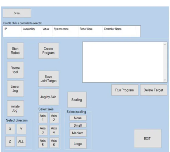
4.2.2 Human Machine Interface
A basic HMI, which can be seen in Figure 1, was created in order to allow the user to integrate with the application and make choices in those cases where gestures were considered a less intuitive interaction option. Cases that belongs to this category are e.g. selection of jogging mode, the command “run program”, “delete target”, selection of axis in “Axis by axis” etc. The scope of this project is not to deliver a application where the interaction between the user and the robot is entirely performed by gestures. That approach would be possible to integrate but would most likely not increase the user experience. Another example where the HMI will increase the user experience is when the user is performing the save target operation. For each time a target is saved, text box in the HMI updates with the target data for the specific target. Visualization of the data, as a result of a saving gesture, will most likely make the user confident in that the saving operation gave the expected result.
Robot manipulation based on Leap Motion - Work
4.2.3 Functionality
This section describes the functionality of the method from an end user perspective. It describes the different options that are available and what the user needs to do in order to get the desired result. If the users aim is to manipulate a robot with a real controller, this robot has to be set to automatic mode and the RAPID program has to be loaded into the controller before the application is started. If the user instead aims to manipu-late a virtual controller in RobotStudio, RobotStudio has to be open with a robot sta-tion, the RAPID program has to be loaded to the virtual controller and the simulation has to be set to run before the application is started.
The first step the user has to go through when starting the application before any manipulation of the robot is possible, is to scan the network for the controller. This is automatically done when the user press “Scan” on the first view that meets the user on the HMI. All controllers, real and virtual, which are connected to the network, will appear on the screen together with controller info related to each controller. The user selects the controller that is the target for the operation and the main view of the HMI will afterwards appear on the screen. To enable communication with the selected robot controller, the user has to press the “Start Robot” button. The user can then choose to change the axis values by “Axis by Axis, rotate the tool with “Rotation of Tool” or jog the robot by “Linear Jog” or “Imitate Jog”. If the user chooses to create a program by pressing “Create Program” in the HMI, it is possible to save the TCPs position during both jogging modes. If this option is not selected, no positions will be saved. It is pos-sible for the user to change freely between the different options while running the ap-plication.
4.2.4 Linear Jog
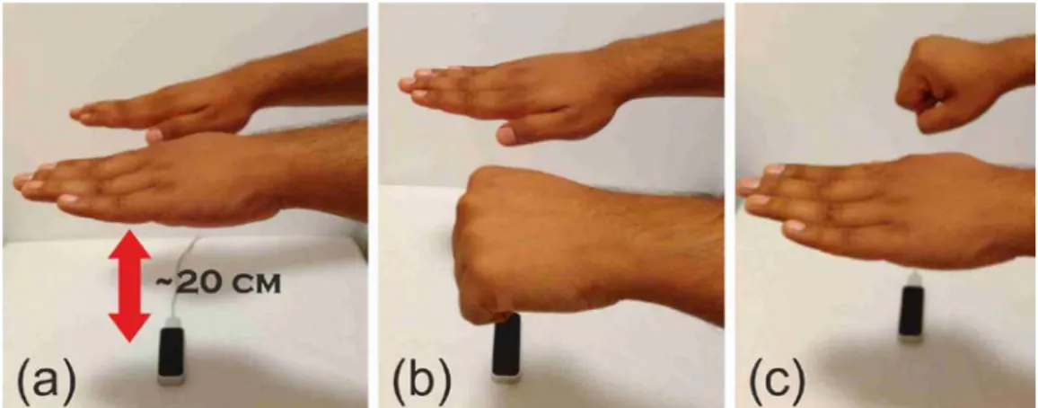
The user can jog the robot linear in x-direction, y-direction or z-direction. To enable Linear Jog the user has to define an initial position of the right hand palm. To do this, the user should keep both hands above the Leap Motion controller and close the left hand as visualised in Figure 2. This will save the centre point of the right hand palm as the initial position. Next, the user chooses which direction the robot should move in by moving the right hand in either x, y, z direction. When the centre point of the right hand palm is more than 100 mm away from the initial position, the robot starts to move in the chosen direction. While the robot is moving, the user can take the hands away from the controller. The robot will continue to move until the user gives a stop signal. The stop signal is given by closing the left hand regardless if the option “Create pro-gram” is selected or not. If this option is selected and the user wants to save a position, the user shall close the right hand above the sensor instead, see Figure 2. The position of the TCP will then be saved as a robot target. If the user wants to delete a saved target, this is done from the HMI by pressing “Delete Target”. To enable further jogging the user first have to close the left hand once to go back to the initiate state and then a new start position has to be declared by closing the left hand once again.
4.2.5 Imitate Jog
In Imitate Jog mode, the TCP of the tool follows the centre point of the right hand palm. The coordinates of the right hand palm centre point correspond to the robot TCP. There are four different options for Imitate Jog, which the user can select from the HMI: jog in x-direction, jog in y-direction, jog in z-direction or the default option which enables jog in all directions which will result in that the TCP can follow the motion of the hand in the three dimensional space. To enable Imitate Jog, the user shall keep the right hand above the sensor and close it to give a start signal. The coordinates of the centre of the right hand palm are then sent to the controller and the TCP follows the motion of the right hand. To stop the robot, the user keeps the right hand steady at one position. If the HMI option “Create Program” is selected, the user can save the position of the TCP as a robot target by closing the left hand. The range of this jogging mode is limited to the sensing space of the Leap Motion controller. If the user wants to reach a position with the TCP that the sensing space does not allow, it is possible to offset the start position, e.g. in z-direction. In order to do this, the user needs to stop the Imitate Jog mode by closing the right hand palm and then enable a new start signal state by closing the left hand. The user can then reposition the right hand palm at a higher distance above the sensor and give the actual start signal by closing the right hand. In this example, offsetting of the start position will help the user to reach a lower position of the TCP in z-direction.
4.2.6 Axis by Axis
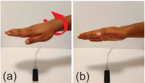
In Axis by Axis mode, the user selects the axis to rotate through a button on the HMI. To enable rotation of the selected axis, the user has to save an initial position. The initial position is saved when the user closes the right hand and is defined as the rotation of the palm around a vector pointing away from the user along the palm, in the fingers direction. When the initial position is saved, the user can start to rotate the palm, see Figure 3. Clockwise rotation of the user’s palm will decrease the axis value and counter clockwise rotation will increase the axis value. The robot simultaneously changes the angle of the selected axis while the user is rotating the palm. If the user changes rotation direction from clockwise to contra-clockwise, the robot starts to change the angle in the opposite direction. When the user wants to stop the rotation of the axis, the user holds the left hand closed above the Leap Motion controller.
Figure 2. The figure describes (a) the suggested height of hands from the Leap Motion controller, (b) saving of initial position, (c) saving of TCP position.
Robot manipulation based on Leap Motion - Work
4.2.7 Collaborative Jog
In Collaborative Jog mode, the Leap Motion controller is mounted close to the tool on the robot. This mode works according to the same principal as the Imitate Jog mode, the TCP of the robot follows the motion of the user’s centre point of the right palm. Because of the placement of the sensor, the users working range with this mode is not limited to the sensors sensing space. When the user moves its palm the robot will follow and consequently also the Leap Motion controller. This jog mode has not been tested due to safety restrictions regarding operation of the robot in automatic mode.
4.2.8 Rotation of the tool
In Rotation of Tool mode, the user can rotate the TCP around the x-axis, y-axis or z-axis according to the current work object. The user selects the Rotation of Tool mode through a button on the HMI. To enable rotation, the user first has to select which axis to rotate. The user selects axis by holding a specific number of fingers above the con-troller, see Figure 4. The axis is specified as follows; x-axis = two fingers, y-axis= three fingers and z-axis=five fingers. When the axis is selected, the user closes the right hand to initiate rotation. To achieve rotation, the user rotates its own palm around a vector pointing away from the user along the palm, in the fingers direction, see Figure 3. Clock-wise rotation of the user’s palm results in positive rotation around the selected axis in relation to the current selected coordinate system. The robot simultaneously changes the angle of the selected axis while the user is rotating the palm. If the user changes rotation direction from clockwise to contra-clockwise, the robot starts to change the angle in the opposite direction. When the user wants to stop the rotation of the axis, the user holds the left hand closed above the Leap Motion controller.
Figure 3. The figure describes how rotation performed in Rotation of Tool and Axis by Axis mode.
4.2.9 Additional options
Except the different options to manipulate the robot that is mentioned above, the HMI contains several other options, which objectives are to increase the user friendliness and especially the usefulness of the method. The scaling option can be used for both Linear Jog, Imitate Jog, Collaborative Jog and Axis by Axis. The option can be used e.g. when the user wants to reach a specific point with the TCP and enables the user to reach the desired position with higher absolute accuracy. The scaling option consists of four dif-ferent scaling factors, where the default value is none scaling. The three other options are Large, Medium and Small. Small stands for the smallest movement of the TCP and Large for the largest but still less than the default value. The Delete Target option makes it possible for the user to delete a saved target. The Save Joint Values option makes it possible to save the joint values obtained by the use of Axis by Axis. This makes it possible for the user to continue to jog the robot by Linear Jog or Imitate Jog with the new axis values obtained after the use of Axis by Axis.
4.3 Program Functionality
This section describes the method from a programmer’s perspective and gives the in-formation necessary in order to understand the program code behind the application and to be able to develop it further.
4.3.1 Modularity
One objective during the development process has been to ensure that the application program has a high level of modularity. There are several reasons to why the program should be modular. A modular program will e.g. ease debugging, code adjustments and readability. In order to achieve this, the program functionalities are divided into inter-changeable modules in two levels. On the highest level, the program utilizes two differ-ent classes, one class which handles everything concerning the Leap Motion controller and one class which correspondingly handles the robot controller. The transfer of data from the Leap Motion class to the robot class is consistently performed through method calls from the Leap Motion class to the Robot class. The Leap Motion class reads the input from the Leap Motion controller and determines which data to send and which method to call through the logic in the program code. All the logic behind
Figure 4. The figure describes how the axis is selected in Rotation of Tool. (a) rotation around x-axis, (b) rotation around y-axis, (c) rotation around z-axis.
Robot manipulation based on Leap Motion - Work
which method to call and when based on user input is found in the Leap Motion class. The robot class contains the connection to the robot controller and enables modifica-tion of the parameters related to it. The different methods are the link between the Leap Motion class and the Robot class and is used to modify the appropriate parameters within the robot class. The explained program structure eases replacement of input de-vice to the system without an extensive restructuring of the code. In a situation, where the end user prefers a different device, e.g. a 3D-mouse instead of a Leap Motion con-troller, the application could be modified through the replacement of existing logic with logic according to the input from the 3D-mouse. With a modular structure of the pro-gram, a modification like this would involve minimal changes in the Robot class and the methods used for transferring commands to it. If the application should be enlarged with new functionality instead, this can be handled by adding new methods to the ex-isting code. On a lower level, the structure of the program is based on the control flow tool, Switch. Both the Leap Motion class and the Robot class includes a switch state-ment where each function of the program is located under a switch section. Which switch section that should be executed is determined through the user input in the HMI where the options in the HMI is connected to methods that modify the value of both switch expression. To increase the readability of the code, the value of the switch ex-pression in the Leap Motion class corresponds to the same value in the Robot class. A program based on switch sections is easy to debug, adjust and sometimes faster than a program based on normal IF statements.
4.4 Program
When starting the application, an object of the Leap Motion class is derived. This im-mediately creates the connection to the Leap Motion controller and activates the track-ing of gestures. Further, the user is prompted to scan the network for controllers. When the scan is completed all the controllers, both real and virtual controllers that are con-nected to the network, are visualized in a list. Selection of the requested controller will establish the connection to that specific controller. In the main menu of the HMI, the user has to press “Start Robot” to enable all program functions. The manipulation of the robot is done through modification of RAPID data. To accomplish this, some amount of RAPID code has to be predefined. As stated in chapter 2.8, the PC SDK do not support direct control of the servo system of the robot. Another approach for ma-nipulation of the robot is, therefore, to utilize the PC SDK together with a predefined RAPID program.
To enable jogging of the robot, the RAPID program have to contain one base robot target. A robot target is of the data type struct. This data type is used to encapsulate small groups of related data. A robot target contains data regarding the position of the TCP, the additional axes and the axis configuration in the move instruction. The posi-tion in x, y, z of the TCP is expressed in mm relative to the work object’s coordinate system used while defining the robot target. Further, the orientation of the tool is spec-ified relative to the same work object and expressed in quaternions (q1, q2, q3, q4). The axis configuration defines the values of the axis and needs to be specified because of the robot’s ability to approach a position in various ways [20]. The base target will al-ways have position data [x, y, z] equivalent to the position data of the TCP. While the robot is set to automatic mode and the application is running, jogging of the robot can be enabled because the data included in the base robot target will be continually updated according to the data sent from the application. This means that when the base target
is updated, the position of the TCP will be updated accordingly. The method, which is called from the Leap Motion class during Linear Jog, updates the position of the base target by continuously adding a control variable with constant value ten to [x, y, z] co-ordinate of the base target depending on the selected jogging direction. In Linear Jog, the position of the TCP is incremented by the value of the control variable. In other words, the TCP will move at a constant speed until the stop method is called. The stop method sets the control variable, which is added to the coordinates of the base target to zero and as a result, the TCP stops at the new position. For Imitate Jog, the approach is different. The method, which is used to update the position of the TCP in Imitate Jog, is sending the values, which the coordinates of the base target shall be equal to. Depending on which option that is selected in the Imitate Jog mode, x-direction, y-direction, z-direction or all three, different parameters in the base target is updated. In order to keep the robot from moving the TCP to [0, 0, 0] when the Imitate Jog mode initiates, before the user starts to send data, the current position of the base target have to be saved and used as the default values for the method. Therefore, the Leap Motion class reads and saves the current position data of the base target as a first step when Imitate Jog is initiated. The second step is to save the initial position of the user’s right hand palm centre point. This in order to enable calculation of the difference between the initial position and a new position of the hand and send this data as a command of how much the robot controller should adjust the position of the base target/TCP. The final argument, which is sent to the robot simultaneously while the user moves the hand, is therefore the initial position of the base target and the difference between the right hand palm centre point and the current right hand palm centre point. The Leap Motion controllers sensing space limit how much the user can move the base target. The initial position of the base target is only adjusted if the user chooses to offset the start position of the hand in order to expand the working range in a specific direction. In this case the user saves a new current position and moves the TCP in relation to that one instead. In this way, it is possible for the user to expand the working range.
In the Rotation of Tool mode, the orientation of the tool is modified while the x, y, z values stays the same. The base target, which as mentioned before, contains data about the orientation of the tool expressed in quaternions (q1, q2, q3, q4). The PC SDK pro-vides a method which, makes it possible to change the orientation by modification of the Euler angles in degrees. By the use of this method it is possible to increase or de-crease the current angle values of a chosen axis in order to rotate the robot around the base target/TCP. The orientation data of the base target is continuously incremented when the user rotates its hand. When the user stops the rotation of the tool, by closing the left hand, no more values will be transferred to the controller and the robot will maintain the tool in the new orientation.
To enable Axis by Axis jog, a base joint target has to be predefined in the RAPID program. A joint target is used to define the position of all six axes and the external axis when the instruction MoveAbsJ (Move Absolute Joint) is used in the rapid code. The position of the axes is given in degrees for rotating axes and mm for linear axes, positive or negative, with respect to the axes calibration position [20]. When the Axis by Axis mode is selected, the RAPID program continuously updates the position data of the base joint target. As mentioned in chapter 2.8, the PC SDK do not contain any method which allows transfer of axis values from a joint target to a robot target. Therefore, to make it possible to change between the Axis by Axis mode and the different jogging modes and still be able to use the new position data obtained from the use of the Axis by Axis mode in the base target, the transfer of data has to be done in the RAPID
Robot manipulation based on Leap Motion - Work
program. The RAPID language provides functions, which transfer data from a robot target to a joint target or the other way around. If the user press “Save joint target values” on the HMI, a method in the application will make an IF condition in the RAPID program true, which saves the base joint targets data into the base robot target. This makes it possible for the user to continue to jog the robot from the position, which the TCP ended up at after the use of the Axis by Axis mode.
To enable the creation of a program, the predefined RAPID program has to contain several robot targets. Again, as stated in chapter 2.8, the PC SDK do not support the creation of robot targets “on the fly”. The limitations, which this implies, can be re-duced with different approaches. One approach, which is used in this method, is to predefine the desired number of robot targets in the RAPID program. When the user performs a saving operation the data contained in the base target is saved in the next predefined robot target. If ten robot targets are predefined in the RAPID code, aside from the base target, the user has the possibility to do a program consisting of ten points. Another approach is to load predefined robot targets from a file.
4.5 User test
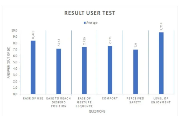
A group of seven students was asked to perform a user test. The aim of the test was to get objective feedback from first time users to enable evaluation of the application in terms of ease to use and intuitiveness. Various factors, including the time to perform the test, were considered. All the students had previous experience of robot program-ming thus the students were first asked to perform the test with the use of the flex pendant. After that, the students were handed a user instruction of the Linear Jog. When the functions of the Linear Jog was clear, the student was given a couple of minutes to get familiar with the functions before performing the test with the presented applica-tion. After the test was completed the student was handed a questionnaire, which can be seen in Appendix 1.A. The questions that were asked was;
• “How easy was the application to use?”
• “How easy was it to reach the desired position?”
• “How easy was it to remember the sequence of gestures?” • “How comfortable were the gestures in terms of hand posture?” • “How safe felt the application?”
• “How much did you enjoy to use the application for manipulation of the robot?” The students were asked to rate each question between one and ten according to the students experience during the user test. The questionnaire also contained two ques-tions were the student could give more general feedback. These quesques-tions were; • “Was anything particularly confusing about the HMI, the used gestures or the
pro-totype in general?”
• “Is there anything you are missing that you would like to see in a final version?”.
4.5.1 Test setup
The test was formed as a pick and place task where a transparent plastic glass should be picked from one specified position and then placed at another specified position. The test person was limited to use the Linear Jog mode because this mode is considered
to be the most stable mode. The task consisted of five points, which had to be defined of the test person. The points were: a Home position, an Approach Pick position, a Pick position, an Approach Place position and a Place position. The tool, which was a vacuum gripper, was already calibrated and the work object was predefined. The test setup can be seen in Figure 5.
While performing the test by the use of the flex pendant, the test person had to create five robot targets and define the move instructions including the position of the robot targets according to the task. The instruction for activate/deactivate the tool also had to be inserted. While performing the test by the use of the presented application, the test person only had to define the robot targets positions. Before the test, a Pick and Place template was created, which contained all the necessary RAPID code includ-ing five robot targets, digital output to activate/deactivate the tool, move instruction, speed data and zone data. The robot targets were inserted in a path, where all the above mentioned were placed in the correct order according to the task.
4.6 Customization of the method
The presented application is possible to customise in order to suit the end user’s specific needs. Due to the limitations of the PC SDK, as mentioned in chapter 2.8 it is not possible to create RAPID data from the application. A lot of predefined RAPID code is required in order to fully make use of the methods functionality. Since this method is developed to suit users without earlier experience in robot programming, the user should preferably not be responsible for the predefinition of code. One way to ap-proach this, is to provide RAPID program templates together with the application which is formed in order to fit the end user’s requirements. The template can be reached from the base module by adding a condition in main, which can be controlled from the application. When the condition is true, the robot will run the template module. One
.
Robot manipulation based on Leap Motion - Work
example of how a template could be formed is the Pick and Place program included in this work and used in the user test. The template is provided as a separate module which only needs to be loaded to the robot controller. Within the template, the robot targets, a joint target and the Pick and Place path with digital output signals are already declared. The Pick and Place template consist of five robot targets, which positions have to be defined according to the specification of the specific Pick and Place task. The user saves positions which are in line with the position of a home position, an approach pick po-sition, a pick popo-sition, an approach place position and a place position. The digital out-put which controls when the tool in this case, a vacuum gripper, is on and off is already defined in the Pick and Place path. Therefore, when the definition of the robot targets is done, the user can press “Run Program” and the robot executes the task.
If the end user wants a template provided together with the application, some mod-ifications in the application code have to be performed in order to access the specific template. Some data used in the methods in the robot class, which enables writing and reading RAPID data, requires unique input arguments which are related to the target module. The arguments that are defined for the application is: which module, robot target, joint target or variable that shall be modified and makes it possible for the user to utilize all functionality of the application within the new template. While forming a new template, a new module, with a unique name e.g. “Module3” should be created. In “Module3” the task specific RAPID code is inserted. The programmer should decide on an action which assigns the string variables with the values corresponding to the new module. This can preferably be done through a button or a list, where a button press results in e.g. string ModuleName = “Module3”.
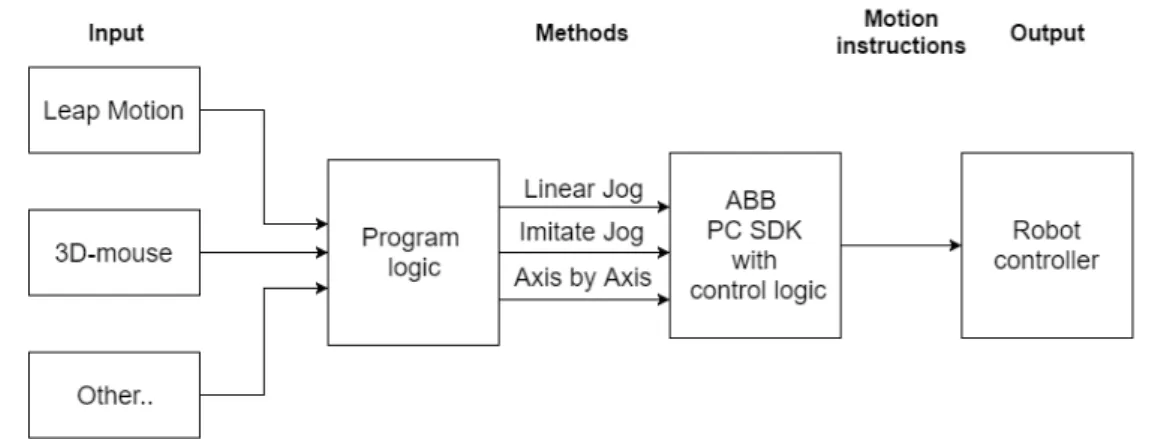
Further, because of the structure of the program code, it is possible to change the device used for input to another external device than a Leap Motion controller which can be seen in Figure 6. This makes it possible for end users to choose the device that best suits their requirements. This will imply extensive program modifications, but as mentioned before in the Program functionality subsection Modularity, the modifica-tions of the code can be isolated to the part of the code that contains the logic related to the external device.