Coupling forces in the B-triple
and truck-B-double
combinations
An extension of the 18868 ISO standard for D-
and V-values and analysis of the normative case
Fo
to: V
alentin A
gachi, Mostpho
tos.com
VTI rapport 1031A Published 2020 vti.se/publications Bruno Augusto Fredrik Bruzelius Sogol Kharrazi Bolennarth Svensson
VTI rapport 1031A
Coupling forces in the B-triple and
truck-B-double combinations
An extension of the 18868 ISO standard for D- and
V-values and analysis of the normative case
Bruno Augusto
Fredrik Bruzelius
Sogol Kharrazi
Bolennarth Svensson
Author: Bruno Augusto (VTI), Fredrik Bruzelius (VTI), Sogol Kharrazi (VTI), Bolennarth Svensson (EMA-QC)
Reg. No., VTI: 2019/0186-8.2 Publication No.: VTI rapport 1031A Published by VTI, 2020
VTI rapport 1031A
Abstract
The forces in the couplings of articulated vehicle combinations, propel and fully determine the path of any towed unit thus playing a significant role in the vehicle behavior. A failure in the coupling could potentially have a devastating effect if it occurs while driving in traffic. To prevent this from
happening, states and road authorities impose requirements in terms of tolerated forces on any coupling selection.
The current legal requirement framework is based on an ISO standard, that stipulates minimum force levels that the couplings should stand. These forces have been derived under semi-empirical
assumptions for a set of five vehicle combinations.
The present report aims to extend the coupling requirements to two vehicle combinations that are candidates to become legal on the public road network. Due to the semi-empirical nature of the ISO standard, validation needed to be performed. The here presented requirements for the two new combinations were validated against simulation models and checked for reasonable requirements for some example weights of the combinations.
The proposed requirements are aligned with the existing requirements derived from the ISO standard. This implies that they could be used to form the legal requirements on these vehicle combinations. However, further investigations on well-grounded deduced requirements should be performed to secure safety margins.
Title: Coupling forces in the B-triple and truck-B-double combinations.
An extension of the 18868 ISO standard for D- and V-values and analysis of the normative case.
Author: Bruno Augusto (VTI)
Fredrik Bruzelius (VTI) Sogol Kharrazi (VTI)
Bolennarth Svensson (EMA-QC)
Publisher: Swedish National Road and Transport Research Institute (VTI)
www.vti.se
Publication No.: VTI rapport 1031A
Published: 2020
Reg. No., VTI: 2019/0186-8.2
ISSN: 0347–6030
Project: TS-Kopplingskrafter
Commissioned by: Swedish Transport Agency
Keywords: Long vehicle combinations, Coupling forces
Language: English
VTI rapport 1031A
Referat
Kopplingskrafterna hos fordonskombinationer är de krafter som helt styr vart efterföljande fordon tar vägen. Ett brott på en sådan koppling kan därför få förödande konsekvenser om det inträffar i trafik. För att minska risken för sådana händelser, ställer myndigheter krav på bärighet hos dessa kopplingar. Det nuvarande rättsliga kravet är baserat på en ISO-standard som anger de minsta kraftnivåer som kopplingarna ska tåla. Dessa krafter har härletts utifrån semi-empiriska antaganden och explicita uttryck finns angivna för fem olika fordonskombinationer.
Denna rapport syftar till att utöka kravet på kopplingskrafterna för två nya fordonskombinationer som i en framtid kan bli lagliga på det allmänna vägnätet. På grund av uttrycken i ISO-standardens semi-empiriska natur, måste validering utföras. En jämförande simulering av kopplingskrafterna för de två nya samt de i ISO standarden existerande utgör en del i valideringen. En rimlighetskontroll av resultatet av uttrycken med existerande kopplingar på marknaden utgör den andra delen av valideringen.
Valideringen visar att uttrycken ger rimliga krav som är i linje med vad ISO-standarden ger för existerande fordonskombinationer. Detta innebär att de kan användas som grund för framtida lagkrav för dessa fordonskombinationer. Ytterligare undersökningar av välgrundade, deducerade krav bör dock utföras för att säkerställa säkerhetsmarginaler och reducera empirin.
Titel: Kopplingskrafter för B-trippel och Lastbil-B-dubbel-kombinationerna.
En utökning av 18868 ISO standard för D- och V-värden och analys av det normativa fallet.
Författare: Bruno Augusto (VTI)
Fredrik Bruzelius (VTI) Sogol Kharrazi (VTI)
Bolennarth Svensson (EMA-QC)
Utgivare: VTI, Statens väg- och transportforskningsinstitut
www.vti.se
Serie och nr: VTI rapport 1031A
Utgivningsår: 2020
VTI:s diarienr: 2019/0186-8.2
ISSN: 0347–6030
Projektnamn: TS-Kopplingskrafter
Uppdragsgivare: Transportstyrelsen
Nyckelord: Långa fordonskombinationer, kopplingskrafter
Språk: Engelska
VTI rapport 1031A
Preface
This report is the result of a project initiated by Omar Bagdadi at the Swedish Transport Agency. The primary goal of this project was to extend the existing ISO standard for computing normative coupling forces for two specific vehicle combinations: B-triple and Truck-B-double. The project was funded completely by the Swedish Transport Agency and the simulations, derivations and analysis were done by the three authors at VTI, while Bolennarth Svenson of EMA-QC, previously with the VBG, discussed results and advised on directions.
Göteborg, February 2020
Fredrik Bruzelius Project leader
VTI rapport 1031A
Quality review
Internal peer review was performed on 14 February 2020 by Mattias Hjort. Fredrik Bruzelius has made alterations to the final manuscript of the report. The research director Arne Nåbo examined and approved the report for publication on 3 March 2020. The conclusions and recommendations
expressed are the authors’ and do not necessarily reflect VTI’s opinion as an authority.
Kvalitetsgranskning
Intern peer review har genomförts 14 februari 2020 av Mattias Hjort. Fredrik Bruzelius har genomfört justeringar av slutligt rapportmanus. Forskningschef Arne Nåbo har därefter granskat och godkänt publikationen för publicering 3 mars 2020. De slutsatser och rekommendationer som uttrycks är författarnas egna och speglar inte nödvändigtvis myndigheten VTI:s uppfattning.
VTI rapport 1031A
Table of Contents
Summary ...9 Sammanfattning ...11 1. Introduction ...13 2. Background ...153. ISO 18868:2013 – Coupling strength requirements ...16
4. Extension of the ISO requirements ...17
4.1. The considered vehicle combinations ...17
4.2. D- and V- values for the new vehicle combinations ...18
4.3. Converting to field measurable quantities ...19
4.3.1. Estimating Ub ...20
4.4. Example calculations for the 74-ton case ...21
5. Alignment with current metrics ...22
5.1. Test case for comparison ...22
5.2. The simulated vehicles ...22
5.3. D values comparison ...23
5.3.2. Tractor led combinations ...24
5.3.3. Remarks ...24
5.4. V-value comparison ...25
6. Discussion ...26
7. Concluding remarks ...29
VTI rapport 1031A 9
Summary
Coupling forces in the B-triple and truck-B-double combinations. An extension of the 18868 ISO standard for D- and V-values and analysis of the normative case
by Bruno Augusto (VTI), Fredrik Bruzelius (VTI), Sogol Kharrazi (VTI) and Bolennarth Svensson (EMA-QC)
The forces in the couplings of articulated vehicle combinations, propel and fully determine the path of any towed unit thus playing a significant role in the vehicle behavior. A failure in the coupling could potentially have a devastating effect if it occurs while driving in traffic. To prevent this from
happening, states and road authorities impose requirements in terms of tolerated forces on any coupling selection.
Requirements for the coupling arrangements are stated in terms of maximum forces in the directions more susceptible to failure. For fifth wheel arrangements, this implies the longitudinal direction, while in the case of a clevis coupling on a drawbar, requirements are stated in both longitudinal as well as vertical directions.
There is a general drive to allow longer and heavier vehicle combinations on the road network today. The main drive behind this is transport efficiency. In this report, two vehicle combinations that potentially could be made legal is investigated concerning their coupling requirements. The combinations are,
• Tractor + link trailer + link trailer + semi-trailer • Truck + converter dolly + link trailer + semi-trailer
The first one is often referred to as a B-triple combination, while the second one does not have an established name. Hence, a combination of established terms was used for this vehicle combination herein referred to as a truck-B-double.
The coupling requirements for existing combinations are based on an ISO standard for these combinations. The objective of the project was to extend the ISO to the two above mentioned combinations. The standard is based on a take-off scenario, where the coupling forces are computed based on the masses of the wheel groups and the loads on the kingpin of the fifth wheels. The expressions have been derived partly through mechanical arguments and partly empirical through measurements.
Expressions were derived using similar arguments that the standard once was derived under for the B-triple and truck-B-double combinations. However, due to the semi-empirical nature of the expressions, other means for validation was required. The first simple step was to investigate if the expressions resulted in reasonable requirements for a configuration that is a candidate to become legal. Another validation was made against a complex simulation model. A relative comparison was made using the existing combinations and their corresponding ISO expressions. Both validations suggest that the proposed expressions are reasonable and could be suggested to be included in coming legislations.
The empirical nature of the existing ISO expressions and the once proposed in this report suggest that there is a risk with that the safety margins are not fully understood. Future extensions could, therefore, be based on a new framework with scenarios and expressions better grounded in the laws of physics. Simulations in this report suggest that these should be different depending on the type of coupling.
VTI rapport 1031A 11
Sammanfattning
Kopplingskrafter för B-trippel och Lastbil-B-dubbel-kombinationerna. En utökning av 18868 ISO standard för D och V-värden och analys av det normativa fallet
av Bruno Augusto (VTI), Fredrik Bruzelius (VTI), Sogol Kharrazi (VTI) och Bolennarth Svensson, (EMA-QC)
Kopplingskrafterna hos fordonskombinationer är de krafter som helt styr vart efterföljande fordon tar vägen. Ett brott på en sådan koppling kan därför få förödande konsekvenser om det inträffar i trafik. För att minska risken för sådana händelser ställer myndigheter krav på bärighet hos dessa kopplingar. Kraven för kopplingsanordningarna anges i termer av maximala krafter i riktningarna som är
mottagliga för brott och utmattning. För kopplingsarrangemang med ett femte hjul innebär detta ett krav primärt i längsgående riktning, medan kraven anges i både längsgående och vertikala riktningar när det gäller en ögle-koppling på en dragstång.
En trend i Europa idag är att tillåta längre och tyngre fordonskombinationer på vägarna. Den främsta drivkraften bakom denna trend är transporteffektivitet. I denna rapport undersöks två längre
fordonskombinationer med avseende på deras krav på kopplingskrafter. Dessa kombinationer, som potentiellt kan komma att tillåtas i vägnätet, är
• Dragbil + link + link + påhängsvagn • Lastbil + dolly + link + påhängsvagn
Den första benämns ofta i litteraturen som en B-trippelkombination, medan den andra inte har ett etablerat namn. Denna rapport kommer att benämna denna kombination Lastbil-B-dubbel, som utnyttjar en etablerad benämning för den bakre delen av kombinationen.
De lagstadgade kopplingskraven för befintliga fordonskombinationer är baserade på en ISO-standard. Syftet med detta projekt var att utvidga de uttryck som finns i ISO till de två ovan nämnda kombina-tionerna. Standarden är baserad på en tänkt startsituation, där kopplingskrafterna beräknas baserat på massorna på hjulgrupperna och belastningarna på kingpin på femte hjulen. Dessa uttryck har
utvecklats dels genom fysikaliska argument, dels genom empiri och mätningar.
Med liknande argument som för ISO uttrycken, har uttryck för kombinationerna av B-trippel och lastbil-B-dubbel utvecklats här. På grund av ISO uttryckens semi-empiriska natur krävs emellertid också en validering av de nya uttrycken. Det ena delen av valideringen bestod i att undersöka om uttrycket resulterade i rimliga värden och om det resulterar i kopplingar som existerar på marknaden. Den andra delen av valideringen gjordes med hjälp av simulering av matematiska modeller. En relativ jämförelse av resultatet från de befintliga kombinationerna och deras motsvarande ISO-uttryck med de nya kombinationernas uttryck och simuleringsresultat genomfördes. Båda valideringarna tyder på att de föreslagna uttrycka är rimliga och att de skulle kunna ingå i en kommande lagstiftning.
Den empiriska karaktären hos de befintliga ISO-uttrycken och de här föreslagna, antyder att det finns en risk med att säkerhetsmarginalerna inte är helt intuitiva. Framtida uttryck och regelverk bör därför baseras på ett ramverk där situationer och uttryck bättre grundas i fysikens lagar. Simuleringar i denna rapport indikerar att både situationer och uttryck bör vara olika beroende på typen av koppling och kombination.
VTI rapport 1031A 13
1.
Introduction
The forces in the couplings of articulated vehicle combinations, propel and fully determine the path of any towed unit thus playing a significant role in the vehicle behavior. A failure in the coupling could potentially have a devastating effect if it occurs while driving in traffic. To prevent this from
happening, states and road authorities impose requirements in terms of tolerated forces on any coupling selection.
Requirements for the coupling arrangements are stated in terms of maximum forces in the directions more susceptible to failure. For fifth wheel arrangements, this implies the longitudinal direction, while in the case of a clevis coupling on a drawbar attached to a center axle trailer, requirements are stated in both longitudinal as well as vertical directions.
Testing a coupling for compliance with specifications is achieved by exposing it to repeated
(sinusoidal) forces in a test rig, with an amplitude described by the rating of the coupling. This makes the requirement a mixture between safety margins and fatigue. Further details can be found in ISO 8718:2001, in the reference list at the end of the report as well as in the regulation UNECE R55. Specifying the amplitude of the rating forces at the couplings is the challenge that this report is concerned with.
The coupling ratings should comfortably cover expectable driving conditions, while not being oversized, thus minimizing extra weight as well as usage of material and resources. Hence,
determining a rating that is “just right” depends on the use case for the coupling. The problem at hand lies in finding an appropriate dimensioning case representing driving situations that would lead to high force amplitudes at the coupling. This dimensioning case should be connected to the real usage of the vehicle, but still, also give enough margin for potential unknown situations and loads.
Once a dimensioning case is defined, determining the force levels at the joints is far from trivial. Field tests are too expensive and usually complicated to perform. References to such measurements are scarce in the literature related to coupling forces, see (Svensson et. al. (2016)) and (Sweatman (1980)). In the absence of such measurements, expressions to derive coupling forces and their respective ratings, are a necessity.
Just like in the dimensioning case, a balance needs to be struck between complexity and simplicity of expressions to compute maximum force amplitude at a joint. From a practical perspective, such expressions need to be simple and understandable and depend on quantities that can be readily measured, estimated, or available from a supplier. From an accuracy point of view, the expressions need to be complex enough to incorporate the main phenomena that contribute to the maximum force. This balance is non-trivial and may sometimes be governed by non-factual opinions rather than well-grounded evidence.
Existing expressions have been developed primarily by Sweatman, in Australia, in the eighties, see (Sweatman (1980)) and (Sweatman (1987)). In this work, the dimensioning case is given by starting form standstill situation. The driving torque of the propelled lead vehicle in a vehicle combination is generating a propelling force that is propagated throughout the combination via the couplings. Sweatman derives equations for a steady-state as well as for dynamic situations and compares these with field measurements. Finally, he derives simplified equations based on measurements and analytical expressions. These simplified equations are the basis for the existing ISO standard (ISO 18868:2013) that in turn is the source for the Swedish regulations.
The ISO equations are derived for five different vehicle combinations. This report aims to extend this set of equations to new vehicle combinations, not currently covered, that will potentially become legal on the Swedish road network: The B-tipple (Tractor + Link Trailer + Link Trailer + Semi-Trailer) and the Truck-B-double (Rigid truck + converter dolly + Link Trailer + Semi-Trailer) combinations. Allowing longer and heavier combinations on the road network is part of a larger strategy in Sweden
14 VTI rapport 1031A (and many other countries) to increase transport efficiency, see for example the work in the
Performance Based Standards project, (Kharrazi et. al. (2017)).
Due to the semi-empirical nature of the expressions used in the ISO standard today, this work takes on a semi-empirical way of deriving the new equations. Expressions for rating forces of two new
combinations are derived, keeping closely with the reasoning behind the existing ISO expressions. The validity of these expressions is then checked by way of simulations. Comparisons between simulations of ISO covered vehicle combinations and the two new vehicle combinations will be the metric used to legitimize the new expressions. Finally, the expressions are further scrutinized by assessing their outcomes when applied to the heaviest (74 ton) vehicle combination currently allowed in Swedish roads.
Additionally, this work also discusses the potential risks with the given strategy of the ISO standard and some suggestions on how this could be improved concerning both expressions and the
VTI rapport 1031A 15
2.
Background
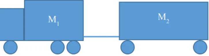
The so-called D-value see e.g. ISO 18868:2013, is a rating to specify a maximum longitudinal force that a coupling in a vehicle combination should withstand. This D-value is historically computed according to a simple assumption between two vehicles under the case that the propelling lead vehicle is accelerating. Consider the truck and trailer below.
Figure 1 A simple truck-trailer combination
For a steady-state acceleration 𝑎𝑎𝑋𝑋 the force acting on the combination is,
𝐹𝐹𝑥𝑥 = 𝑎𝑎𝑥𝑥(𝑀𝑀1+ 𝑀𝑀2) 1
The corresponding force on the connection is consequently given by, 𝐹𝐹𝐷𝐷= 𝑎𝑎𝑥𝑥𝑀𝑀2=𝑀𝑀𝐹𝐹𝑥𝑥𝑀𝑀2
1+ 𝑀𝑀2 2
Assume that a force can be generated by the truck that would lead to an acceleration of 1 g for the truck without the trailer connected,
𝐹𝐹𝑥𝑥= 𝑀𝑀1𝑔𝑔 3
Such a force would require all wheels of the truck to be driven, together with a friction coefficient between the road and the tyres equal to one, and would give the following coupling force,
𝐹𝐹𝐷𝐷=𝑀𝑀𝑀𝑀1𝑀𝑀2
1+ 𝑀𝑀2𝑔𝑔 4
It should be noticed that expression 4 is symmetric and the same result (except for a minus sign) can be derived by assuming the second unit to brake. It is here presented for the acceleration case to align with the ISO standards that this report aims to extend. The braking case could however be a relevant case for future updates.
Equation 4 is, of course, an overestimate of the steady-state forces that arise in a real situation, due to the assumption of force generation in equation 3. Besides, there will be transient forces when the acceleration is changed. The dynamic forces are mainly due to the compliance of the couplings (and their mountings etc.) and due to the pitch motion of the involved vehicles. In Sweatman (March 1980) such expressions are derived considering mainly the compliance using a combination of analytical relations and empirical ones. This is further developed and fitted to the expressions found in the ISO 18868:2013 in Sweatman (1987).
M1 M2
16 VTI rapport 1031A
3.
ISO 18868:2013 – Coupling strength requirements
ISO 18868 was released in 2013 under the title Commercial road vehicles – Coupling equipment
between vehicles in multiple vehicle combinations – Strength requirements. This standard provides
dimensioning guidelines for the couplings of long combinations of vehicles, focusing on two coupling types, 5th wheel and drawbar.
The forces generated in the coupling between two vehicles are dependent on the coupling type, the mass of the vehicles and the external forces the vehicles are subjected to. This makes it impossible to dimension the couplings independently of their use cases, implying that the dimensioning
requirements are computed on a use case basis; a use case being herein represented as a vehicle combination.
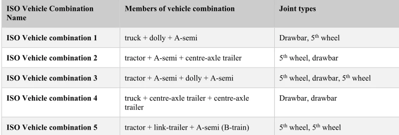
Taking this use case approach, ISO 18868:2013 provides strength requirements for the joints in five different vehicle combinations.
Table 1 - ISO18868:2013 Covered Vehicle Combinations
ISO Vehicle Combination
Name Members of vehicle combination Joint types
ISO Vehicle combination 1 truck + dolly + A-semi Drawbar, 5th wheel
ISO Vehicle combination 2 tractor + A-semi + centre-axle trailer 5th wheel, drawbar
ISO Vehicle combination 3 tractor + A-semi + dolly + A-semi 5th wheel, drawbar, 5th wheel
ISO Vehicle combination 4 truck + centre-axle trailer + centre-axle
trailer Drawbar, drawbar
ISO Vehicle combination 5 tractor + link-trailer + A-semi (B-train) 5th wheel, 5th wheel
The strength requirements given by ISO18868:2013 cover longitudinal forces on the joint, D values, as well as vertical forces on the joint, V values. Both V and D values are computed using a
combination of empiric observations and simple expressions which govern the vehicle dynamics. For the D value, the requirements revolve around equation 4 with modifications to account for load transfer in dynamic situations, as well as modification to mitigate equation’s 4 conservative nature. These modifications are derived from experiments in the field.
VTI rapport 1031A 17
4.
Extension of the ISO requirements
The strength requirement on a given coupling is a function of the load case. Hence, vehicle
combinations which are not covered by the existing standard are lacking an important metric when it comes to evaluation of roadworthiness.
This chapter contains suggestions on how to expand the standard requirements for two vehicles which are currently not covered by ISO18868:2013 but are deemed of relevance for the Swedish
transportation system.
4.1. The considered vehicle combinations
The two vehicle combinations under consideration are the so-called B-triple and Truck-B-double. The B-triple consists of a tractor pulling a link trailer, followed by another link trailer and finally a semi-trailer. In this vehicle combination are all three couplings are made with a fifth wheel. These are attached to the tractor and the two proceeding link trailers. A schematic picture of the vehicle combination is given in Figure 2Figure 2
T
UT U1b U2b
R1b R2b R3b
Figure 2 A B-triple combination consisting of a tractor (TR6x4) with a fifth wheel connection to two link trailers (LT3) and finally a semi-trailer in the end (ST3). This combination is also referred to as TR6x4_LT3_LT3_ST3 in the plots and tables.
The masses of the individual elements of the vehicle combination is not indicated in the figure. Instead, the axle weights (gross weights) are used since they are easy to measure. Formally, these are forces, but in the nomenclature used here, they are the corresponding masses that would result in these forces. Besides the gross weight of the tractor (T), the gross axle loads on the trailer (R1b and R2b), the
load from the trailers to the fifth the wheel (UT, U1b , and U2b) are also marked in the figure. These
quantities are used in the next section in the expressions for the strength requirements.
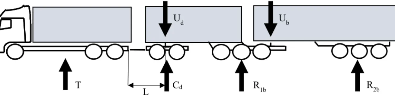
T Cd
Ud Ub
R1b R2b
L
Figure 3 A Truck B-double combination. The figures also referred to as TK6x4_DY2_LT3_ST3.
18 VTI rapport 1031A The Truck-B-double combination consists of a rigid truck, a converter dolly, a link trailer and finally a semi-trailer. The combination name Truck-B-double is not established elsewhere and is a mix of terms to describe the involved vehicles. The three couplings are the fifth wheel on the dolly, a fifth wheel in the link trailer, and a drawbar (without a hinge) connected to a clevis coupling connecting the truck to the dolly. These are depicted in Figure 3. The figure also depicts the loads on the axle groups. Also, the length of the dolly converter (L) is given and is measured as the distance between the coupling eye and the coupling point on the fifth wheel of the converter dolly.
4.2. D- and V- values for the new vehicle combinations
Here we will derive expressions for the two vehicle combinations given in the previous subsection. The derivation is made in alignment with how the ISO standard has been derived, and the expressions are stated using similar notation to the one that can be found in the ISO specifications. The basis for the longitudinal forces is the expression 4, but with the interpretation that A represents the load in front of the coupling and B the load after it.
For the B-triple combination, there is only one type of couplings, the fifth wheel. As a first observation, the front most coupling will take the highest load when the tractor starts to propel the vehicle combination. To keep things simple, we let the first coupling be the one that sets the requirement for all couplings in the combination. In the ISO standard, this in accordance with the assumption made for the B-train combination (combination number 5). Hence, only one expression is given for the B-Triple combination.
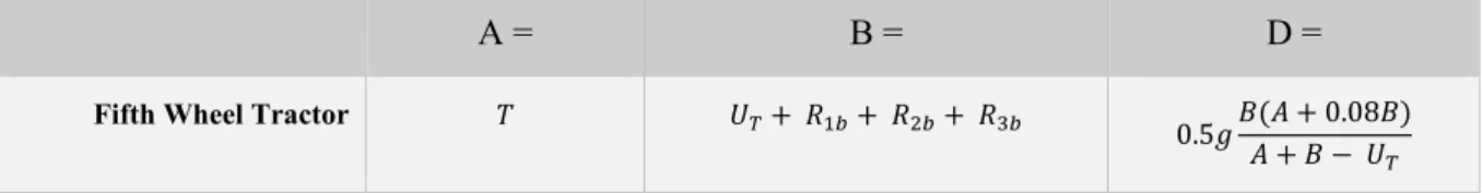
The first fifth wheel in the combination is exposed to the mass of the tractor, denoted T in Figure 2 and A in Table 2 and the sum of the masses of the three trailers, denoted B in Table 2. To derive the D value, we start with equation 4 and the two masses that the coupling is exposed to. Then equation 4 is subjected to three adjustments, in line with the modifications introduced by the ISO standard.
The first adjustment relates to the fact that the total mass is not A+B, as the load on the coupling UT is
counted twice. This is compensated for by subtracting the coupling load in the denominator of equation 4. However, this is only done for the denominator and not the nominator.
Finally, a second and third adjustment is made from empirical data, see Sweatman (1987) to the equation 4 by introducing a scaling factor of 0.5 and a factor of 0.08 of the B coefficient into the A coefficient. These adjustments are made to include dynamic effects. The final expression for the D value is given in Table 2. The expression for D is identical with the existing ISO standard for the B-double combination with the except for one additional trailer.
Table 2 Equivalent ISO18868:2013 D values for B-triple (TR6x4_LT3_LT3_ST3).
A = B = D =
Fifth Wheel Tractor 𝑇𝑇 𝑈𝑈𝑇𝑇+ 𝑅𝑅1𝑏𝑏+ 𝑅𝑅2𝑏𝑏+ 𝑅𝑅3𝑏𝑏 0.5𝑔𝑔𝐵𝐵(𝐴𝐴 + 0.08𝐵𝐵)
𝐴𝐴 + 𝐵𝐵 − 𝑈𝑈𝑇𝑇
For the truck-B-double, we start with the drawbar of the converter dolly. We notice that this is the only coupling that has a vertical force that needs to be rated, due to the rigid mounting of the drawbar to the dolly. The fifth wheel vertical forces are considered in the legislation, but we assume that there is no need to change the existing ones. In the ISO standard, the expression for the drawbar vertical force is independent of the weight of the vehicle in front of the coupling. The vertical force is only dependent on the length of the drawbar and the dolly, i.e. from the eye of the drawbar to the center between the wheels of the dolly, and the load that the dolly is exposed to. Hence, we can again reuse the expression from the ISO standard for the vertical force requirement for the drawbar coupling in this combination.
VTI rapport 1031A 19 In the ISO standard, the longitudinal force on the drawbar is given by equation 4 with an empirical factor of 0.9. We reuse this expression and press the masses before and after the coupling.
For the fifth wheel of the dolly, the longitudinal forces are computed as for the fifth wheels of the B-triple above, but with the exception that the extra compensation is given in the load in front of the fifth wheel rather than from behind. This to compensate for the relatively light weight of the dolly
converter. The final fifth wheel of the link is given by an expression identical to the expression for the B-triple above with the appropriate masses.
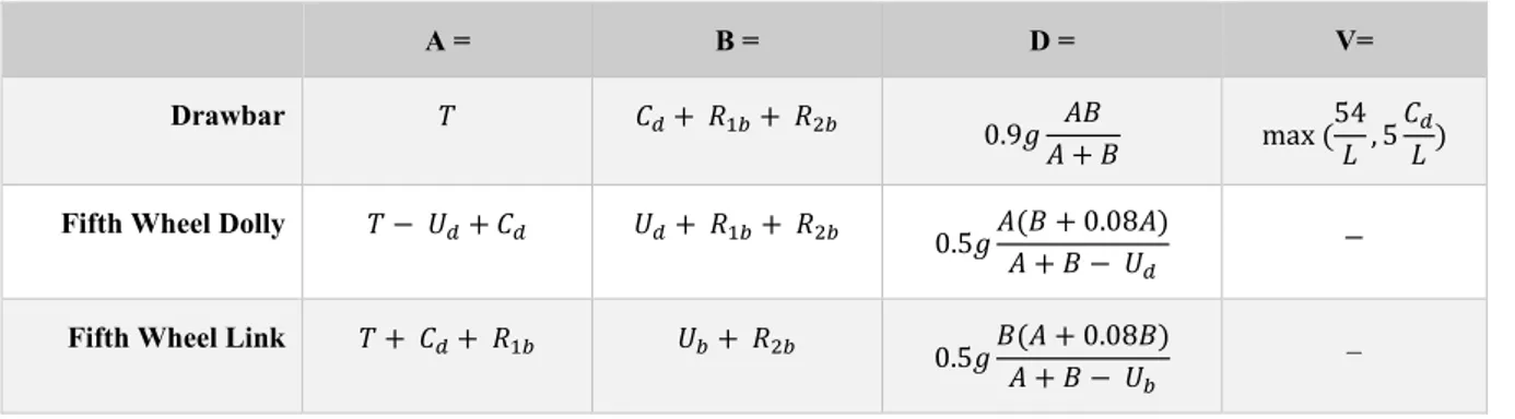
Table 3 Equivalent ISO18868:2013 D and V values for truck B-double combination (TK6x4_DY2_LT3_ST3). A = B = D = V= Drawbar 𝑇𝑇 𝐶𝐶𝑑𝑑+ 𝑅𝑅1𝑏𝑏+ 𝑅𝑅2𝑏𝑏 0.9𝑔𝑔 𝐴𝐴𝐵𝐵 𝐴𝐴 + 𝐵𝐵 max ( 54 𝐿𝐿 , 5 𝐶𝐶𝑑𝑑 𝐿𝐿 ) Fifth Wheel Dolly 𝑇𝑇 − 𝑈𝑈𝑑𝑑+ 𝐶𝐶𝑑𝑑 𝑈𝑈𝑑𝑑+ 𝑅𝑅1𝑏𝑏+ 𝑅𝑅2𝑏𝑏 0.5𝑔𝑔𝐴𝐴(𝐵𝐵 + 0.08𝐴𝐴)
𝐴𝐴 + 𝐵𝐵 − 𝑈𝑈𝑑𝑑
_ Fifth Wheel Link 𝑇𝑇 + 𝐶𝐶𝑑𝑑+ 𝑅𝑅1𝑏𝑏 𝑈𝑈𝑏𝑏+ 𝑅𝑅2𝑏𝑏 0.5𝑔𝑔𝐵𝐵(𝐴𝐴 + 0.08𝐵𝐵)
𝐴𝐴 + 𝐵𝐵 − 𝑈𝑈𝑏𝑏
_
4.3. Converting to field measurable quantities
In this section we will try to make the expressions dependent on quantities that are easy to obtain for example a police officer in a roadside check of the combination. The equations in Table 2 and Table 3 depend on the loads as they are defined in Figure 2 and Figure 3. These definitions are the same as the ones given in the ISO standard and depend on the fifth wheel loads imposed by the vehicle connected to the fifth wheel, the U variables. These loads may not be known and easy to measure. Values that are easy to assess or measure are the axle weights (gross weights) through portable or fixed scales and curb/tare weight of the vehicles from the vehicle suppliers or the road authority’s registry. For the B-triple combination, we readily see that,
𝑈𝑈𝑇𝑇 = 𝑇𝑇 − 𝑊𝑊𝑇𝑇 5
where WT is the curb weight of the tractor. Hence, a slightly modified set of equations can be derived
with dependency only on these variables, see table below.
Table 4 The ISO equivalent for the B-triple given field measurable quantities
A = B = D =
Fifth Wheel Tractor 𝑇𝑇 𝑇𝑇 − 𝑊𝑊𝑇𝑇+ 𝑅𝑅1𝑏𝑏+ 𝑅𝑅2𝑏𝑏+ 𝑅𝑅3𝑏𝑏 0.5𝑔𝑔 𝐵𝐵(𝐴𝐴 + 0.08𝐵𝐵)
𝐴𝐴 + 𝐵𝐵 − 𝑇𝑇 + 𝑊𝑊𝑇𝑇
Modifying the equations for the Truck-B-double combination is more complex as there is a
dependency of quantities that are not readily available. This is since the load distribution is not known from the axle loads and the tare weight of units that also have a load due to cargo. Starting with the converter dolly, the load it is subjected to can be calculated as the difference between the axle load and the tare weight (Wd) of the converter dolly as,
𝑈𝑈𝑑𝑑= 𝐶𝐶𝑑𝑑− 𝑊𝑊𝑑𝑑 6
20 VTI rapport 1031A
𝑈𝑈𝑑𝑑+ 𝑅𝑅1𝑏𝑏 = 𝑊𝑊𝐿𝐿𝑇𝑇+ 𝑈𝑈𝑏𝑏+ 𝑊𝑊𝐿𝐿1 7
where WLT is the tare weight (unloaded weight in Newtons) of the link trailer and WL1 is the weight of
its cargo (in Newtons). Rearranging equation 7 and substituting Ud with equation 6, leads to
𝑈𝑈𝑏𝑏 = 𝐶𝐶𝑑𝑑− 𝑊𝑊𝑑𝑑+ 𝑅𝑅1𝑏𝑏− 𝑊𝑊𝐿𝐿𝑇𝑇− 𝑊𝑊𝐿𝐿1 8
Equation 8 implies that the weight of the cargo on the linked trailer must be known to calculate Ub. If
a force balance is performed to the semi-trailer, in a similar fashion as in equation 7, we get,
𝑈𝑈𝑏𝑏+ 𝑅𝑅2𝑏𝑏= 𝑊𝑊𝑆𝑆𝑇𝑇+ 𝑊𝑊𝐿𝐿2 9
where WST is the tare weight (unloaded weight in Newtons) of the semi-trailer and WL2 is the weight of
its cargo (in Newtons). Equation 9 is dependent on the weight of the cargo on the semi-trailer, a quantity that is not readily available in normal circumstances.
The weight of the cargo is essential to calculate Ub with equations 7 or 9. Measuring said weight can
be done by decoupling each unit, measuring the weights on each axle and stands, and then comparing the measurements with the unit’s tare weight, where the difference between tare weight and the total weight is the cargo weight. However, it is not likely that this can be done in the field thus equations 7 and 9 are not practical, if not impossible, to use in real-world scenarios.
4.3.1. Estimating U
bEven though Ub may not be possible to compute without access to the semi-trailers or linked-trailers
cargo weight, an estimation of this value can be performed, given some assumptions.
The ratio of cargo weight between the last two last trailers of the combination can be expressed as,
𝑊𝑊𝐿𝐿1= 𝑘𝑘𝑊𝑊𝐿𝐿2 10
Solving equations 7,9 and 10 for Ub, and eliminating WL1 and WL2 we get,
1
𝑈𝑈𝑏𝑏 =𝑘𝑘+ 1(−𝑘𝑘(𝑅𝑅2𝑏𝑏− 𝑊𝑊𝑆𝑆𝑇𝑇) − 𝑊𝑊𝐿𝐿𝑇𝑇− 𝑊𝑊𝑑𝑑+ 𝐶𝐶 +𝑑𝑑 𝑅𝑅1𝑏𝑏) 11
Equation 11 shows that, if the relationship between the cargo weight on the two trailers would be known, Ub could be calculated.
It is not reasonable to assume that k is generally known. However, k can be estimated if we assume that the ratio between the trailer’s cargo weight is equal to the ratio between the trailers’ length of the cargo space,
𝑊𝑊𝐿𝐿1= 𝑘𝑘 =𝐿𝐿𝐿𝐿𝑇𝑇 12
𝑊𝑊𝐿𝐿2 𝐿𝐿𝑆𝑆𝑇𝑇
where LST and LLT are the length of the cargo space for the semi-trailer and link trailer, respectively.
These quantities are available in the Swedish vehicle registry, Fordonsregistret, which means Ub could
be estimated in the field. It should be stressed that the assumption in equation 12 may result in inaccurate estimations on Ub if the cargo is disproportionally distributed.
We can now formulate the corresponding table for the Truck-B-double combinations D-values using the equations above as follows.
VTI rapport 1031A 21
Table 5 The ISO equivalent for the Truck B-double combination with field measurable quantities where k is the ratio between the cargo space length of the link and semi-trailers
A = B = Ub= D = Drawbar 𝑇𝑇 𝐶𝐶𝑑𝑑+ 𝑅𝑅1𝑏𝑏+ 𝑅𝑅2𝑏𝑏 _ 0.9𝑔𝑔 𝐴𝐴𝐵𝐵 𝐴𝐴 + 𝐵𝐵 5th Wheel Dolly 𝑇𝑇 + 𝑊𝑊𝑑𝑑 𝐶𝐶+ 𝑅𝑅𝑑𝑑− 𝑊𝑊2𝑏𝑏 𝑑𝑑+ 𝑅𝑅1𝑏𝑏 _ 0.5𝑔𝑔𝐴𝐴 + 𝐵𝐵 − 𝐶𝐶𝐴𝐴(𝐵𝐵 + 0.08𝐴𝐴) 𝑑𝑑+ 𝑊𝑊𝑑𝑑 5th Wheel Link 𝑇𝑇 + 𝐶𝐶+ 𝑅𝑅1𝑏𝑏𝑑𝑑 𝑈𝑈𝑏𝑏+ 𝑅𝑅2𝑏𝑏 1 𝑘𝑘 + 1 (𝑘𝑘(𝑊𝑊𝑆𝑆𝑇𝑇− 𝑅𝑅2𝑏𝑏) − 𝑊𝑊𝐿𝐿𝑇𝑇− 𝑊𝑊𝑑𝑑 + 𝐶𝐶𝑑𝑑+ 𝑅𝑅1𝑏𝑏 ) 0.5𝑔𝑔𝐵𝐵(𝐴𝐴 + 0.08𝐵𝐵)𝐴𝐴 + 𝐵𝐵 − 𝑈𝑈 𝑏𝑏
4.4. Example calculations for the 74-ton case
The current limit of the gross combination mass (GMC) is today 74 tons. For the proposed expressions for the truck b-double combination in previous chapter a total weight of 74 tones would imply D and V values according to,
D-Value V-Value
Drawbar 130kN 30kN
5th wheel dolly 100kN -
5th wheel link 110kN -
For the B-triple combination the corresponding values for a 74-ton combination would be
D-Value
5th wheel 110kN
As a comparison, we can look at a combination with a GCM of 74 tons that exist within the current framework. These can be configured in different ways. For simplicity and clarity, we use full trailers in our illustration.
1) a Truck (T=35 tons) and a trailer (R1=39 tons) a. that would result in D = 181 kN
2) a Truck (T=26 tons) and a first trailer (R1=24 tons) and a second trailer (R2=24 tons) a. Using just T and R1 that would result in D = 122 kN
b. Using just R1 and R2 that would result in D = 118 kN c. Using T and (R1+R2) that would result in D = 165 kN
From this we conclude that one and the same mass distributed over two vehicles result in higher coupling force requirement than if the same mass is distributed over three vehicles. This has also been confirmed in real life measurements, see Svensson et. al. (2016). Furthermore, this circumstance has been accounted for in the Australian design rules through a substantial reduction factor.
Based on this small exercise above with the distribution of 74 tons mass over different number of vehicles the dimensions in the table above seems reasonable. This judgement shall also be seen in the light of the simulation giving similar margins for present combinations found in regulation UNECE R55 as for the new combinations considered.
22 VTI rapport 1031A
5.
Alignment with current metrics
The expressions from the previous chapter need to be scrutinized to understand how they relate to the expressions given by ISO18868:2013. This analysis was achieved by simulating both the vehicles covered by the standard and the new vehicles proposed in this report. The occurring forces at all vehicle couplings were then compared with each other, compared with the existing standard requirements, and compared with the requirements proposed in this report.
5.1. Test case for comparison
The basis for the D value formulas is given by equation (4). These formulas were designed assuming that one mass pulls another coupled mass, with as much force as allowed by the surface grip. Hence, the simulations where designed such that they would come as close as possible to the idealized case. In this study, all vehicles were simulated in the same circumstances. The friction coefficient on the road was set to roughly 0.75, which could be considered to represent normal dry friction on a road surface, see e.g. (Kharrazi et. al. (2017)). The first vehicle in the combination was then made to accelerate with 40% of the maximum available force considering the load on the driven axles and the road friction. The simulation was terminated once all vehicles in the combination were traveling with the same acceleration, a steady-state where the jerk is zero for all units. Once the simulation is complete, the joint (coupling) sensors are polled for the maximum amplitude of the observed forces, per axis, for the entirety of the test duration. This data is then used for analysis and comparison with ISO18868:2013 requirements.
The choice to use 40% of the available propulsion force for each axle, is motivated in (Sweatman (March 1980)). It is claimed that this is a realistic boundary on the range of forces a truck could be expected to use in real driving conditions. This strengthens the case for a comparison between the outputs of the simulation and their real-world counterparts.
5.2. The simulated vehicles
Not all the vehicles covered by the standard, .
Table 1, were included in the simulations. The work in this report revolved around the possibility to expand the standard with two vehicle combinations. Since these new combinations do not include central axles trailers, it was not deemed necessary to consider those vehicles which are covered by the standard but include central axle trailers. Table 6 depicts the vehicles considered in this study. The vehicles are loaded to maximum and according to the principle of a uniform load distributed across the first 80% of the length of the vehicle. For further details and descriptions of models, we refer to (Kharrazi et. al. (2017)) and the PBS projects.
Table 6 Simulated vehicles and their properties, taken from the PBS project (Kharrazi et. al. 2017). The latter two combinations are depicted in FIGURE 2 and FIGURE 3.
Model Name In ISO Members of vehicle combination Joint types Total weight
(TON)
TK6x4_DY2_ST3 No. 1 Truck + dolly + A-semi Drawbar, 5th wheel 64
TR6x4_ST3_DY2_ST3 No. 3 Tractor + A-semi + dolly + A-semi 5th wheel, drawbar, 5th
wheel 80
TR6x4_LT3_ST3 No. 5 Tractor + link-trailer + A-semi
(B-train) 5
VTI rapport 1031A 23
TK6x4_DY2_LT3_ST3 New Tractor + dolly + link_trailer + A-semi Drawbar, 5th wheel, 5th
wheel 92
TR6x4_LT3_LT3_ST3 New Truck + link-trailer + link-trailer +
A-semi 5
th wheel, 5th wheel, 5th
wheel 98
5.3. D values comparison
Figure 4 depicts the D values resulting from simulations of the test case described above, for each test vehicle.
Figure 4 – Simulated joint longitudinal force (the vertical axis) versus requirements from ISO (D values in horizontal-axis). Each color represents a different vehicle. Marker shape identifies the joint number in the vehicle (circle - joint1, diamond - joint2, star - joint3). The dotted line represent half of the ISO requirement.
The two vehicles which were introduced earlier in this report, and are not covered by ISO18868:2013, are represented by the black (Truck-B-double) and blue (B-triple) colors.
A comparison between the different data points in Figure 4 cannot be detached from the type of joint under analysis as well as how the combination weight is distributed ahead and behind said joint. Given these conditions, a fair comparison can only be performed between the first joint of combinations with the same first unit, i.e. same first joint type. In these circumstances, it is possible to draw conclusions on the relationship between coupling forces in distinct vehicle combinations, based only on the differences in total vehicle combination weight.
For the remaining joints, a weaker comparison can be attempted between vehicles with the same first unit, if the weight distribution ahead and behind the regarded joint is similar. This is hardly the case for the simulated vehicle combinations but could be accepted for the same joint positions if the vehicle combinations have similar total mass.
5.3.1.1. Truck led combinations
Taking the case of the combinations led by a truck, pink (ISO No.1) and black (Truck-B-double) markers, the vehicle combination with the higher mass, depicted in black, shows higher D values than
24 VTI rapport 1031A its counterpart, the pink vehicle combination. This is easily recognized since the black markers are further to the right than pink markers of the same shape, i.e. same joint id. This is in line with the expectation that the same truck, driving a heavier load with the same propulsion force needs to experience higher coupling forces, c.f. equation 4. The simulations confirm it and the increase of D-values shows that the updated requirements given by this report are adequate and aligned with the existing standard.
5.3.2. Tractor led combinations
Led by a tractor are the red vehicle combination (ISO No. 5) with a total mass of 74 tons, the green vehicle combination (ISO No.3) with a total mass of 80 tons, and the blue vehicle combination (B-triple) with a total mass of 98 tons. The blue vehicle combination is not covered by the ISO 18868:2013 standard and its estimation of D-values was made with the equations proposed in the previous chapter.
Assuming that the mass difference is bigger than the difference in propulsion forces (minimized by using the same tractor in all combinations) one can see that the blue vehicle presents higher coupling forces than its counterparts and that the estimation of the D value is consequently higher. This shows that the proposed formula for D value estimation of the blue vehicle is in line with what is currently seen in the standard, for the existing vehicles.
5.3.3. Remarks
It is not in the scope of this work, but it is worth mentioning that, in this test case, a comparison between joint forces in the red and green vehicles would not be possible using the mass only. Looking at their masses, 74 and 80 tons respectively, one would expect that the red vehicle would have lower joint forces than the red vehicle, but that is not the case. The difference between the second unit in both combinations means that the red vehicle has a much higher load on the driven axles than the green vehicle. This allows the vehicle to generate higher propulsion forces, which in turn offsets the role of the mass difference when it comes to the magnitude of generated forces at the coupling. It is worth pointing out that the big majority of simulated joint forces are less than half of the
requirement values set by ISO18633:2013. This is easily verified by confirming that almost all points are found bellow the dotted black line. This line separates the regions in space where the simulated values are smaller than half of the D requirement, below the dotted line, and in the upper half of the requirement, above the dotted line and bellow the dashed line.
While applying the standard requirements, a trend was identified in the relationship between D-value requirements for couplings with a 5th wheel and couplings with a drawbar: for a similar position in the
unit, or a similar weight distribution before and after the joint, the 5th wheel shows lower requirements
than the drawbar. A simple example of this problem is illustrated by the black vehicle. The difference between the simulated forces (distance in the vertical axis) for joint 1 (circle) and joint 2 (diamond) is not large. This is expected because the towed mass before and after the dolly is very similar due to the low mass of the dolly, and thus the coupling forces are similar in size. However, the difference in ISO18868:2003 D values (distance in the horizontal axis) for the first and second joint, is quite large in comparison to the difference between the simulated values (distance in the vertical axis). It appears that the 5th wheel requirements do not seem to be scaled in the same way as the drawbar requirements.
A potential explanation may lay on how the standard compensates for transient forces which may have a higher amplitude than those encountered in a stationary regime. If certain joint types are more susceptible to these transient than others, possibly due to the mechanisms involved, then it would be reasonable to assume that this is reflected in the outputs of the equations proposed by the standard.
VTI rapport 1031A 25
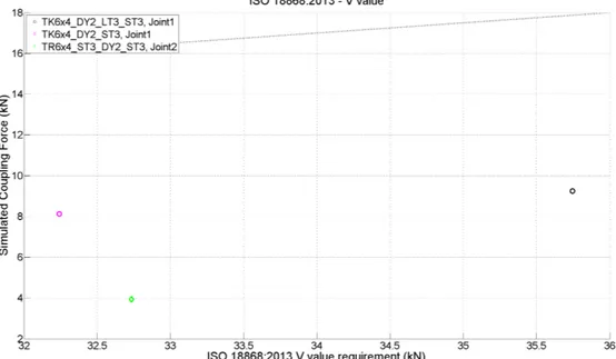
5.4. V-value comparison
Figure 5 depicts the V-values resulting from simulations of the test case described in section 5.1. The pink (ISO No.1) and green vehicles (ISO No.3) are already covered by ISO18868:2013, whereas the black vehicle (Truck-B-double) has been included for analysis in this report.
The equations for V-values are only dependent on drawbar length and the load on the axles of the dolly. When taking the same drawbar length for all vehicles the load on the dolly axles is the
determining factor for the V value. Having more weight on the dolly axles, the black vehicle naturally produces higher V values, as expected. When looking at the simulated force values, it is possible to see that the black vehicle also generates higher vertical forces on the joint than the other two vehicles. This shows that the requirement is computed in line with the magnitude of the forces expected in the new vehicle.
It is also worth pointing out that for the pink vehicle, the standard V-value requirement is lower than the requirement for the green vehicle combination, which is expectable since the latter has a higher load on the dolly axes. However, the simulated vertical forces are higher for the pink vehicle than for the green vehicle. This can be due to the nature of the vehicles ahead of the dolly since it would be expected to find a bigger range of pitch from the truck (pink combination), than from the semitrailer (green combination). This can place more stress on the joint given the increased range of relative displacement between the connected vehicles.
Figure 5 – Simulated joint vertical force (y axis) versus requirements from ISO18868:2013 (V values in x-axis). Each color represents a different vehicle. Marker shape identifies the joint number in the vehicle (circle - joint1, diamond - joint2, star - joint3). The dotted line represent half of the ISO requirement.
26 VTI rapport 1031A
6.
Discussion
Forces occurring in a coupling are characterized by different amplitudes and bandwidth depending on the nature of the stimulus the vehicle combination is exposed to. Braking, acceleration, and steering are normal stimuli a vehicle combination experiences under nominal conditions. These can, therefore, be used as references to classify the gravity of forces in a coupling under abnormal stimuli. In general, three different types of stimuli can be identified,
1. Lateral and longitudinal forces due to steering, braking, and accelerating.
2. Road borne disturbances i.e. road profile generating forces in the longitudinal direction. These forces are also dependent on the geometric layout of the vehicle combination.
3. Park and switchyard driving, i.e. maneuvering forces due to e.g. jackknifing or similar conditions.
Figure 6 Clevis coupling forces (and speed) of an A-double braking at 6 m/s2.
The first category includes the normal operation due to the road planar motion of the vehicle
combination, but can also include abnormal situations such as malfunctioning brake systems, etc. One of the main dynamic components is due to the pitching motion of the involved vehicles. An example of this is for a drawbar (Clevis) coupling of a braking A-double combination with constant retardation of 6 m/s2. A simulation reproducing these conditions is given in Figure 6, where the qualitative
behavior is captured. For the longitudinal force (blue curve), it can be observed that the main forces arise at standstill. At this point is the suspension dissipating the last energy of the braking force, creating an alternating stretch and contraction of the drawbar. This is a motion in an out-of-road plane, as opposed to the in-road-plane motion of braking and accelerating without the pitch will cause. It should also be noted here that simulating tyre behavior at low speeds is non-trivial, and the physical interpretation of a standstill case should be made with care.
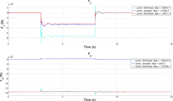
Figure 7 and Figure 8 depict the coupling reaction forces (opposite sign from Figure 6) of an accelerating and braking A-double vehicle configuration, respectively. The acceleration and braking are made to match (3 m/s2). It can be observed that the clevis coupling force is very small in the
braking case. This is due to the braking distribution, which is assumed to match the acceleration for all vehicles and actuated in the same instant. Any other brake distribution scheme will result in a different situation with different forces. Here, the braking strategy makes the fifth wheels take all the retarding forces. In the acceleration case, the first fifth wheel on the tractor is exposed to more force than the clevis and fifth wheel of the dolly converter, which both experience very similar forces. It is clear that a normative case should not rely on a specific braking strategy. A pragmatic way would be to simulate
the brake system as the worst possible way that the regulations admit with respect to delay in application between vehicles, conditions of pads, calipers, tires, etc.
Figure 7 Acceleration case for the A-double vehicle combination with an acceleration of 3 m/s2
Figure 8 Braking case for the A-double vehicle combination with a retardation of 3 m/s2.
The road borne disturbances, such as potholes, speed bumps, and road unevenness will generate forces in a similar fashion as for the braking case discussed above, with out-of-road plane motions. A sudden displacement of a leading vehicle due to a speed bump will create a stretching motion of the coupling of the following vehicle. In (Svensson et. al. (2016)) it is claimed that these road induced coupling forces dominate the forces in a clevis coupling. The claim is backed up with measurements from tests on test tracks and real traffic driving. It can be noted that these dynamic effects are local in the road train. They are not to any significant way dependent on the length of road train, i.e. number of vehicles or the total mass. It is, however, unclear in which situation maximum forces will be generated, e.g.
potholes versus unbalanced brakings, such as in equation 4. Ultimately, the normative cases should be selected using a balance of frequency and risk and should be well-grounded in statistics and
experience.
For low-speed maneuvers, such as parking or switchyard operations, articulation angles can be very high. These high articulation angles may even hit mechanical end stops, where the leading and trailing units meet outside the joint. The distance between the coupling force and the meeting point of the vehicles will act as a lever for forces driving an increase in the articulation angle. Forces generated here can be extreme. However, this situation may be regarded as misuse of the equipment and may not be relevant for the present investigation.
The ISO standard and new equations herein presented are based on the take-off situation where the leading vehicle is generating a propelling force. This scenario may not be the worst-case as discussed above, and other scenarios may be worse with respect to the coupling forces. Based on a combination of simulations and measurements, a thorough investigation is recommended to establish a worst-case scenario and a balance between the in-road plane and out of road plane forces at couplings. Previous discussions and figures indicate that fifth wheels might be dimensioned based on in-road plane motions while clevis couplings should be dimensioned on out-of-road plane motions.
The ISO standard is likely conservative in requirements, but not due to the nature of the considered scenarios. Conservativity is built into the expressions where an exaggerated force and other heuristic means are used to ensure generous safety margins. This results in a requirement without guarantees, since we are detaching ourselves from the nature of force generation. The standard provides loose guarantees for estimated force values, which in turn are masked by its conservative nature. The use of the existing standards for the existing combinations confirms in practice the conservativeness, without quantifying it.
A different approach should be taken, where the physical interpretation can be preserved in the derived expressions. However, the expressions need to be simple enough to be implemented in legislation and not depend on the parameters that are hard to obtain. Examples of this might be the dependence of suspension parameter for the out-of-road plane, and parameters describing the mounting assembly of the coupling, i.e. stiffness and damping for the in-road plane case. Hence, the problem of model complexity needs to be studied in parallel to the investigation of dimensional scenarios.
VTI rapport 1031A 29
7.
Concluding remarks
This report extends the existing ISO standard requirements for coupling forces to two new vehicle combinations: Truck-B-double and B-triple. Due to the semi-empirical nature of the existing ISO standard, means to validate the new expressions had to be developed. Simulations were employed to compare the coupling forces and coupling requirements of combinations both covered and not covered by the standard.
The comparison between results from the simulated joint forces, the ISO requirements, and the new expressions, suggest that the latter are in line with the expectations and should not be considered controversial as a base for legislation for the new combinations. This is also confirmed by coupling force requirements from the new expressions for vehicle combinations obeying the 74-ton
requirement.
The expressions presented in this report are grounded in the existing ISO standard in that they align with how the ISO expressions are formed and argued for. The semi-empirical nature of the ISO standard may potentially become problematic with the increased complexity of the vehicle
combinations; hence it is recommended that further investigations are carried out to define normative scenarios as well as expressions closely grounded on physical behavior and motivated assumptions.
VTI rapport 1031A 31
References
Sweatman, P. (March 1980), Strength requirements for tow couplings in road trains ARRB; AIR
1083-1, Australia
Sweatman, P. (December 1980), Instrumentation for measurement of coupling forces in road trains,
ARRB; AIR 1083-2, Australia
Sweatman, P. (1987), Strength requirements for fifth wheel couplings in road trains and general articulated vehicles.; Australian Road Research Board; Research report ARR 149, Australia
- Commercial road vehicles – Coupling equipment between vehicles in multiple vehicle combinations
– Strength requirements, ISO 18868:2013
- Road vehicles – Drawbar couplings and eyes for hinged drawbars – Strength tests, ISO 8718:2001 Svensson B., Nilsson, J. & Fröjd, N. (2016), CLEVIS COUPLINGS IN MULTI VEHICLE
COMBINATIONS. In the 14th International Symposium on Heavy Vehicle Transportation
Technology: 2016, New Zealand.
Kharrazi, S., Bruzelius, F., Sandberg, U. (2017) Performance based standards for high capacity transports in Sweden: FIFFI project 2013-03881: final report. Swedish National Road and Transport
ABOUT VTI
T
he Swedish National Road and Transport Research Institute (VTI), is an independent and internationally prominent research institute in the transport sector. Our principal task is to conduct research and develop-ment related to infrastructure, traffic and transport. We are dedicated to the con-tinuous development of knowledge pertaining to the transport sector, and in this way contribute actively to the attainment of the goals of Swedish transport policy. Our operations cover all modes of transport, and the subjects of pavement technology, infrastructure maintenance, vehicle technology, traffic safety, traffic analysis, users of the transport system, the environment, the planning and deci-sion making processes, transport economics and transport systems. Knowledge that the institute develops provides a basis for decisions made by stakeholders in the transport sector. In many cases our findings lead to direct applications in both national and international transport policies.VTI conducts commissioned research in an interdisciplinary organisation. Employ-ees also conduct investigations, provide counseling and perform various services in measurement and testing. The institute has a wide range of advanced research equipment and world-class driving simulators. There are also laboratories for road material testing and crash safety testing.
In Sweden VTI cooperates with universities engaged in related research and education. We also participate continuously in international research projects, networks and alliances.
The Institute is an assignment-based authority under the Ministry of Infrastruc- ture. The Institute holds the quality management systems certificate ISO 9001 and the environmental management systems certificate ISO 14001. Certain test methods used in our labs for crash safety testing and road materials testing are also certified by Swedac.