Mälardalen University
School of Innovation, Design and Engineering
Västerås, Sweden
Thesis for the degree of Bachelor of science in Engineering –
Aeronautics
15.0 credits
Aerodynamics and Structure of a Large
UAV
Oscar Vestlund
ovd13001@student.mdh.se
Examiner: Mikael Ekström
Mälardalen University, Västerås, Sweden
Supervisor: Jakob Brynolf
1
Abstract
This thesis investigates what design of a large UAV performing VTOL using only electrical motors is the most viable in terms of extending its range. Because it uses batteries for power, its powered time is limited, posing the need for a way of extending its flight time. By using a tiltwing design, its vertical flight time is cut at the same time as it will be able to perform as a glider, increasing its range
drastically. To achieve the best lift-to-drag ratio, the high-lift F3B RG15-airfoil was chosen, giving the UAV a lift-to-drag ratio of 36,48, and a maximum range per descend glide of approximately 25,5 kilometers. The fuselage will be a simple, aerodynamic body just big enough to hold the batteries and the load while giving the wing the ability to tilt without interfering with the rotors. The material used in this thesis comes from a company which produces high-strength carbon fiber tubes and rods as well as a 3k twill weave carbon fiber prepreg for the skin, making the structure as light and strong as possible. The result is an aircraft with a structural weight of 56,6 kilograms that is strong enough to lift with a combined weight of 495 kilograms and at the same time perform a safe glide flight.
2
Table of Contents
Glossary ... 5 1 Introduction ... 6 1.1 Motivation ... 6 1.2 Requirements ... 6 1.3 Problem Formulation ... 7 1.4 Research ... 7 2 Background ... 8 2.1 VTOL ... 82.2 Different types of VTOL ... 8
2.2.1 Tiltrotor... 8 2.2.2 Tiltwing ... 8 2.2.3 Gyroplane ... 9 2.2.4 Fan-in-wing ... 9 2.2.5 Vectored thrust ... 9 2.3 Example of Aircraft ... 9
2.3.1 Bell Boeing V22 Osprey ... 9
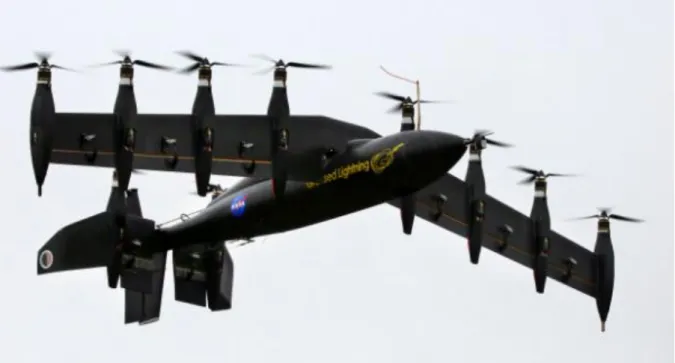
2.3.2 NASA GL-10 Greased Lightning ... 10
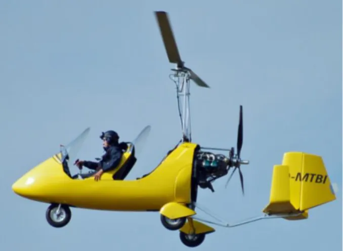
2.3.3 AutoGyro Calidus ... 10
2.3.4 Augusta Westland Project Zero ... 10
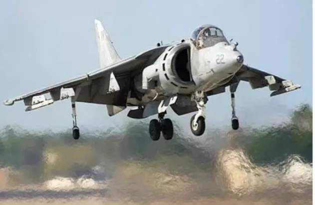
2.3.5 Lockheed Martin F-35b Lightning II ... 10
2.4 Airfoils in general ... 10
2.5 Airfoils of choice ... 11
2.5.1 CAL4014l (CLARK YH) ... 11
2.5.2 NACA 4301 2A ... 11 2.5.3 S1223 ... 11 2.5.4 RG15 ... 12 2.6 Material ... 12 2.6.1 Alloys ... 12 2.6.2 2024-T3 ... 13 2.6.3 6061-T6 ... 13 2.6.4 7075-T6 ... 13 2.6.5 7075-T73 ... 13 2.7 Carbon fiber ... 13 2.7.1 Prepreg ... 14 2.7.2 Hextow AS4C ... 14
3
2.7.3 3k Twill Weave Carbon Prepreg ... 14
2.8 Aerodynamic calculations ... 14
2.8.1 Lift ... 14
2.8.2 Drag ... 14
2.8.3 Zero-lift drag coefficient ... 15
2.8.4 Induced drag ... 17
2.8.5 Drag on the body ... 17
2.9 Mechanics ... 18 2.9.1 Bending ... 18 2.9.2 Shearing ... 19 3 Related work ... 20 4 Method ... 21 4.1 General ... 21 4.1.1 Lift ... 21
4.1.2 Zero-lift drag coefficient ... 22
4.1.3 Induced drag ... 23
4.2 Choosing airfoil ... 23
4.2.1 Wing design ... 24
4.3 Designing the Aircraft Fuselage ... 24
4.3.1 Fuselage - General ... 24
4.3.2 Dimensions and weight ... 25
4.3.3 Skin ... 26
4.3.4 Drag on the body ... 27
4.3.5 Stall speed ... 27
4.4 Rods to hold the motors ... 28
4.5 Wing ... 30 4.5.1 Form-giving Ribs ... 30 4.5.2 Longitudinal Spars ... 30 4.6 Vibrations ... 33 4.7 CFD Analysis ... 33 4.8 FEM-Analysis ... 34 5 Result ... 35 5.1 Wing Design ... 35 5.1.1 Airfoil ... 35 5.1.2 Inner Skeleton ... 35 5.1.3 Ailerons ... 35
4 5.1.4 Horizontal Stabilizer ... 35 5.1.5 Vertical stabilizer ... 36 5.2 Fuselage Design ... 36 5.3 Overall Design ... 36 5.4 Material ... 36 5.5 Performance ... 36 5.6 FEM-Analysis ... 37 5.7 Suggestions ... 37 6 Discussion ... 39 7 Conclusion ... 40 8 Future Work ... 41 9 Acknowledgements ... 42 References ... 43 A Appendix ... 46
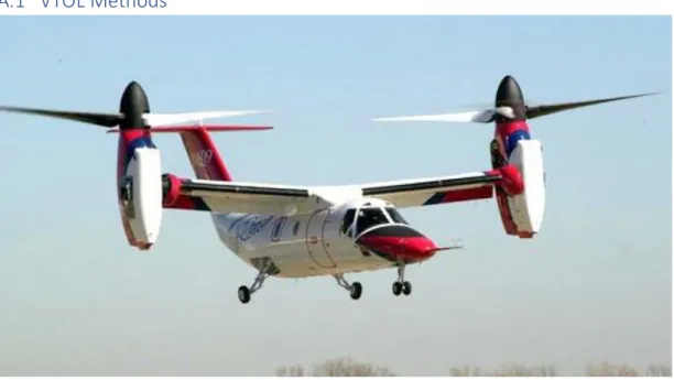
A.1 VTOL Methods ... 46
5
Glossary
AOA – Angle of Attack.
CFD – Computational Fluid Dynamics. CTOL – Conventional Take Off and Landing. ESC – Electronic Speed Control
FEM – Finite Element Analysis. FOD – Foreign Object Damage. MTOW – Max Take Off Weight
Outtime – The maximum time allowed at room temperature before it starts curing. STOL – Short Take Off and Landing.
STOVL – Short Take Off and Vertical Landing.
Tack Life – The time of which the prepreg will continue to have enough handling for component lay-up.
UAV – Unmanned Aerial Vehicle. USAF – United States Air Force. UTS – Ultimate Tensile Strength. VTOL – Vertical Take Off and Landing.
6
1 Introduction
The advantages of designing a remote-controlled aircraft capable of achieving VTOL are many. There are several ways this can be achieved, with different designs applying on each of them. This thesis aims at finding the most optimal method and then designing the structure of the aircraft. The most prominent methods aircraft capable of using VTOL use are tiltrotor, tiltwing, fan-in-wing and vectored thrust. The most common used are the tiltrotor, which have been proved works both in vertical and horizontal flight, where the motors are mounted on a fixed wing and can tilt to change the direction of thrust. Tiltwing uses fixed motors and a tilting. This is not as popular as using tiltrotor because of the loss of structural stability of the wing. If the motors would be built in the wing, it would be a fan-in-wing. The idea is that when the rotors are inside the wings, they’re protected against FOD and it reduces drag from them. It’s an excellent VTOL aircraft but is horrible in horizontal flight due to having to tilt the whole aircraft to achieve forward speed, like a helicopter. And just like a helicopter, the design is limited in both speed and efficiency. It could be combined with either of the designs mentioned above to create a hybrid with possible desirable benefits. However, this makes an already complex design even more complex, with just a slightly increase in efficiency. Vectored thrust is when a jet powered aircraft uses nuzzles to direct its air flow downwards to achieve vertical thrust. This is very unstable and isn’t really used more than a niche for some types of aircraft.
1.1 Motivation
Mälardalen University (MDH) has a project which is to create Naiads and want to build an UAV capable of serve as a delivery drone for up to three of these to remote locations. This project has been worked on for a while by students in the robotics and embedded systems programs as part of their project course. The current result is two smaller models which have been designed and built. The issue with these designs is that they haven’t been scaled properly in terms of aerodynamics and both have very limited flight time. Because of that, the aim of this thesis is to come up with a design which will perform as optimally as it can [1].
1.2 Requirements
There are several requirements and limitations which can influence the decisions while designing the structure. These include:
• The UAV must be able to perform a complete VTOL. STOL or STOVL is not accepted. • The UAV must be able to glide with its motors shut off.
• The motor power will be purely electric.
• The UAV should have the possibility to land both on land and water.
• The freight will consist of three naiads that weigh 33 kilograms each, which means that the UAV must be able to lift approximately 100 kilograms of load.
• The maximum weight of the whole UAV including the Naiads must be below 495 kilograms. • The minimum range of the UAV is 5 kilometers, but the target range is 25 kilometers. The first item on the list means the it will take off and land similar to a helicopter. This will put great stress on a wing construction, meaning that a wing has to be incredibly strong or able to tilt to reduce the force acting on it.
The second item means that the UAV will have to have some sort of forward facing thrust. Because the motor control system is not relevant for this thesis, only a suggestion will be made for this.
7
The third item means that there is a limit in power over time for the UAV because of the low energy density of batteries compared to petroleum-based fuel. This makes the designing of the UAV for glide flight very important.
The fourth will make a strong impact on what material which to use. Because some commonly used aircraft materiel either isn’t water proof nor water resistant, this have to be though at.
The fifth item explains itself. Some sort of shipping mechanism has to be included in the design. This will be discussed with the students working on the Naiad to come to a common consensus.
The sixth item comes from the Swedish department of transportation, stated that if the UAV will be classed as an ultralight aircraft, it can’t weigh more than 495 kilograms [2]. This classification is highly desirable due to there being fewer restrictions on ultralight aircraft compared to heavier ones. Because this is highly possible to achieve, that will be the goal of this thesis.
The last item means that wings is a complete must. The most important aspects of a good glider are the design of the airfoil and its aspect ratio, which will be explained when choosing the airfoil.
1.3 Problem Formulation
The UAV would be able to be powered only with internal power in the form of batteries which limits the power received and the time which it is able to fly, while at the same time being able to perform VTOL. The expected problems to appear is how to design the wings and body to make as little use of its motors as possible, allowing for a longer flight. This includes choosing the VTOL method best suited, designing the wings so it makes the best use of its limited time with powered flight and to reduce drag overall on the aircraft. The other obvious problems include limiting the weight but at the same time keep the safety in the structure and come up with a design that isn’t overly complicated to work with in later projects.
The design of the UAV can be divided into two parts. First the aerodynamic part, which will be worked with to reduce the drag on the UAV to make for a longer flight time, and thus, a greater distance. The second part is the mechanics where the interior structure of the UAV is designed to make for a stable structure.
1.4 Research
While there are set goals for this UAV project, where this thesis aims to fulfill some of them, there are scientific parts of it too. The research aspect for this thesis will be to investigate to see if there is a possibility to design a large UAV capable of performing VTOL using just electrical motors that is viable to operate.
8
2 Background
The background section will explain the state of the art. It will be divided into three sections. One section will be used for explaining the theory of the different methods of VTOL. The second section will give examples of aircraft using the different methods to give a general understanding of how VTOL aircraft work. The third section will explain general aerodynamics, mechanics and choosing of material.
2.1 VTOL
VTOL is not a new concept in aviation. There already exist several aircraft relying on different kinds of methods of achieving VTOL. The most well-known aircraft to make use of VTOL is the helicopter, which uses its main rotor on its roof to push a downwards facing airstream, resulting in vertical lift-giving thrust. This makes it a lot more versatile than a conventional airplane due to not needing a runway to take off from. The disadvantage is its speed and therefore, range. The speed limit is due to a phenomenon called dissymmetry of lift, which occurs due to rotors acting like rotating wings. When moving forward, the advancing blade is experiencing more lift than the retreating blade. This will cause the dissymmetry of lift. Manufactures have designed the blades, so they flap, evening out the lift. If the helicopter’s speed is too high though, the flapping will be too great, resulting in it stalling [3]. Because of that, this thesis will only look at airplanes that can achieve VTOL. Normal airplanes aren’t capable of VTOL and needs a runway to achieve sufficient speed to produce the lift over the wings. This makes the airplanes faster with longer range, and better fuel efficiency. However, in some cases it is preferred that a long runway is not needed for an aircraft to take off, and thus, STOVL and VTOL aircraft was developed. VTOL aircraft has the advantage that they can take off without the need of a runway, they have better maneuverability and they have better horizontal flight control than conventional aircraft. There are several ways to achieve VTOL on an aircraft, which will be described in the next section.
2.2 Different types of VTOL
There are several ways of achieving VTOL, each with its own advantages and disadvantages. This thesis will cover the most well-known and most used types to get a general understanding of the concept of VTOL aircraft. These include tiltrotor, tiltwing, gyroplane, fan-in-wing and vectored thrust.
2.2.1 Tiltrotor
An aircraft with tiltrotors achieves VTOL by tilting its rotors. When flying vertically, the rotors are facing upward, like a helicopter. When switching from vertical to horizontal flight, the rotors are rotating forward to make it look like a conventional airplane, with control surfaces on the wings for control and stability. Some tiltrotor aircraft are even able to move their rotors independently. The main advantage of a tiltrotor aircraft is its ability to fly fast and be able to do VTOL with the
performance and efficiency compared to some helicopters [4]. The disadvantages compared to other ways of VTOL include more complex motor systems compared to stationary motors due to the need of rotation, with a slower transition time from vertical to horizontal flight. It also has a limited design due to the rotors interfering with the wings to produce unwanted wake vortices, lowering the efficiency [5][6].
2.2.2 Tiltwing
A tiltwing aircraft works the other way than a tiltrotor. Instead of having rotating rotors and a fixed wing, the rotors are fixed on the wing and the whole wing rotates. The main advantage with this
9
method is that when in horizontal flight, it behaves just like a normal plane. And because the slipstream from the rotors strike the wing at its leading edge instead of its upper surface, a tiltwing don’t lose as much thrust to interference from the wings as a tiltrotor. Because the rotors are stationary, and only the wing tilts, the motor system is simpler. The disadvantages are that it isn’t as stable during its vertical flight as other types of VTOL aircraft and its transition time is longer due to its lack of stability [7][8].
2.2.3 Gyroplane
Also known as an autogyro, is a sort of aircraft that takes advantage of a phenomena called
autorotation to provide lift and a common propeller to provide thrust. Autorotation is when a rotor is turning just by taking advantage of the air flowing up through the rotor, without the power of an engine. This will reduce fuel consumption and is a way of redundancy in case of a motor failure. During vertical flight, the main rotor will provide the lift needed, and in horizontal flight, it will autorotate. The advantages of this design include simple design, fast transition between vertical and horizontal flight and great redundancy. Some disadvantages are that, like helicopters, gyroplanes are affected by asymmetry of lift, and if wings are present, they can interfere with the main rotor [9].
2.2.4 Fan-in-wing
The idea of using a fan-in-wing configuration is that when the rotors are integrated in the wing of the aircraft, they’re protected against FOD, while at the same time reducing the drag induced from the rotors. At the same time, it doesn’t have the problem with the wing being in the way for the rotors, which would result in a loss of lift. However, because it is built into the wing, it runs the risk of creating problems for the inflow to the rotor. During vertical flight, it acts like a multirotor aircraft (a quadcopter is also a multirotor aircraft), but when it transits to horizontal flight, it experiences the same problems a helicopter would, meaning that it has to tilt its whole body to gain any forward momentum, which is very inefficient. This problem can be troubleshooted if it is used together with a tiltrotor or tiltwing design, but it’s a new and fairly untested design with new problems including that building such a configuration makes for an exponentially increased difficulty in motor design [10] [11].
2.2.5 Vectored thrust
These examples above is only viable using a propeller-driven engine, but what about jet engines? Their solution is called vectored thrust. This method has several ways of working, the most used include tilting the outlet of the jet engine, rotate the whole engine relative to the aircraft and using paddles inserted in the exhaust flow. Being still a jet motor, it possesses the usual advantages and disadvantages they have, being very fast but burning a lot of fuel. Because the aircraft basically is “blasted” vertically, it has very poor control, although for the same reason, it has a very fast
transition from vertical to horizontal fight. This thesis won’t consider this option due to it needing the motors to be completely electric [12] [13] [14].
2.3 Example of Aircraft
This section of the thesis will show the practical uses of the VTOL methods discussed in 2.2 with an example aircraft per method.
2.3.1 Bell Boeing V22 Osprey
Probably the most known aircraft capable of doing VTOL, being used in the US Marine Corps and the USAF. It is a tiltrotor aircraft and is designed by having one motor on each wingtip, which gives as
10
good vertical control as possible. As mentioned above, being a tiltrotor, the design loses some lift due to having the rotors placed above the wings. However, it can reach a maximum speed of 500 km/h, a range of 200 nautical miles (370 kilometers) for the Marine V-22, and a range of 500 Nautical miles (926 kilometers) for the Air Force’s. Having quite large turboprop motors, it has a fast transition time of less than 30 seconds, but also great fuel consumption [6][4].
2.3.2 NASA GL-10 Greased Lightning
The Greased Lightning is a tiltwing project conducted by NASA at the time of writing this thesis. It has a prognosis of being finished in 2020, with smaller models already being built. It features ten
electrical engines, has a goal of beating the already existing tiltrotor and tiltwing aircraft in efficiency and will probably be the closest UAV in similarity with this project. The data available predicts it having a MTOW of 125 kilograms, and a wingspan of 6,34 meters [15].
2.3.3 AutoGyro Calidus
The AutoGyro Calidus is a German autogyro. it’s well-known for its high cruise speed and long range, which is 160 km/h and 800 kilometers respectively. Being an autogyro, it only obtains a glide ratio of 1:3 though. The maximum capacity of the Calidus is two peoples (one crew and one passenger) [16].
2.3.4 Augusta Westland Project Zero
This is a hybrid between a tiltrotor and a fan-in-wing aircraft which at the moment of writing this thesis is in the testing phase. It, like the UAV this thesis is based on, is only using electricity in the form of onboard batteries as its source of power. Because of this, is has a very short flight time, which is why there are plans to install a diesel engine to further improve its time in the air. Test flights have proven the concept by showing that the prototype can hover at least [17] [18].
2.3.5 Lockheed Martin F-35b Lightning II
The F-35 is a fifth generation multirole, stealth fighter which comes in three models (a, b and c), one being a STOVL variant. This is the most up-to-date aircraft which is using vectored thrust, and this is possible thanks to the Rolls-Royce LiftFan propulsion system, which sacrifice a third or the fuel tank from the conventional F-35a to make it possible. This works because the jet force is directed via a driveshaft and clutch of 29000 shaft-horsepower to drive a 50-inch two-stage fan able to generate more than 18000 lbs. of thrust in the front. In the back, the jet thrust can be directed via a swiveling jet pipe while the compressed air can be bleeded out in the wings using Rolls posts. These generate a combined thrust of 22000 lbs. [19] [20].
2.4 Airfoils in general
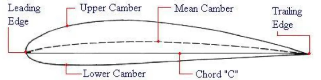
An airfoil is the cross-section of a wing. It is used when calculating the lift generated by the wing and to show the airflow around the wing. When describing the shape and size of an airfoil, normal units are not used. Instead, it uses dimensioning relative to itself (see figure 1). The most important aspects of an airfoil for airplanes is its AOA, camber (in % of the chord) and the placement of the maximal camber thickness. The airfoils that sailplanes often use are usually referred to as thermal
11
duration airfoils, meaning they make use of thermal columns to extend their flight time.
Figure 1. The terminology of an airfoil
The data used in this thesis will be taken from wind tunnel tests conducted by the University of Illinois and the software used will consist of DesignFoil and AirfoilTools.
2.5 Airfoils of choice
The wings are probably the most important aspect of this thesis. Its design will directly correspond to the distance the UAV will be able to glide. The data for the airfoils this thesis will cover will be taken from wind tunnel tests conducted by the University of Illinois and the software used will consist of AirfoilTools. The case study made gave several airfoils worth to consider [21] [22].
2.5.1 CAL4014l (CLARK YH)
The CAL4014l Is a reflexed flying-wing airfoil, which means that the trailing edge is deflected slightly upwards. It has a wide lift range, a generous thickness and predictable stall characteristics. This makes the CAL4014l a great all-purpose airfoil.
Figure 2. CAL4014l
2.5.2 NACA 4301 2A
The NACA 4301 2A is used on the one seat, mid-wing Schweizer SGS 1-26 glider and the two seated, high-wing Schweizer SGS 2-33 and has proved to be successful in both models.
Figure 3. NACA 4301 2A
2.5.3 S1223
The S1223 has been extensively tested in different reports of low speed airfoils. It is able to obtain very high cL,max (about 2.2) in the absence of slats or flaps because the design favors aft loading.It
12
Figure 4. S1223
2.5.4 RG15
The RG15 is an interesting airfoil in that it is a F3B (the Formula-1 for sailplanes) airfoil and by that, it has a lower lift compared to the other thermal duration airfoils, which sailplanes often use, but still works better thanks to it having better performance in both speed and duration tasks, which directly corresponds to its list-to-drag ratio.
Figure 5. RG15
2.6 Material
The material considered is widely used in the airline industry and have been tested loads of times, giving them very exact data and good reliability. This thesis will look at the aluminum alloys 2024-T3, 6061-T6, 7075-T6 and 7075-T73, as well as the carbon fiber matrixes Hextow AS4C and 3k Twill Weave Carbon Prepreg which have different properties in UTS, shearing strength, density and cost of manufacturing.
2.6.1 Alloys
An alloy is a mixture of different metals combined for different purposes. It may range from getting the desired properties of a certain element to reduce the overall manufacturing cost. Aluminum alloys are used extensively in the airline industry due to their high strength-to-weight ratio. Because of that, this thesis will just consider aluminum alloys as a metal. The aluminum alloys follow an ANSI standard, by its number and letter use which is structured as ABCC-X, where
• A is the alloy group (it shows what other major element the aluminum is alloyed with) • B indicates modifications in impurity limits. If B is zero, there aren’t any special control on
individual impurities (this should only be used in cases where the risk of impurities is predominant. The number 1-9 indicate special control of one or more individual impurities. • CC are arbitrary numbers used purely to identify the different alloys, with the exception of
the 1xxx series, where it shows the specific minimum aluminum content in a hundredth of a per cent over 99% instead. (1050 would show an aluminum content of 99,50%)
The X is a bit more complicated, but for the sake of this thesis, a simple explanation is presented. It’s divided into five subcategories where it is shown if an alloy is As Fabricated “F”, Strain Hardened “H”, Thermally Treated “T”, Annealed “O”, or Solution Heat-treated “W”. The Strain Hardened and
13
Thermally Treated designations can be further divided into subdivisions where the Strain hardened designation can be written as HXY where
• X indicated a basic operation like if it’s lacquered/painted, stabilized (over aged), or partially annealed.
• Y indicates the degree of strain hardening, ranging from 2-8 (quarter hard – Full hard) to 9 – Extra hard.
The Thermally Treated subdivision explains the process of how its heated and aged. These can include additional digits too, indicating different kinds of stress relief, like stretching or compressing. Finally, some alloys can be cladded with different materials to make them water resistant [23] [24]. The chosen alloys for this thesis will serve as examples. The data for these alloys are taken from a database which provides data from the manufacturers of the alloys to their customer, which include Boeing, NASA, Bombardier and GKN Aerospace [25].
2.6.2 2024-T3
The 2024-T3 alloy is an aluminum-copper alloy which have been solution heat-treated, cold worked and naturally aged. It’s popular in applications requiring a material with high strength and low weight, being widely used in aircraft structure. The 2024 alloy in general has the highest tensile strength relative to other 2000-series alloys. It has an Young modulus of 73,1 GPa, a density of 2780 kg/m3 and a tensile yield strength of 345 MPa [26].
2.6.3 6061-T6
6061-T6 contains magnesium and silicon as its primary alloying elements. It has been solution heat treated and artificially aged. because it is widely available and good workability, it’s one of the most used alloys to date [27]. Although the tensile strength is not as great as other alloys, it’s more easily worked with and is more resistant to corrosion. The Young modulus is 68,9 GPa, the density 2700 kg/m3 and the tensile yield strength is 276 MPa [28].
2.6.4 7075-T6
The 7000 series of aluminum alloys contain zinc as its primary alloying element. Although expensive to use, it has a strength comparable to many steels. That’s why it’s used in applications as aircraft shafts and gears. Like 6061-T6, it has been solution heat treated and artificially aged. It has an Young modulus of 71,7 GPa, a density of 2810 kg/m3 and a tensile yield strength of 503 MPa [29].
2.6.5 7075-T73
Is also an aluminum-zinc alloy which is solution heat treated and stabilized to a certain temper (the T-73 temper to be specific.) This makes it stronger against stress corrosion while keeping most of the strength the same as other 7075 alloys. This makes it a good combatant to 7075-T6 to use on components exposed to constant stress. Its Young modulus is 72 GPa, its density 2810 kg/m3 and its
tensile yield strength is 435 MPa [30].
2.7 Carbon fiber
Carbon fiber is long, thin strings of fibers made of carbon. They are produced by bonding carbon atoms in crystals that are close to aligned to the axis of the fiber. Due to the crystal-like structure, this gives carbon fibers its ridiculous high strength compared to its size. If the fibers are combined with plastic resin and baked it forms a carbon fiber reinforced polymer, and if the manufacturer
14
combines a fiber and a matrix, it’s called a Pre-impregnated material (prepreg), which this thesis will use [31].
2.7.1 Prepreg
As mentioned above, a prepreg is a resin matrix system that are reinforced with different fibers. This thesis will only take interest in carbon fibers, mainly because of its relevance and time restraints. A prepreg can be made where all fibers are in the same direction, giving one direction of reinforcement (unidirectional), or where it’s laid out like a sheet, giving several directions of reinforcement (fabric form or twill weave). This means that if the application only needs to withstand one type of force, a unidirectional prepreg is to prefer due to the weight saved by not adding extra layers. If the
application however, would be subject to forces in several directions, like the UAV, a twill weave is used. The main advantages of using prepreg is that a sheet can be laid into a mold without using additional resin, which would run the risk of weakening the fibers. It’s also less wasteful because it isn’t impregnated by hand, wasting any resin or fibers. This means also that there aren’t any resin-rich nor dry areas which would alter the prepregs’ strength
2.7.2 Hextow AS4C
Hextow AS4C is a carbon fiber specifically produced for the aerospace industry. It’s available in both 3k, 6k and 12k, which is a measure on how many filaments there are per fiber and has a fiber content of 60% [32]
2.7.3 3k Twill Weave Carbon Prepreg
This prepreg is also a combined twill weave carbon fiber and epoxy resin which is mixed to 37% resin content, maximizing the strength properties of the fabric according to the company. It has a standard thickness of 0,012” (0,3048 mm) and a width of 50” (1,27 meter) [33].
2.8 Aerodynamic calculations
The aerodynamic calculations will mainly be used to calculate the behavior of the UAV while in flight. This include everything from the lift force it feels to the drag created by the air molecules dragging along the fuselage when in glide flight.
2.8.1 Lift
The minimal lift is calculated during which the UAV is gliding. It will be set at its max altitude which is predetermined to be 1000 meter, where the lift will be lowest. It’s calculated using the formula
𝐿 =𝑠𝜌𝑐𝐿𝑣
2
2 (1)
• L is the lift in Newton, which is equal to the weight of the UAV.
• s is the area of the wing which is calculated as the width of the wing times the chord. • 𝜌 is the density of air at 1000 meters [34].
• 𝑐𝐿 is the coefficient of lift.
• v is the horizontal speed.
2.8.2 Drag
When designing a sailplane, it’s extra important to reduce the drag as much as possible. This can be done in several ways, but the most useful and what this thesis will focus on is the design of the wings. The formula used is
15 D =sρcDv
2
2 (2)
Where the wing area, density of air and velocity is the same as in equation (1). Here the coefficient of drag - cD is calculated further due to containing several coefficients itself.
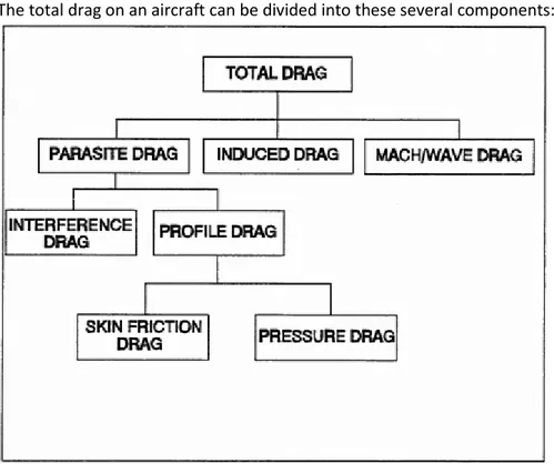
cD= cD,0+ cD,i (3)
• cD,0 is the zero-lift drag coefficient which is reflective of the aircraft’s parasitic drag (profile drag)
• cD,i is the lift-induced drag coefficient
The total drag on an aircraft can be divided into these several components:
Figure 6. Different drag classifications
2.8.3 Zero-lift drag coefficient
The zero-lift drag coefficient cD,0 directly corresponds to an aircraft’s drag due to viscous effects,
meaning that it describes how streamlined an aircraft is [35].
The zero-lift drag can be divided into two subparts describing the total drag due to pressure and friction.
D0= Df+ Dp (4)
• D0 is the total drag caused by viscous effects.
• Df is the drag due to skin friction, which will be the dominant drag for a turbulent system. • Dp is the drag due to separation of the air from the wing (pressure drag).
In the same way, the coefficients for the different drags listed above has the same relation to each other
16
cD,0= cf+ cp (5)
Because the skin-friction coefficient depends on whether the air moving over the wing is laminar or turbulent, there are one formula for each.
CfLaminar = 1,328 √Rexcr (6) CfTurbulent = 0,074 Rex0,2cr (7)
Because of viscosity, the airflow over the surface of the wing will adhere to the surface due to friction between the air molecules and the wing surface. This will create a region of which the air will be affected by its viscosity. That region is called the boundary thickness and just like the skin-friction coefficient, it depends on whether it’s a laminar or turbulent flow.
δLaminar= 5,2xCr √Rec (8) δTubulent = 0,37xCr Rec0,2 (9)
Where xcr is the length to the critical point of which the laminar airflow turns into turbulent, and Re
is the Reynolds number.
The Reynold’s number is the ratio between the inertial force and the viscous force of a medium and is used to predict the transition from laminar to turbulent flow in a certain medium. It’s used when calculating the skin-friction drag on a body and uses the formula
Re =ρvL
μ (10)
• ρ is the density of the medium (air for aircraft.)
• v is the velocity of the medium with respect to the wing.
• L is the characteristics length (in this case, the length of the cord.) • μ is the dynamic viscosity of the fluid.
Equations (6), (7), (8) and (9) shows how it would look in a pure laminar or pure turbulent
environment, but somewhere on the wing, as stated above, at a critical point xcr, the laminar flow
will become turbulent. It’s calculated using by rewriting (10). xCr=
μRexcr
ρv (11)
Here Rexcr is the critical Reynold’s number, where the inertial force overcomes the viscous force,
17
Using equation (11), it’s possible to more thoroughly calculate (6), (7), (8) and (9) becoming: δLaminar= 5,2xcr √Rexcr , δTurbulent= 0,37(c − xcr) Rec−x0,2cr (12)
Knowing the point of transition, the complete coefficient of skin friction can be calculated by combining equation (6) and (7). This is done by knowing that before the point of transition, the flow will act as a laminar layer, and after it will be completely turbulent. This will be visualized in figure 17 [36]. cf,tot = 1,328 √Rexcr + 0,074 Rec−x0,2cr (13)
2.8.4 Induced drag
While the profile drag is something that really can’t be eliminated, the induced drag is geometrically related, and because the geometry of the wing will be the same regardless of the design of the airfoil, it will be the same for all
cD,i =
cL2
πARϵ (14)
• AR is the aspect ratio of the wing (it’s calculated using bs2 where b is the wingspan and s is the wing area, which is 12,5 for the UAV).
• ϵ is the Oswald efficiency number and describes the change in drag in a realistic wing compared to an ideal, elliptical wing with the same AR (usually 0,7 < ϵ <0,85) [37].
The Oswald efficiency number is very complicated to calculate but can be estimated on low Reynolds number aircraft as [38]:
ϵ = 1
1,05 + 0,007πAR (15)
2.8.5 Drag on the body
Just like for the wings, equation (2) and (3) can be used to determine the drag caused from the body as well.
The zero-lift drag coefficient for the fuselage can then be found using the formula cD,0=
Swet
Sfuselage
cf (16)
where Swet is the wetted area, meaning the area which is in contact with the airflow and Sfuselage is
the area of the fuselage projected from above (top-view). A good visualization of the wetted area is that this is the area that would get wet if the fuselage would be submerged in water [39]. Because the skin-friction coefficient is just a part of the zero-drag coefficient, the quota of the areas must be greater than, or equal to one.
The airflow over the fuselage can be assumed to be completely turbulent. This means that the equation for the skin friction drag will look different, and will be corrected to be more precise for flat surfaces, like the fuselage [40].
18 cf=
0,455
(log10Re)2,58(1 + 0,144M2)0,65 (17)
This means that the Mach number has to be calculated. This is done by dividing the speed of the UAV by the relative speed of sound M =u
a. Here a is calculated using a = √RTκ where R and κ can be
assumed to be constant at this altitude and velocity and T is the standard temperature at the altitude of 1000 meter.
2.9 Mechanics
The mechanics is a very important part of this thesis due to some of the requirements and limitations stated in 1.2. Because the weight limit is strict, it is crucial to have as light material as possible that still is able to withstand the forces experienced during flight. This part covers the mechanics physics necessary to ensure a secure structure.
2.9.1 Bending
Understanding the bending of a beam or rod is crucial for designing a robust structure. These equations vary depending on the way the force is applied. If a weight is hung from the edge of a rod, the force will be concentrated to a single point, making the deflection w look like
w(x) =PL 3 6EI( 3x2 L2 − x3 L3) or w(L) = PL3 3EI (18) • P is the force applied.
• L is the length of the rod.
• E is the Young modulus, which describes the stiffness of a material.
• I is the area moment of inertia, which is the structure’s resistance to deflection. • x is the length of the system of choosing.
The area moment of inertia is depending of the shape of the structure. This thesis will be using the equation for thick, circular tube, which look like
I = π 64(D
4− d4) (19)
Where D is the outer diameter of the rod and d is the inner diameter.
If the force would be applied evenly over a structure, as with the lift on the wing, the formula will look like: w(x) = qL 4 24EI( x4 L4− 4x3 L3 + 6x2 L2 ) or w(L) = qL4 8EI where q = P L (20)
These equations show the distance of which the structure would bend, and by deriving them, the angle which they will be bent is obtained. Deriving (18) gives:
w′(x) =PL 3 6EI( 6x L2 − 3x2 L3 ) or w′(L) = PL2 2EI (21)
And by deriving (20), the angle for an evenly applied force is obtained. w′(x) =qL 4 8EI( 4x3 L4 − 12x2 L3 + 12x L2 ) or w ′(L) =qL3 6EI (22)
19
2.9.2 Shearing
Because a material can only be bent a certain amount before breaking, this is important to calculate. It’s done using the formula for the maximum normal stress
σ = M Wb
(23) Where M is the maximum bending moment in the structure, and Wb is the rotational resistance and
is calculated as:
Wb =
I
zMax (24)
Were, I is calculated in (19) and zMax is the maximum distance on the z-axis, which is translated to
20
3 Related work
This project has an already developed motor system, of which this thesis uses data from in the form of its weight and thrust generated. Otherwise, building an UAV this size using VTOL with pure electrical power is unheard of, and especially when using any of these designs explained in section 2.2. The only large UAV using any of these designs is the NASA GL-10 Greased Lightning, which is by the time of writing this thesis in its test phase. And even it uses diesel hybrid motors for power.
21
4 Method
This section of the thesis will use the general theories and equations stated in 2 and calculate what is relevant for a good general understanding and by that, a precise result.
4.1 General
Because the UAV is purely driven by batteries which have low energy density, its flight time is severely limited. Earlier work shows it just has battery power for 7.5 minutes of flight. To optimize the range of which it can fly, something more than just battery powered flight must be implemented. There are two ways this can be achieved, the first is to extend the power supply using solar panels. The second, of which this thesis will be based around is to make the most effective use of its motors. That means using the motors to ascend to a predetermined altitude and glide with the motors shut off to save power. When it reaches a minimum altitude, the motors will be powered on again and the cycle will repeat for as many times the power allows it to. This means the wings should have a similar design as other conventional sailplanes have, which means a long wingspan and a short cord relative to the area. This is because the cord highly determines the lift-to-drag ratio [41]. To choose the size of the wings, the weight must be calculated. The maximum and target total weight of the UAV is 495 kilograms, which comes from the Swedish department of transportation. Here it is stated that amphibious aircraft weighting less than 495 kilograms is classed as an ultralight aircraft. This classification is desirable due to there being fewer restrictions placed on ultralight aircraft [2]. Designing the UAV can be divided into two parts. The first is the aerodynamics and the second is the mechanics. The aerodynamics will include choosing an airfoil design, calculate the lift and drag for the wings, calculate the total drag induced by the entire UAV and calculate the lift-to-drag ratio for the UAV. This is done to see how long the UAV can glide at a maximum. The mechanics part will make use of several calculations to establish the strength, maximum shear, the bending of the different structures and whether a suggested material is strong enough to handle the forces or not acting on the structure. Because the wing design must be made before the body and wing
mechanics, the aerodynamics part of the wing will be made first, in the order of calculating the lift, calculate the drag from the airfoils, choosing the optimal airfoil and designing the complete wing. This will be followed by the aerodynamics and mechanics for the fuselage, the rods which will hold the motors and lastly, the wing mechanics due to it relying on the weight and drag of the rest of the fuselage.
4.1.1 Lift
When calculating equation (1) using the known parameters • L is the weight of the UAV
• ρ is 1,1117 kg/m3
• The area of the wing will be 8 m2
• v is 38,87 m/s.
It is possible to determine that the minimum cL has to be 0,724. Earlier calculations using the
equation for lift have shown that to maintain stable flight, a wing area of 7,1 m2 is necessary. That was however made with the assumption of having a cL of 0,8 using a general approximation for
22
4.1.2 Zero-lift drag coefficient
The zero-lift coefficient can easily be determined by the use of the graphs provided by AirfoilTools. Using the graph that shows cL and α, it’s possible to determine at what AOA the lift is 0. With this α
in mind, moving over to the graph showing its relation to cD, its value using the same α shows the
zero-lift drag or profile drag. Listing the zero-drag coefficients for the different airfoils shows: • CAL4014l - cD,0= 0,01
• NACA 4301 2A - cD,0 = 0,015
• S1223 - cD,0= 0,1
• RG15 – cD,0 = 0,0075
Even though the coefficient is obtained, it’s still very important in the understanding how the skin of the airfoil will behave in the airstream. Although the theory behind the exact calculations is beyond this thesis, a good estimate is that the critical point xCr will occur where Rexcr = 5 ∗ 105 and by
using equation (11), it gives that the critical point will occur 0,1878 meters from the LE. This gives that Rec−xCr = 1,669 ∗ 106 [43].
Using this is (13) in turn gives a total coefficient of skin friction of 0,0061. This can be summarized in this table:
Airfoil type cD,0 cf cp
CAL4014l 0,01 0,0061 0,0039
NACA 4301 2A 0,015 0,0061 0,0089
S1223 0,1 0,0061 0,0939
RG15 0,0075 0,0061 0,0014
Table 1. Coefficients of friction- and pressure drag for the different airfoils.
Equation (12) show that δLaminar= 0,0014 m and δTurbulent= 0,013 m. This shows that the
turbulent boundary thickness is approximately ten times larger than the laminar layer, meaning that if any additional control surfaces would be added, this needs to be taken into consideration to limit the interference.
Equation (13) also gives the ability to calculate the total skin friction drag for better visualization using the formula
Df =
ρscfv2
2
(25) • s is the area affected by the airflow, which is both the top and bottom of the wing (8*2 in this
case)
23
This makes for the interesting observation that two airfoils have higher coefficient of pressure, while the other two have a higher coefficient of friction, showing the difference what the choice of airfoil does.
4.1.3 Induced drag
To calculate (14), (15) has to be calculated first. This gives the UAV an Oswald efficiency factor of 0,7548, making it possible to calculate cD,i= 0,0277 from formula (14).
This means that all of the coefficients necessary is known. The table below shows coefficients for the different airfoils. Airfoil cD,0 cD,i cD CAL4014l 0,01 0,0277 0,0377 NACA 4301 2A 0,015 0,0277 0,0427 S1223 0,1 0,0277 0,1277 RG15 0,0075 0,0277 0,0352
Table 2. The different total coefficient of pressure for the different airfoils.
4.2 Choosing airfoil
Now when all the drag is calculated, the true lift can be estimated. By looking at the pictures 18 - 21, a true cL for a given cD can be read.
Because the airfoils came out to have several individual aspects, a lot of thought will be put behind the choosing. The first part will be to simply look at the lift-to-drag ratio. This ratio is interpreted as how many meters the aircraft will move horizontally for every vertical meter lost due to gliding, which will be 700 meters. For this UAV to make the target range of 25 kilometers, it needs to have a lift-to-drag ratio of at least 17,85, and that is assuming no time waste and two perfect cycles. A practical minimum for the ratio will thereby be 20. Using equation (1) and (2), the ratio between the lift and the drag is at the same time the ratio between the coefficients of lift and drag. With the help of this, the distance for each airfoil can be calculated too. This can be summed up in this table.
Airfoil cL cD cL/cD Distance in meters
CAL4014l 1,4 0,0377 37,14 25998
NACA 4301 2A 1,55 0,0427 36,3 25410
S1223 2,1 0,1277 16,44 11508
RG15 1,4 0,0352 39,7 27790
Table 3. The lift-to-drag ratio of the different airfoils.
This shows that the S1223, despite having the highest cL by a good margin is nowhere close to the
other airfoils in distance, leaving the other three left. The next thing to look at is the specific
24
NACA4301 2A has been used on two already produced gliders and the RG15 has the best range out of all airfoils. The predictability doesn’t mean very much when you shouldn’t stall on a VTOL aircraft in the first place and because this isn’t a pure glider, the CAL4014l and NACA 4301 2A doesn’t really have any good niches for this thesis. This combined with being the airfoil with the best lift-to-drag ratio and having the simplest design, the airfoil of choosing will be the RG15, showing the importance of having low drag on a wing. By looking at picture 21, it’s shown that it will obtain this lift-to-drag ratio at an AOA of 12°.
4.2.1 Wing design
Because the aircraft is using VTOL as its mean of ascending. The big area of the wing might pose a problem when lifting, resulting in loads of extra, unnecessary drag. Having a wing that could tilt upwards would get rid of loads of that extra drag, resulting in a faster ascend, and by that, less powered flight time while at the same time save the material loads of stress, eliminating the risk of fatigue. Because of the predetermined design, the engines aren’t mounted on the wing. This means that the main problem described in section 2.2.2 doesn’t occur. The amount of drag eliminated could be calculated using a rewriting of (2).
ηtilt= Dtilt Dnormal = cD,tilt∗ Atilt cD,normal∗ Anormal (26) • cD,tilt= 0,0352 is the coefficient of drag for the RG-15 airfoil.
• Atilt= 0,73 m2 is the maximal frontal area of the wing, which is the height times the wingspan.
• cD,normal= 1,28 is the coefficient of drag for a flat plate [45]. • Anormal= 8 m2 is the wing area.
The rest of the parameters, such as the density, velocity and the surface area of the fuselage will be the same for both.
η comes out to be 0,0025, which is 0,25% of the normal drag that would affect the wing if it wasn’t for the tiltwing design, effectively eliminating the drag problem posed by using a conventional wing during VTOL!
4.3 Designing the Aircraft Fuselage
When designing the fuselage, the two main parts to take into consideration is the structural strength and the weight. This section will come up with a design with calculated dimensions and weight that meets the requirements of section 1.2.
4.3.1 Fuselage - General
The sole purpose of the fuselage in this project is to hold the electronics and the cargo. The components consist of the ESC, batteries, cables and other electronic components for the flight system and navigation that will be added in the future, while the cargo consists of the three naiads. The fuselage itself will consist of a rectangular cube with rounded edges to smooth out the
distribution of all forces acting on it, much like why airplane windows have rounded edges to even out the pressure. Earlier theses suggested a fuselage with the dimensions 2600 ∗ 800 ∗ 410 mm, and the only difference necessary will be a change to its length, which will be covered bellow. Being an UAV, any comfort for a pilot is unnecessary, making it possible to design the front of the fuselage with better aerodynamics than a conventional aircraft with a cockpit. Because the UAV should have the possibility to land on water, a shape mimicking a general raft is to prefer, which has a flat
25
bottom. This UAV is unable to completely obtain this bottom due to it having to lift the Naiads from there. Because the final design of the Naiads isn’t determined, the final design of the bottom can’t be made. However, with the current design, a suggestion for a bottom can be designed.
4.3.2 Dimensions and weight
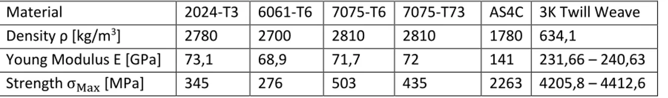
Because it won’t be exposed to any extreme structural nor aerodynamic forces, the main part will be to make the fuselage as light as possible while still able to hold its components and cargo. The two competitors are Aluminum alloys and Carbon Fiber. 2024-T3 is widely used in aircraft parts which are exposed to high tension, like wing and fuselage structures, but likewise is inferior to the carbon fibers in terms of all interesting material data. This can be summarized in the table below.
Material 2024-T3 6061-T6 7075-T6 7075-T73 AS4C 3K Twill Weave
Density ρ [kg/m3] 2780 2700 2810 2810 1780 634,1
Young Modulus E [GPa] 73,1 68,9 71,7 72 141 231,66 – 240,63
Strength σMax [MPa] 345 276 503 435 2263 4205,8 – 4412,6
Table 4. Properties of different material.
There are two extra things to take into consideration in this case though.
• One thing is the risk of more complex structures for carbon fiber because it’s not just to weld the components together like there would be if using any aluminum alloy. There exists however, gussets which is used to reinforce carbon tube structures.
• The other thing is the element of repair. Aluminum components may be heavier and have less shear strength than a similar component made of carbon fiber, but if an aluminum component break, it’s significantly easier to replace it than with carbon fiber. But because the fuselage isn’t made for taking huge amounts of stress, resulting in a structural failure, that shouldn’t be a significant problem anyways.
With this in mind, a fuselage made of carbon tubes is definitely worth to take into consideration. Several companies manufacture carbon fiber trusses able to withstand the forces that can act on the fuselage. After some searching, the prime company seems to be Dragonplate, which provides a good material specification as well as CAD files for every part they manufacture. Therefore, the UAV will be modeled using these parts provided by Dragonplate [46] [47].
Earlier models of the front of the fuselage have just assumed a rectangular intersected area. That is a catastrophic aerodynamic design, resulting in loads of unnecessary drag. A simple solution is to make the intersected area into a rectangular pyramid with a semi-sharp top at the nose. That cuts drag done by the body by at least 40%, and potentially by up to 93% [48]. To maintain the element of symmetry, the back of the UAV will be identical.
The length of the UAV poses a problem though with the mounting of the engines along with the wing. The rotors will have a radius of 34”, or 836,6 millimeters converted. Adding the wing which has a chord length of 800 millimeters gives a minimum length of the body, not including the nose and tail of 2527 millimeters, rounded to 2600 for safety margins. This makes it possible to tilt the wing without interfering with the engines. Making the nose as long as its height adds an extra 820
26
millimeters to the length, making it 3420 millimeters. The new and final dimensions of the UAV to becomes 3420 ∗ 800 ∗ 410mm
By using the old structure of the body, additional diagonal rods will be used around the batteries for extra strength. By using Pythagoras’ theorem, these are determined to have a length of 811,2 millimeters. Four of these rods will be used, and combining with the extra length the total length from the rods, the total length of rods combined will be 28451 millimeters.
To calculate what dimensions is needed to switch from the aluminum to carbon fiber, the easiest way will be to look at equation (18) or (20). This is because the force and length of the structure is the same for both material, their values aren’t interesting for now. Because the aim is to make the carbon fiber structure bend at the maximum as much as the aluminum one, preferably even less, this makes the only variables the area moment of inertia I and the Young’s modulus E. This means that the calculation will look as follows:
(IE)Aluminum≤ (IE)Carbon fiber
IAluminum= 6,84 ∗ 10−9 with an outer diameter of 20 mm and a thickness of 8mm and
• EAluminum= 73,1 GPa • ECarbon fiber= 234,4 GPa
This gives that the minimum area moment of inertia for a rod made from carbon fiber must at least be I = 2,13 ∗ 10−9 m4.
By looking at the material specifications, the carbon fiber square tubes must be at least 1′′∗ 2′′ with a thickness of 0,05’’ to meet the requirement. Its weight is 0,14 lb/ft or 0,21 kg/m converted. The total length of the carbon tubes is 28,5 m, giving the structure a weight of 5,985 kilograms.
4.3.3 Skin
Because the skin will experience minimal forces (due to the skeleton absorbing most of it), the focus isn’t on the strength of it, but rather on the weight. This makes carbon fiber prepreg a preferable material to use. Due to carbon fiber also having corrosion resistance, it’s perfect to use as skin for the UAV which run the risk to be in contact with water when it deploys the naiads. A thickness of the skin of the fuselage was proposed to 1,5 millimeters. But because the skin will mainly be used as a cover, that thickness can be narrowed down to half of that, aimed at 0,75 millimeters [49]. Due to a
redesigned fuselage, it’s not as easy as just cut the weight in half, so a new calculation will have to be made. The areas needed to be covered is
• Four triangles from the front and back structure, making eight in total. • Both sides on the central fuselage.
• The bottom. • The top.
To start with the front and back structure. The bottom area is 410 x 800mm and the height in the center is 410mm. Using Pythagoras theorem, it’s concluded that two of the triangles will have a height of √2052+ 4102= 458,4 mm and the other two sides √4002+ 4102= 572,8 mm. This
gives that the two sides have the area 0,3667 m2 and 0,245 m2 respectively. Four of each gives a total
27
The center fuselage will have a length of 2600 mm, so the two sides with the height 410 mm will have an area of 2,132 m2 and the other two sides, 4,16 m2. This gives the total skin on the fuselage an
area of 8,702 m2. Using prepreg 3k Twill weave carbon with a thickness of 0,012” (0,3048 mm), a
total of three layers is needed to reach the aimed thickness at 0,75 mm. With a weight of 0,193 kg/m2 per layer, the total amount of prepreg would weigh 5,04 kilograms. This gives an additional
redundancy in the extra thickness [50].
The last thing to calculate is the area of the holder of the wing while at horizontal flight. It will have the form of a pyramid with the height similar to the distance between the lower and the middle chamber and an angle at the base of 12°. One side will be dented to allow for the lower camber to take its place. SolidWorks mass properties tool calculates the area to be 0,833 m2, giving the UAV an additional weight of 0,49 kilograms, making the total weight 5,53 kilograms.
4.3.4 Drag on the body
To calculate (17), the Mach number needs to be calculated as described. This is done where u is 38,87 m/s, and T is 281,66 K. This gives that R = 287 J/Kg, K and κ = 1,4, giving a Mach number of 0,116.
The Reynolds number is calculated using equation (8) and is for the fuselage, 6,92 ∗ 106. Now the skin friction drag coefficient for the fuselage can be calculated, being 0,00318.
The wetted area is the same as the total skin area calculated above and was 8,702 m2. S
fuselage is the
area of the UAV, which also is 8,702 m2, gives a c
D,0 of 0,00318 as well. This shows that a fuselage
has next to no existing induced drag as showed in equation (14).
This makes the new total coefficient of drag of the UAV to be 0,03838, giving it a new lift-to-drag ratio of 36,48, and a maximum range at 25534,14 meters, per glide. Keep in mind that these are still quite uncertain numbers. Suggestions to determine the total drag more precise will be covered in future work. However, even if the drag is doubled, the UAV will be able to reach its target range of 25 kilometers.
Calculations also shows that in the most optimal conditions of free fall; the UAV will achieve a maximal Mach number of 0.49. And since there is no way this aircraft will reach transonic speeds (M > 0.75), the Whitcomb area rule can be disregarded [51].
4.3.5 Stall speed
When everything is calculated, a both interesting and potentially vital piece of data to know is the minimum flying speed, that if the UAV drops lower than that, the wing can’t generate enough lift, and the aircraft stalls, falling uncontrollable to the ground. To calculate at what speed this occurs, equation (1) is rewritten as
vStall= √
2L ρscL
(27)
This gives the UAV a stall speed of 27,85 m/s or 100,25 km/h, which means that the aimed speed is 40% higher than the stall speed.
28
The positive thing with this being a VTOL aircraft, is if a stall would occur, it should just be a matter of starting the engines quickly and tilt the nose down to maximize the airflow over the wing to break out of the stall.
4.4 Rods to hold the motors
Because the motors will provide the UAV with the thrust required to perform its VTOL, the rods holding the motors will have to be strong enough to withstand the bending and the shear force that acts on it while in VTOL mode.
By just looking at the properties table, it’s clear that 7075-T6 and 7075-T73 are both inferior to the others, making them seemingly not worth considering right now, leaving 2024-T3 and 6061-T6. However, their strength is bigger by a considerable margin. Because the problem in earlier designs have been the structural strength, those alloys may be interesting to consider in the wing design later. But because the safety margin on the tension strength already is enough for the other material, where this thesis aims for the recommended safety margin of σ =σMax
1,5 , it makes the trade in weight
in comparison to their strength unnecessary to use for the rods [52] [53].
However, all the alloys are inferior to the both carbon fiber prepregs in both simplicity and properties. Here the 3K Twill Weave wins by a large margin, making it the go-to material for the applications which carbon fiber is useful for. All calculations will use the low numbers to ensure the strength.
The diameter of the rotors is chosen to be 68 inches. Converted to meter, that becomes
1,7272 meters, making it have a radius of 0,8636 m. This means that the rod must have an outer length of at least L = 0,9 meter to ensure that the rotor won’t hit the body of the UAV. However, earlier theses chose the outer length to be 1,1 meters. The total length of one rod will in that case be 1,1 meters on both sides plus the length of the fuselage which is 0,8 meters, which comes out to three meters per rod [54]
Having the length of the rod outside the fuselage, it’s possible to calculate the moment. For that, the force P felt from the thrust T is needed. It’s calculated using
P = T − mMotor∗ g (28)
T =mTotal∗ g ∗ 1,6
4 (29)
where mTotal= 495kg and mMotor= (9 + 2,95) kg for the motor itself and the Powerfin F blades,
making T = 1944,36 N and P = 1827,011 N.
By using the equation for the moment M = PL, gives M = 2009,7121 Nm.
When the material now is chosen, the density, Young modulus and strength also gets defined. This makes it possible to accurately calculate everything needed for the rod. Earlier theses concluded that the dimension for the rods would be an outer diameter D = 44,45 mm and an inner diameter d = 42,88 mm, so it’s a good starting point here too, but because the true minimum of the dimension needed on the rods is unknown, a dimension factor a will be used for these equations, making them look like this:
29 ZMax= ZMax0∗ a (31) Wb = Iy ZMax = Wb,0∗ a3 (32) σ = M Wb,0∗ a3 (33) • Iy is 2,567 ∗ 10−8 m4 • ZMax is 22,225mm • Wb is calculated below
By rewriting equation (32), the dimension factor is obtained as
a = ( M wB,0σ ) 1 3 (34) with the given values wB,0= 1,155123736 ∗ 10−6 and with the given M = 1644,3099 Nm and σ =
2803,9 MPa. Because the dimension factor is very sensitive to the slightest difference in a decimal, every decimal possible will be used to calculate it. Using the numbers above, a is calculated to be 0,853.
This means that the new rods will have a minimum outer diameter of 37,9 mm and an inner diameter of 36,7 mm, which gives it a minimum mass of 0,15 kg with the density provided. It’s new area moment of inertia Iy= 1,359 ∗ 10−8 m4
The displacement due to bending can be calculated using equation (18) but with the addition that the rods itself will bend naturally downwards, making it look like
w(L) =PL
3
3EI−
mRodgL3
8EI (35)
where mRod is the mass of the rod outside the fuselage, which comes out to 0,13 kilograms.
This comes out to 0,258 meters.
By deriving (19), the angle which a rod bends is calculated as: w′(L) = θ(L) =PL 2 2EI+ mRodgL2 6EI [rad] or ( PL2 2EI+ mRodgL2 6EI ) 180 π [°] (36)
which gives a bending angle of 0,351 rad or 20,1°
This may seem like it bends a lot. But by using a formula to see the effective upward facing thrust while at full bend which looks like
η =Tcos(θ)
T (37)
the effective up-facing thrust quota obtained is then 𝜂 = 0,939 (a reduction by just 6,1%) and it gives an effective up facing thrust of 1826 Newtons per motor. This is well above the absolute minimum of 1215 Newton thanks to the 1,6 times extra thrust the earlier thesis suggested.
30
4.5 Wing
The wing will have to be able to lift the whole UAV while gliding. It will be mounted on the top of the fuselage to ease the use of the tilt-wing design by using one solid structure instead of one wing on each side. By having the wing on the top, it also naturally evades as much debris whipped up from the motors as possible, potentially resulting in FOD. The structure of the wing will consist of
• Form-giving ribs and nose ribs.
• Longitudinal spars to pick up the bending forces. • Skin to help carry the load during the vertical flight. • Ailerons for maneuvering.
The ribs will take the form of the chosen airfoil which was RG15. It will mostly be used to keep the shape of the airfoil and strengthen the structure when going from vertical mode to horizontal. Because of its relative complex design, carbon fiber probably isn’t a practical solution. Instead, the initial material chosen will be 2024-T3 with the reservation of a change if a good alternative is found. The longitudinal spars will be divided into two separate models. One model will have a length of 10 meters and several of these will be put in the front through the ribs to give stability to the whole wingspan. The smaller ones are 4396 mm and two of those will be put at the back of the ribs to further strengthen them. One special rod will be put in the intersection between the ribs and aileron to make the ailerons having something to rotate around. Having shorter rods in the middle will make a trimmed area in the wing as wide as the fuselage. This is for making it possible to tilt the wing when going from VTOL to horizontal flight.
The skin will simply be made of a 1,5-mm thick carbon fiber based prepreg which then is applied to the ribs to form a smooth form of the wing. It will also act as a safety layer for the ribs and spars due to its corrosion resistance when potentially landing in wet areas.
To allow for a reliable source of maneuvering, each wing will have ailerons to aid its ability to move around in the roll-axis. This will be done simply by making a part of the trailing edge movable. Then it’s just a matter of putting an electrical motor for control.
4.5.1 Form-giving Ribs
The main purpose of the ribs is simply to keep the shape of the airfoil. When the wing twists during its flight, the ribs help to keep the skin in place. Because the skin is being made of a carbon fiber based prepreg, it’s very strong against bending. However, it’s not nearly as strong in torsion
4.5.2 Longitudinal Spars
The most vital structure on the wing has to be the spars which runs through the whole wingspan. They need to be strong enough to maintain a safe flight and at the same time weigh as little as possible. This will be done by using carbon fiber tubes, giving the best strength and design to the least weight. Because there’s a finite size the tubes can reach, it’s necessary to use more rods instead. To calculate the amount of spars needed, equation (32) is used together with equation (31) but with a small modification. Because the equation describes the area moment of inertia for one single hollow rod, an amount of rods N can be added, giving it the appearance
σmax =
M Wb
= M ∗ zmax
31
The moment here is different from (32) though. This moment is given by the lift force L one side of the wing experiences, which is equal to half of the weight of the UAV. Because the lift force isn’t a point-based force, the point which it acts can be normalized to the midpoint of the length of the wing 𝑙 which is outside the fuselage. This can be described as
M =L 2∗ l 2= L ∗ l 4 (39)
This gives a moment of 5590 Nm if the lift is 4861 N and the length is 4,6 meters.
𝜎𝑚𝑎𝑥 is taken from data sheets, and this thesis will use the data from Dragonplate, which is 640 ksi,
converted to 4412,6 MPa.
The dimensions needed for calculating the area moment of inertia Iy will be made using standard
dimensions and the data sheets from Dragonplate [55]. A good choice is their rod with the inner diameter d = 1,5" and a thickness of 0,04”. Converted so SI units, the outer diameter D is 40,132 mm and the inner diameter d, 38,1mm. With a weight of 0,164 kg/m, this gives the spars a weight of 0,7544 kilograms each and an Iy= 2,389515236 ∗ 10−8 m4.
With these inputs, the number of rods needed N comes out to be 1,06. This means that to ensure a structural stable wing, two of these rods needs to be used along the whole wing, which gives it a good safety margin too. This seems like the only realistic solution because by looking at Dragonplates rods which have an inner diameter of 1”, too many of these rods are needed to ensure the same stability, which would mean an increase in weight. And increasing the diameter further is not possible either due to the size of the airfoil. So, the spars will consist of three 1,5” inner diameter, 0,04” thick braided carbon fiber tubes for now.
Because both the lift and gravity act on the whole wing (with lift being the bigger one because the UAV don’t drop out of the air), a different type of equation has to be used, looking:
w(L) = 1 𝑁( qL4 8EI) where q = (P − mwing2 ∗ g) L (40)
Making the new equation look like
w(L) =1 N(
(P − mwing2 ∗ g) L3
8EI ) (41)
Where
• N is the amount of spars used • L is the length of the wing
• P is the weight of the UAV, and is halved because each side of the wing will lift an equal amount.