Application of IEEE 802.15.4 for home
network
Tobias Jonsson
Gabriel Acquaye
THESIS WORK 2008
Electrical Engineering
Tillämpning av IEEE 802.15.4 för
hemnätverk
Tobias Jonsson Gabriel Acquaye
This thesis work is performed at Jönköping Institute of Technology within the subject area electronics technology. The work is part of the university’s master’s degree. The authors are responsible for the given opinions, conclusions and results.
Supervisor: Youzhi Xu and Infospread AB Examiner: Youzhi Xu
Credit points: 30 points (D-level) Date: 2008-10-10
Abstract
Abstract
To implement a utility wireless sensor network, investigation of different wireless protocols has been performed. The protocols are Bluetooth, Wi-Fi, IEEE 802.15.4 and Zigbee. Consecutively literature studies have made it comprehensible to understand the function of the protocols that are suitable for development of wireless sensor networks. The importance of low cost, low power, reliable and high-quality properties for long distances are significant. IEEE 802.15.4 and Zigbee protocol are proper to implement as a wireless sensor network.
To reduce the human efforts in the configuration of the system, a comfortable method is implemented to facilitate the procedure. The applied method is based on an automatic configuration of the system. The configuration and the decision taking are implemented in the software. The system is designed to avoid interference to other wireless networks with the possibilities of reconfiguration. A uniform hardware and software design with separate functions of the system decided by a subsequent command for configuration is preferable. This imposes an advantage that increases the flexible potential of the system when a uniform solution is implemented.
To support the basic communication principles and control of the system, a buffer implementation has been introduced. The functionality of decision taking is distributed, configured by system commands from the host system. Detecting of system commands requires a properly operating buffer management. In consideration to the power consumption in reference to battery utilizations, the settings of RF-module and microcontroller have a powerful impact to reduce the power consumption. All possibilities of hibernates and avoidance of unnecessarily transmitting, should be deactivated to minimize the power consumption.
Sammanfattning
Sammanfattning
För att implementera ett användbart trådlöst sensornätverk, har en jämförelse mellan olika trådlösa nätverksprotokoll utförts. De trådlösa nätverks protokoll som har jämförts är Bluetooth, WiFi samt IEEE 802.15.14 och Zigbee. Efter åtskilliga veckor av litteraturstudier har stått till grund till valet av det trådlösa nätverksprotokoll som kommer att användas i projektet. Utvärderingen kommer att ta hänsyn till kostnad, strömförbrukning, tillförlitlighet, samt möjlighet till en lång räckvidd för det trådlösa nätverket. De trådlösa nätverksprotokoll som anses mest lämpliga för ändamålet är IEEE 802.15.4 och Zigbee.
För att undvika en allt för stor arbetsinsats har en lämplig metod för inställning av systemet införts. Detta har gjorts med hänsyn till användarvänligheten. Metoden är utvecklad med tanke på en automatiserad inställning av systemet där beslutfattandet och inställningarna är implementerade i mjukvaran. Systemet är designat för att undvika interferens med andra trådlösa nätverk av samma typ, samt möjligheten till ändringar av systemet. Med hänsyn till produktionen av systemet är en universell lösning att föredra där valet av funktion avgörs vid inställningen av systemet.
För att möjliggöra de elementära kommunikationsprinciperna och kontrollen av systemet, har en buffer implementerats i mjukvaran. Då beslutsfattandet är skilt från systemet, utförs inställningarna via systemkommandon från värdsystemet. En väl fungerande buffer är viktig för detektering av systemkommandon med tanke på en universell struktur för framtida vidareutveckling. Med hänsyn till strömförbrukningen vid användandet av batterier, är inställningarna hos radiomodulen samt mikrokontrollern av stor vikt vid reducering av strömförbrukningen. Alla möjligheter till viloläge i de aktiva komponenterna, samt undvikande av onödig sändning bör användas.
Acknowledgements
Acknowledgements
Great appreciation to Infospread AB for given the opportunity to perform a practical application solution for wireless sensor network. New and enlarged knowledge has been dedicated. Thanks to Edward Nordström for all his contribution during the thesis work. Great thanks to all the teachers at Jönköping University, especially Ragnar Nohre for the knowledge and the contribution they have applied to the thesis work. Thanks to Josef at (OEM electronics) for the support of XBee RF-modules.
Keywords
Keywords
• Sensor Network • XBee • IEEE 802.15.4 • Zigbee • Bluetooth • Wi-FiTable of Contents
Table of Contents
1 Introduction... 1 1.1 PROLOGUE...1 1.2 BACKGROUND...2 1.3 PROBLEM DESCRIPTION...31.3.1 Reason for own design...3
1.4 GOAL...4 1.5 PURPOSE/OBJECTIVES...4 1.6 LIMITATIONS...4 1.7 THESIS OUTLINE...4 2 Wireless technology ... 5 2.1 IEEE802.11(WI-FI) ...5 2.1.1 Introduction...5 2.1.2 Basic operation...6 2.1.3 Power management...6
2.1.4 Advantage and disadvantage...7
2.2 BLUETOOTH (IEEE802.15.1) ...8
2.2.1 Introduction...8
2.2.2 Basic operation...8
2.2.3 Power management...10
2.2.4 Advantage and disadvantage...10
2.3 IEEE802.15.4 AND ZIGBEE...10
2.3.1 PHY layer...10
2.3.2 The IEEE 802.15.4 MAC Layer ...11
2.3.3 Introduction...12
2.3.4 Basic operation...12
2.3.5 Power management...15
2.3.6 Advantage and disadvantage...15
2.4 COMPARISON AND CONCLUSION...15
3 Design options and decision ... 17
3.1 SYSTEM APPROACH...17 3.1.1 System architecture...17 3.1.2 System specification ...20 3.2 CHOICE OF COMPONENTS...22 3.2.1 Overview...22 3.2.2 Microcontroller ...22 3.2.3 RF-Module...24 3.2.4 Power consumption...26 3.2.5 Power supply...28 3.2.6 Interface circuits...30 3.2.7 Evaluation boards...30 3.3 HARDWARE DESIGN...32 3.3.1 CAD investigation ...32 3.3.2 Placement of components ...33
Table of Contents
3.4 SOFTWARE DESIGN...35
3.4.1 The causes of the choice of UART ...35
3.4.2 An investigation of buffer techniques...36
3.5 CREATING AND JOINING NETWORK WITH XBEE...39
3.5.1 Broadcast or unicast mode network...39
3.5.2 Auto association...40
3.5.3 Manual Host controlled association...41
4 Implementation ... 42 4.1 HARDWARE IMPLEMENTATION...42 4.1.1 Signal route ...42 4.1.2 Resistance net...43 4.1.3 Complete schematic ...44 4.1.4 PCB ...45 4.1.5 Hardware testing ...46 4.2 SOFTWARE IMPLEMENTATION...47 4.2.1 Program parts ...51
4.2.2 Control and detecting techniques...51
4.3 CREATING AND JOINING NETWORK...55
4.3.1 Broadcast network ...55
4.3.2 Auto association...56
4.3.3 Manual Host controlled association...58
4.3.4 Manual for the customer ...60
5 Results ... 61
5.1 TEST METHODS AND RESULTS...61
5.1.1 System test ...61
5.1.2 Test for auto association ...62
5.1.3 Test for manual association ...62
5.1.4 Increased tests and test results ...62
5.1.5 Hardware test ...63
5.2 FINAL PRODUCT...63
6 Conclusions and discussions ... 64
6.1 SUMMARY...64
6.2 FURTHER WORK...64
References... 65
Appendix ... 67
PRICE LIST FOR COMPONENTS...67
List of figures
List of figures
FIGURE 1: PRINCIPLE STRUCTURE OF THE SYSTEM 2
FIGURE 2: POWER HANDLING STATE IN INFRASTRUCTURED WI-FI DEVICE [9] 7
FIGURE 3: PICONET CONFIGURATION [2] 9
FIGURE 4: IEEE 802.15.4 PROTOCOL STACK [6] 13
FIGURE 5: IEEE 802.15.4 STAR AND PEER-TO-PEER [6] 14
FIGURE 6: A HIERARCHICAL COARSE OVERVIEW OF THE WHOLE SYSTEM. 18
FIGURE 7: A GATEWAY BOARD SPECIFIC DESIGNED FOR A SUFFICIENT FUNCTIONALITY 19
FIGURE 8: A SENSOR BOARD SPECIFIC DESIGNED FOR A SUFFICIENT FUNCTIONALITY 19
FIGURE 9: A COMMON UNIT BOARD WITH ALL FUNCTIONALITIES INCLUDED. 20
FIGURE 10: AVR MKII IN CIRCUIT PROGRAMMER AND DEBUGGER. 23
FIGURE 11: XBEE RF-MODULE 25
FIGURE 12: ALTERNATIVE MODULES [11] 25
FIGURE 13: ACTIVE SUPPLY CURRENT VS. VCC( INTERNAL RC OSCILLATOR, 8MHZ) [14] 27
FIGURE 14: IDLE SUPPLY CURRENT VS. VCC( INTERNAL RC OSCILLATOR, 8MHZ) [14] 27
FIGURE 15: POWER-DOWN SUPPLY CURRENT VS. VCC( WATCHDOG TIMER DISABLED) [14] 28
FIGURE 16: PICDEM Z DEVELOPMENT KIT [12] 30
FIGURE 17: MAXSTREAM DEVELOPMENT KIT 30
FIGURE 18: DESIGN WITH DC TO DC-CONVERTER 33
FIGURE 19: DESIGN WITHOUT DC TO DC-CONVERTER 34
FIGURE 20: A UART EMULATOR WITH A TRANSPARENT BEHAVIOUR. 35
FIGURE 21: EXAMPLE OF THE FUNCTIONALITY OF A CHARACTER BUFFER WITH ONE BYTE. 36
FIGURE 22: EXAMPLE OF THE FUNCTIONALITY OF A STRAIGHT BUFFER 37
FIGURE 23: EXAMPLE OF THE FUNCTIONALITY OF A SHIFT REGISTER 37
FIGURE 24: EXAMPLE OF A FUNCTIONALITY OF A SIMILAR FUNCTION AS A SHIFT REGISTER BY USING
POINTERS. 38
FIGURE 25: EXAMPLE FOR THE FUNCTIONALITY OF A CIRCULAR BUFFER 38
FIGURE 26: BROADCAST MODE BY SETTING THE DESTINATION ADDRESS LOW TO 0XFFFF, IN USE OF 16 BIT
NETWORK ADDRESSES. 39
FIGURE 27: UNICAST MODE BY SETTING THE DESTINATION ADDRESS LOW WITH THE SAME NUMBER AS THE
SOURCE NETWORK ADDRESS, IN USE OF 16 BIT NETWORK ADDRESSES. 40
FIGURE 28: HARDWARE BLOCK DIAGRAM 42
FIGURE 29: RESISTANT NET 43
FIGURE 30: SCHEMATIC DESIGN FOR SENSOR BOARD 44
FIGURE 31: PCB DESIGN FOR SENSOR BOARD 45
FIGURE 32: THE MAIN PROGRAMS WITH INCLUDED FUNCTION CALL FOR THE CONTROL PROGRAM WITH A
BUFFER HANDLER AND CONFIGURATION ROUTINES. 49
List of figures
FIGURE 34: A CIRCULAR BUFFER FOR EACH OF UART IMPLEMENTED AS A TWO DIMENSIONAL ARRAY. 52
FIGURE 35: A CIRCULAR BUFFER FOR EACH OF THE UART IMPLEMENTED AS TWO DIMENSIONAL ARRAYS
WITH UNLIMITED NUMBER OF BUFFERS. CONCERNED FOR GENERAL USAGE IN THE FUTURE. 52
FIGURE 36: A CIRCULAR BUFFER WITH ONLY CONTROL FUNCTION. 53
FIGURE 37: CIRCULAR BUFFER WITH CONTROL AND READ FUNCTIONS 54
FIGURE 38: BROADCAST MODE BY SETTING THE DESTINATION ADDRESS LOW TO 0XFFFF 55
FIGURE 39: AUTO ASSOCIATION COORDINATOR [10] 56
FIGURE 40: AUTO ASSOCIATION END DEVICE [10] 56
FIGURE 41: THE OUTCOME RESULT 63
List of Tables
List of tables
TABLE 1: SPECIFICATION OF IEEE 802.15.4 [6] 11
TABLE 2: COMPARISON OF DIFFERENT PROTOCOLS [13] 15
TABLE 3: COMPARISON BETWEEN TWO PROCESSORS WITH A DECISIVE IMPORTANCE OF THE NUMBER OF
UART’S 23
TABLE 4: CONSUMPTION WITH BATTERY SUPPLY 29
List of Abbreviations
List of Abbreviation
ACL Asynchronous Connection Less
AM Active Mode
AP Access Point
ATIM Announcement Traffic Indication Message CCA Clear Channel Assessment
CSMA/CA Carrier Sense Multiple Access with Collision Avoidance DCF Digitally Controlled Filter
DSSS Direct Sequence Spread Spectrum DV Digital Video or Voice
ED Energy Detection FFD Full Function Device
GFSK Gaussian Frequency Shift Keying ISM Industrial, Scientific and Medical ISO International Standards Organization LQI Link Quality Indicator
MAC Medium Access Control MC Microcontroller OSI Open System Interconnection PAN Personal Area Network PCB Printed Circuit Board
PC Personal Computer
PDA Personal Digital Access
PHY Physical Layer
PS Power Save
QOS Quality Of Service
RF Radio Frequency
RX Receiver RFD Reduce Function Device
SB Sensor Board
SCO Synchronous Connection Oriented SPI Serial Peripheral Interface
TDD Time Division Duplex
TDMA Time Domain Multiple Access TX Transmission
Introduction
1 Introduction
1.1 Prologue
Applications of wireless sensor network has increased tremendously for the past years and still rising. The focus on sensor networks for home application has a main topic of low power consumption and efficient implementation of hardware and software for various applications. Research on different wireless protocols has also been applied. Applications as 802.11 Wireless Local Area Network (WLAN) are inappropriate with a redundant data rate and high power consumption. Bluetooth protocol was primarily introduced 1994 for a low data rate for compensation of cables for computers and mobile devices. The disadvantage of Bluetooth protocol is the limitation of number of nodes that can be connected simultaneously (1 master & 7 slaves) and the high level of power consumption. A new implementation of wireless sensor network IEEE 802.15.4 and Zigbee introduced in 2000 with a main topic of low data rate control and sensor applications in wireless networks. Zigbee is predicated on IEEE 802.15.4 technological standard for low data rate in the Industrial, Scientific and Medical (ISM) frequency band. Low data rate provided by IEEE 802.15.4, allow communication among devices with consideration to very low power consumption in use of battery supply. IEEE 802.15.4 devices are appropriate for home environment with a main topic of a low cost and low data rate [1], [2], [4].
Introduction
1.2 Background
Infospread AB is a company with a corporate enterprise of mobile phone applications for public transports. The proposal of the project is to implement monitoring of water consumption with the help of wireless sensor network. The demands for the project are low cost maintenance and application handiness.
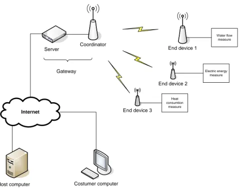
An important requirement for the wireless network is the plug & play functionality. XBee is the RF-module which provides the wireless communication and collection of information from the sensor nodes, for supervising of the water fluid, electricity or temperature, see figure 1. The server transmits further the information from the customer to the host system through internet connection.
Introduction
Research of different protocols within WSN is compulsory to fulfil the demands, since a lot of wireless protocol exists in the market. To avoid an expansion of the thesis work with unessential information, a decision was taken at an early stage to focus on three particular wireless protocols, relevant for development of the system. The conceivable protocols are IEEE 802.15.4/Zigbee, Bluetooth and Wi-Fi.
1.3 Problem description
1. Application of wireless communication from a sensor node to a coordinator based on IEEE 802.15.4 protocol further to internet by a server.
2. Avoiding of interference to adjacently IEEE 802.15.4 networks.
3. Essential hardware for power supply and communication for a desired function.
1.3.1 Reason for own design
Due to the absence of an evaluation board with an associative microcontroller connected to the IEEE 802.15.4 RF-module, a stand-alone microcontroller is required to be attached. Two particular evaluation boards are suitable for the thesis work. The two conceivable manufacturers of IEEE 802.15.4 RF-modules are Microchip and Maxstream, with differences of functionality. The RF-modules incorporated to the evaluation board consist of an integrated antenna which provides the license free frequency at 2.4GHz. The advantage in use of Microchip is that all essential hardware is enclosed, to facilitate the development. An application using Maxstream IEEE 802.15.4 RF-module requires a microcontroller. The choice of IEEE 802.15.4 RF-module from Maxstream was based on the delivery time, since the Microchip evaluation board would have taking two months, in contrast to two weeks delivery time for Maxstream RF-module.
Introduction
1.4 Goal
The main goal is to implement a low cost WSN with uncomplicated maintenance and application handiness solution. Avoidance of interference to adjacent wireless networks and possibilities for reconfiguration of the system are to be concerned.
1.5 Purpose/Objectives
The main purpose of the thesis work is to implement a Wireless Sensor Network with a main topic of private households. The project takes into considerations to avoidance of high costs.
The assignment is introduced with preliminary investigations of different wireless protocols and design options for the hardware and software.
1.6 Limitations
Due to the limited economic resources to apply a true experiment, a replacement of a switch or function generator, with a creation of an artificial pulse is directly connected into the external interrupt pin on the microcontroller to behave as pulse generator.
1.7 Thesis outline
The thesis is divided into 6 chapters. Chapter one gives a brief introduction of the thesis work and briefly explains Zigbee and IEEE 802.15.4 protocol. It also explains the problem that has to be solved and the goals of the thesis. Chapter two gives an introduction to wireless technology and the pre-studies performed to compare different protocols. Chapter three describes the primarily investigations. Chapter four describing the actual implementation part divided into two main subjects, hardware and software. Chapter five describes the result obtained for the thesis. Chapter six dispute the problems and further improvements.
Wireless Technology
2 Wireless technology
Before starting the design of the system that will be developed it is important to describe some of the technology that is involved in this project. It is important to mention about different wireless sensor networks (WSN) and some existing protocols.
Wireless sensor networks have very small and efficient power consumption nodes that transmit information from the environment. The information is sensed and sent wireless through the network to finally arrive to a management center where all the information is displayed. The information is then analyzed and appropriate decision would be taken to decide what needs to be done. Wireless Sensor Network (WSN) can be used for example in monitoring temperature, pressure, moisture, pollution, sound, vibration, and many other variables that need to be known. An important aspect of a WSN is the power management and the network which needs an appropriate protocol in order to take care of the energy consumption. This point is very important because a sensor network normally has a battery as a source of energy and needs to last as long as possible [1].
2.1 IEEE 802.11(Wi-Fi)
2.1.1 Introduction
The fast growing of wireless communication has contributed to less usage of cables. The devices that are suitable for this technology are many and some of the examples are mobile phone, personal computer and personal digital assistant (PDA) that needs to interact in order to share documents. These documents can come from several places such as email, information displays for customers in a shop or driver who wants to get access to map and tourist information while driving on the motor way. All this conveniences has been developed through the technological point of view [9].
Wireless Technology
2.1.2 Basic operation
Powered Wi-Fi station starts by scanning accessible channels to detect active networks in areas where beacons are located for transmitting. A network is then selected which will be in ad hoc mode. After this section it verifies itself with the access point (AP) and joins it. Several qualities of service (QoS) degrees are available in Wi-Fi network. Even though a station is already a part of a network it still tries to detect new networks and the reason for such behaviour depends on the willing to associate with the strongest signal and if this occurs the current network disconnects itself and joins the new network. This character is called roaming where networks share a common distribution system. Power in Wi-Fi stations can be saved by setting a station in to sleep mode.
2.1.3 Power management
The design of Wi-Fi connection is constructed mainly for long range communication, which then leads to higher absorbing of current. The absorbing range for Wi-Fi devices is around 100-350 Am. Wi-Fi devices can be at two different state and those are awake or doze. When a station is located in doze state it cannot transmit or receive. The power consumption is then reduced at this state. The power management is handled by two modes in Wi-Fi devices and these are active mode (AM) and power save (PS) mode. PS mode is handled in different ways depending on the type of topology the network is based on. A description of how the station behaves depending on which topology is used follows according to the article Bluetooth and Wi-Fi Wireless Protocols: A Survey and
Comparison:
Infrastructured Network- A station in AM which wants to pass in PS must signal the AP by using the power management bit in the header of its packets. The AP stores all the traffic addressed to stations that are in PS mode; when transmitting the periodic beacon, the AP sends the list of stations in PS mode and whether it has traffic queued for them at regular and configurable time intervals, the stations in PS switch to AM in order to receive the beacon. If there is traffic addressed to them, the stations can receive it and then return to PS.
Ad Hoc Network- Stations can use the PS mode, but the task of storing the traffic addressed to them is distributed among all the active stations since no AP exists. All stations in PS mode switch to awake state in a temporal window (ATIM window) during which the stations that have traffic stored for others send special frames (ATIM frames). If a station receives an ATIM frame addressed to it, it remains in awake state in order to receive its traffic; otherwise, the station returns to PS mode until the next ATIM window is started.
Note that:
“• Due to the absence of a reference station such as the AP, the instantaneous state of a station (awake or doze) can only be estimated by all other stations of the ad hoc network (e.g., according to the history of past transmissions). In this
Wireless Technology
topology, the standard does not specify any methodology for estimating the power state of the stations.
• The transmission and reception of the ATIM frames during the ATIM window occur according to DCF rules, i.e. according to the CSMA/CA access method. It means that a station could receive an ATIM frame addressed to itself, wait for the data, and yet not receive them because of congestion on the shared channel. In conclusion, the Wi-Fi standard specifies only one low-power state, the Doze state. Figure 2 below shows an illustration of what has been discussed above” [9].
Figure 2: Power handling state in Infrastructured Wi-Fi device [9]
2.1.4 Advantage and disadvantage
Wireless techniques provide many advantages, but leads to some disadvantage as well. The disadvantage of Wi-Fi network is the power consumption that is required before a transmission can be approved compares to Bluetooth which is extremely low in short ranges. But on the other hand Wi-Fi is more convenient when transmission of data is required for long range and power consumption is not an issue.
Wireless Technology
2.2 Bluetooth (IEEE 802.15.1)
2.2.1 Introduction
Bluetooth is wireless technology where devices can communicate with each other within a short range. The specification is based upon the Radio Frequency (RF) operating in the unlicensed 2.4GHz ISM (Industrial, Scientific and Medical) band and the technique is based on low-cost, short-range radio link which makes it easy to ad-hoc connections for stationary and mobile communication environments. The specification is available for areas such as short-range, point-to-multipoint, voice and data transfer [2].
2.2.2 Basic operation
The functionality of Bluetooth communication is based on frequency hopping system with a nominal hopping rate of 1600 hops per second. The hops are divided into time slots, each 625 µsec long. The reason why Bluetooth uses frequency hopping is for low interference and fading. For full duplex transmission it uses TDD (Time Division Duplex) scheme and transmits by using GFSK (Gaussian Frequency Shift Keying) modulation.
Bluetooth protocol uses a mixture of circuit and packet switching. The protocol stack can use an asynchronous connection–less (ACL) link for data and up to three simultaneous synchronous connection-oriented (SCO) links for voice or a mixture of asynchronous voice (DV packet type).
When two or more application are connected to the same channel in Bluetooth network it creates a piconet, which contains a master device and up to seven active slave devices. Interference becomes greater in Bluetooth communication when the amount of piconet increases. This courses a packet collision that needs retransmission. The reason to this is because of the randomly frequency hopping system provided by the Bluetooth communication amongst a total of 79 frequencies. A Bluetooth device can function in either master or slave mode. The maximum number of device which a piconet can contain is eight devices seven active slaves plus one master see figure 3, which is the simplest configuration of a Bluetooth network. [2].
Wireless Technology
Figure 3: Piconet Configuration [2]
How device get discovered in Bluetooth environment, well to be able to communicate among Bluetooth devices some kind of function for device discovery has to be implemented before any communication can occur for packets to transmit on the wireless link between master and slave devices and vice-versa. The function for device discovery contains inquiry and paging. So what is the meaning of inquiry then, well it purpose is to help find the destination address for devices with unknown source. The inquiry function can also be used to detect which other Bluetooth devices are within the range. Under an inquiring sub state the detecting device gathers the Bluetooth devices addresses and clocks of all units that respond to the inquiry message. It can then, if desired, make a connection to any one of them by means of the page procedure, where the paged device is contacted directly and invited to join a piconet [2].
Wireless Technology
2.2.3 Power management
Power management is crucial aspect when it comes to wireless communication since it affects the battery lifetime. Conserving battery energy in mobile application is a hard challenge since consideration has to be taken in the entire protocol stack layers. The design of Bluetooth devices should be constructed in such way that it won’t be a burden on the battery lifetime. To avoid high power consumption in Bluetooth radio different levels of power conserving mode are included in the constructions and some of them are sniff, hold and park. Some other aspects that need to be considered too are base band mode and adaptive transmission power. The absorbing range for Bluetooth devices is around 1-35 Am.
2.2.4 Advantage and disadvantage
The main disadvantage with Bluetooth is the limitation of how far it can reach considering the range between devices communicating with each other. Another aspect that is also disadvantage for Bluetooth technology is the number of devices that can be connected simultaneously is only 7 devices. Now the positive side of Bluetooth is the power consumption since it consume very little power while active it give a beneficial of long time battery life compare to Wi-Fi which only last for couple of hours.
2.3 IEEE 802.15.4 and ZigBee
2.3.1 PHY layer
The physical layer main purpose is to control the radio of the device to evaluate the energy detection (ED) inside the channel and thereby impose Clear Channel Assessment (CCA) for Carrier Sense Multiple Access with Collision Avoidance (CSMA/CA). This control has to be introduced to avoid failure in transmission of data within a channel. What consumes most power in devices containing the PHY layer is idle listening. The ongoing consumption can be reduced by setting the Radio Frequency (RF) transceiver into sleep mode for a certain time and after that back to active mode. Three frequency bands is available in IEEE 802.15.4 with a total number of 27 channels, where 16 is applied to the 2.4 GHz, 10 for 915 MHz and finally 1 for 868 MHz. Devices that are constructed with IEEE 802.15.4 protocol stack implemented in it uses Direct Sequence Spread Spectrum (DSSS) to raise the bandwidth of the transmitted signal for a reliable communication. The physical specifications are given in the table 1 below [6].
Wireless Technology
Spreading parameters Data parameters PHY
(MHz) Frequency band MHz Chip Rate
K chips/s Modulation Bit kb/s Rate Symbol Rate K symbol/s Symbol
868 868-868.6 300 BPSK 20 20 Binary
915 902-928 600 BPSK 40 40 Binary
2450 2400-2483.5 2000 O-QPSK 250 65 Orthogonal 16-ary
Table 1: Specification of IEEE 802.15.4 [6]
2.3.2 The IEEE 802.15.4 MAC Layer
Applications for IEEE 802.15.4 wireless sensor networks are target for home automation, home networking, PC peripherals, home security and so on. Several of those application demands only low-to-medium bitrates around some few hundreds of kbps. The physical layer provides different bitrates depending on which frequency range is applied by the device. The frequency also decides how many channels are available within the frequency range. MAC protocol uses only one of these channels at a time. Since it is the MAC layer that is used to link communication between devices a general description of how device get associated and disassociated on the network follows below, which is according to the book: Protocols and Architectures for Wireless Sensor Networks.
• A Full Function Device (FFD) can operate in three different roles: it can be a PAN coordinator, a simple coordinator or a device
• A Reduced Function Device can operate only as a device
A device must be associated to a coordinator node (which must be a FFD) and communicate only with this way forming a star network. Coordinator can operate in peer-to-peer fashion and multiple coordinators can form Personal Area Network (PAN). The PAN is identified by a 16-bit PAN Identifier and one of its coordinators is designed as a PAN coordinator.
A coordinator handles among others the following task:
• It manages a list of associated devices. Devices are required to explicitly associate and disassociate with a coordinator using certain signalling packets. • It allocates short addresses to it devices. All IEEE 802.15.4 nodes have a 64-bit
device address. When a device associates with a coordinator, it may request assignment of a 16-bit short address to be subsequently in all communications between device and coordinator. The assigned address is included in the association response packet issued by the coordinator.
Wireless Technology
• In the beaconed mode of IEEE 802.15.4, it transmits regularly frame beacon packets announcing the PAN identifier, a list of outstanding frames, and other parameters. Furthermore, the coordinator can accept and process requests to reserve fixed time slots to nodes and the allocation are indicated in the beacon. • It exchanges data packets with devices and with peer coordinators [7].
2.3.3 Introduction
IEEE 802.15.4 or Zigbee is a wireless personal area network (PAN) which can be used in several areas. Some basic areas where it can be utilize are building automation, control devices, personal healthcare, PC peripherals and consumer electronics.
The main technology used to develop the wireless network for IEEE 802.15.4 and Zigbee is based on the same layers which are physical (PHY) and medium access control (MAC). The huge different between IEEE 802.15.4 and Zigbee is the ability of which kind of topology can be provided by the network. More over the security level in Zigbee is higher compare to IEEE 802.15.4. The IEEE 802.15.4 can provide point-to-point and point-to-multipoint topology, called star topology, while Zigbee can be used for the one’s mentioned above plus cluster tree and mesh topology. To achieve the functionalities which Zigbee can provide two more layers from the Open System Interconnection (OSI) is added and those are Network and Application layers. [1], [4].
2.3.4 Basic operation
The main focus of IEEE 802.15.4 protocol is it ability to deliver low power consumption and low-rate wireless communication devices. The following numbers of channels can be used in IEEE 802.15.4, which is 16 channels for ISM 2.4GHz, 10 channels for ISM 900 MHz and 1 channel for 868 MHz. The PHY-layer used in IEEE 802.15.4 provides Link Quality Indicator (LQI) for the communication that occur between transmitter and receiver in order to maintain good quality of signals transmitted between nodes. The MAC layer which is utilized in IEEE 802.15.4 for communication is based on Carrier Sense Multiple Access with Collision Avoidance (CSMA/CA) mechanism to get admission of the channels. Devices that are supported by IEEE 802.15.4 are Full Function Device (FFD) and Reduced Function Device (RFD). A device which is constructed as FFD can be used for both FFD and RFD in communication. FFD can also be set as PAN Coordinator, Router or End Device, while RFD is only suitable as End Device. Communication for RFD can only occur with FFD. An overview of how the protocol stack is defined for IEEE 802.15.4 is shown in figure 4.
Wireless Technology
Figure 4: IEEE 802.15.4 protocol stack [6]
There are two types of communication mode process available in IEEE 802.15.4 for avoiding interference in an environment where several system are running on the same frequency band. The modes which help to reduce the disturbance are beacon mode and non-beacon mode. The article Development of Ubiquitous Sensor
Network by Shigeru Fukunaga, Tadamichi Tagawa, Kiyoshi Fukui, Koichi Tanimoto and Hideaki Kanno describes how the different modes of beacon affect the
communication which follows:
“The beacon mode is used with Star-type networks that are configured with the network management node, referred to also as the “PAN coordinator”, at the core. The PAN coordinator sends off a beacon signal at fixed intervals, while other nodes synchronize with this beacon signal and perform communications during allotted periods. Since only the node that has been singularly assigned by the coordinator gains exclusive use of the channel, it becomes possible to conduct communications in which no collisions can occur. This mode, therefore, is used for communications requiring low delay levels.
The non-beacon mode, on the other hand, is a mode wherein the channel is accessed constantly with the CSMA-CA. When this mode is used in a mesh link, with which direct communications are conducted with peripheral nodes, each node can directly communicate with any other mode at any time, while each node can also be ready to receive data addressed to that node, at all times. This need for each node to constantly remain in a reception standby condition makes it impossible to conserve energy by conducting intermittent operations as in the case of the beacon mode”.
Wireless Technology
Energy conserving process is available in End Devices by introducing non-beacon mode in a Star-link situation where the master unit is set as constant reception in a standby condition. To achieve this behaviour the End Devices are set to interrupt periodically in suspended or standby condition. Introducing this function in the End Device will enable request to receive data is periodically sent to master unit from End Devices. This is the main flow pattern for data in sensor networks. The figure below is an example of two types of topology that is available in IEEE 802.15.4 [1], [5].
Wireless Technology
2.3.5 Power management
The main focus for power management for IEEE 802.15.4 is based on low cost, low consumption and low data rate. Implying all this aspect together gives us a significant protocol that consumes extremely low power.
2.3.6 Advantage and disadvantage
There are several reasons for why it is convenient to impose IEEE 802.15.4 protocol for wireless sensor network in areas where the need for transmission of data-rate is low and requirement of energy conserving is a huge concern. First of all it provide long battery life, due to it low transmission speed which is about 250kbs/s. Secondly it is easy to imply in systems and quite simple to use for development of networks. IEEE 802.15.4 sensor networks can handle up to 64000 devices simultaneously compare to Bluetooth which can only support 7 devices at the same time. The only disadvantage that is provided by IEEE 802.15.4 protocol is it data transfer ability.
2.4 Comparison and conclusion
Some aspects that state the differences in the wireless sensor networks discussed above are given in this table. Note that all of the facts in the table are not considered it’s rather the basic part of the network that is interesting.
Feature (s) IEEE 802.11b Bluetooth Zigbee (IEEE 802.15.4)
Battery Life Hours Days Years
Complexity Very Complex Complex Simple
Nodes/Master 32 7 64000 Latency Enumeration up to 3 seconds Enumeration up to 10 seconds Enumeration Up to 30 milliseconds Range 100m-1000m 10m 70m-300m (ETSI), 1600m (FCC)
Extendability Roaming possible No Yes
RF Data Rate 11Mbp 1Mbps 250Kbps
Security Authentication Service set
ID(SSIS) 64-bit, 128-bit
128-bit AES and Application Layer user defined
Wireless Technology
After learning how the differences in the protocols affect the power consumption, number of nodes or master which can be offered, how far they can reach concerning communication and RF data rate that is available for the protocols, it has become clear to understand which kind of protocol is reasonable to implement. Depending on which area the network is meant to be applied several facts are to be considered. Some of the facts are transmission rate, battery lifetime and security level and so on.
Decision
3 Design options and decision
3.1 System approach
Before taken a decision for how the entire system would function when completed they are some main aspects that should be in consideration and these are described in details before approaching implementation.
3.1.1 System architecture
The development of a wireless distributed system is depended of used components and a transferring protocol. Introducing an already working RF- module leads to that the developer doesn’t need to care about the protocol itself. A use of a UART emulator as communication link, interprets as a wire. Depends on the task of the system and the most cost effective solution decides the distribution of the hardware and software. By using cheap components, a cost effective and uniform product can be manufactured with all parts in the system as similar as possible. To avoid producing a specific PCB for every unit an effective solution is imposed by constructing the hardware as similar as possible for all units regardless the function. The same applies to the software which means all the program parts are united as one program to facilitate the programming of the processors during the production. The sensor board as an end device in the wireless network use only specific components for its task. The same applies to the gateway as coordinator. The end device sensor board needs here an input to the processor through a signal level adapter such as resistance net. In consideration to the software implementation, the software part which only manages the running program and the start up configuration specific for the sensor board is required. The gateway node as a coordinator requires some communication to a server. The use of a common standard such as RS232 requires an interface component connected to a D-sub socket. In this case an external web server is used. By using an embedded web server an RS232 signal level transformer as interface component is not required. A normal digital signal level of 3.3 volt is sufficient by the communication. An embedded web server using an Ethernet socket (RJ45) placed on the PCB is sufficient by connecting it to internet through LAN. If the customer is using a wireless LAN at home, the 802.15.4 wireless network is not to be required. Using a wireless LAN should simplify the system when a gateway doesn’t require for the wireless solution. In case of the use of wireless LAN, the sensor board sending the information instant to the modem and further to the host computer by internet. A solution by using wireless LAN can be suitable in use of only a few sensor boards. For further development of an implementation to use the Zigbee protocol has an advantage considering to the property of a mesh network. The advantage to use a mesh network is the distance between the end device and coordinator with routers, which is utilized for large buildings in block of flats. For small buildings a star topology of wireless network should be enough. A more probable cost effective solution should be to use the Zigbee protocol as a wireless mesh network
Decision
distributed in a housing area. In this case it is sufficient to install the coordinator and web server to a terminal block in a phone station or phone cabinet near the housing area. Introducing a solution to use a web server for every household facilitates for the host computers to identify the source for received data associated to the IP number for the customer. By using a Zigbee wireless mesh network, the identification of the customer for the sensor boards needs to be set.
Coordinator End device 1 End device 2 End device 3 Costumer computer Host computer Water flow measure Electric energy measure Heat consumtion measure Internet Server Gateway
Figure 6: A hierarchical coarse overview of the whole system.
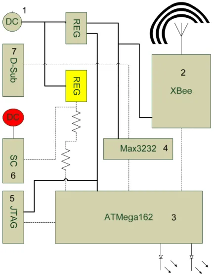
For simplicity both coordinator and end device are designed with similar architecture see figure 7, 8 and 9 below. The reason why the product is constructed this way depends on the configuration procedure implemented in the microcontroller. The configure procedure in the microcontroller decides if the function of the unit should coordinator or an end device. A possible solution for such behaviour is achieved by sensing incoming data and through that a decision can then be taken to set the unit for desired performance. In addition to the end device, when powered on and no response from a host is given, the unit automatically sets to an end device. All mentioned solutions are not planned to be implemented. The thought is to demonstrate an application of the solution by presenting the decision taking to a host computer.
Decision
Figure 7: A gateway board specific designed for a sufficient functionality
Decision SC JTAG D-Sub REG REG
Figure 9: A common unit board with all functionalities included.
3.1.2 System specification
Probable constraints from the customer as a normal modern human is to avoid a lot of advanced technical attempt to setup a new system, which they have bought to make their life easier and get control of their consumption of energy, water and electricity. The market for energy and consumptions resources force today’s people to have an overview of their consumptions for saving money. A way to get an overview of consumption is to use internet, which handles data and serve the information which helps to take a decision on how to change habits to reduce one’s consumption. Another application is to discover water leaking in houses by fast growing water consumption. The attempt is to design a well functioning network for the customer without knowledge in PC computers or being familiar with difficult technical instructions. The specifications for the project also include an easy handling for the company which is provided and support the system for the customer. The best optimized solution is to implement a total automatically system without manual settings before the product sends to last destination, the customer. Consider to the choice of wireless platform the best solution is to make a cost optimized embedded system without PC software, instead a small
Decision
embedded microprocessor is implemented which in turn is connected to the RF-module. The RF-module and processor are booth dependent of power supply and interface circuits to function and communicate with the surrounding components, connected on the PCB-board. In an early phase of the project it was decided to make an efficient solution in consideration of the hardware and the most convenient solution is to make a product without large effort for the customer and the producer. In respect to the customers the constrain is to develop a well functioning wireless network that is convenient without any technical requirement. The task includes two main functions both start up configurations for the wireless network and a decision taking program part. Consider to the simplicity for the customer as very ignorant, the system should work automatically as much as possible. How to configure the system depends on the number of sensor boards and one of the techniques for detecting is, to separate the sensor boards from each other. The reliability of the functions depends on how the configuration of the system is done. The most reliable way to deliver information for the wireless network is that all nodes in the wireless network should belong to the same network. The decision of which function the undefined unit is allotted need control from outside. The most reliable way is to make all decision from a host computer. Another simple and elegant solution is to detect the first incoming information from a sensor as a decision taking to be an end device. In case of only one solution of sensor, the undefined unit becomes an end device with a predefined program in lack of received commands during a time delay. In remind of an influence from adjacent similar wireless network the sensor board need to know which wireless network it belongs to. The used wireless 802.15.4 radio module XBee has an embedded function to connect to the nearest coordinator by measuring the strength field. To increase the reliability of the coordinator it has the possibilities to lock and unlock the network to control if an end device is allowed to join the network. To control the lock and unlock of the network is performed through the host computer. A suggestion is to receive an unlock command with a following implemented self locking after joining to the network. In knowledge to the functionality of the XBee module it is supposed that end device is joining the nearest network, consider to the strength of the field.
Decision
3.2 Choice of components
3.2.1 Overview
Before a decision can be taken for how a developed system should look like with thorough components a slight research on component has to be done since there are different components in the market with similar characters. In this case specific components are required for development of the system. Main component in the system is microcontroller (MC) which has been discussed earlier. Other components that are included is interface circuit for serial communication between hosts to MC and further on to RF-module, JTAG pins for programming the MC, DC-connector for input voltage, input connector for water meter, a reset button, two regulators and surrounding resistance and capacitance. RF-module used in this construction is XBee from Maxstream. Concerning the RF-module some discussion around it was done before a decision could be taken since many of them exists in the market and most of all a particular one that are with experience is Microchip which was supposed to be used at the beginning. Because of time constrains and long delivering time for the packet, another alternative had to be introduced which led to Maxstream module with similar functionality.
3.2.2 Microcontroller
The delivered RF-modules from the manufacture require a configuration to work as considered. For the laboratory work it is sufficient to use an evaluation board to configure the modules to create a well functioning wireless network. One of the constraints in this project is to implement an easy to use application for the customer. To achieve this, a microcontroller is required in the system for first time configuration. The basic functions for controlling the system is hardware UART, interrupt handling and basic calculations. An important function is the quantity of hardware UART’s. This project needs at least two UART ports to communicate with two or a number of devices. A common and suitable choice of processor is Atmega162 which has two UART ports. One of the two UART ports is used for communication, either between the microcontroller and the RF-module or between the microcontroller and external serial port. The external port is connected to an interface circuit which is transforming the signal level to a standard level for serial ports in computers. The advantage of using a hardware UART port is that, the handling of the UART protocol is embedded in the microcontroller, which only need one time configuration by setting baud rate, parity bits, and stop bits. Transmission through the UART is done by writing to a register which automatically handles the UART protocol. At the beginning of the project the processor AVR Atmega168 with only one UART was used. To communicate with the RF-module it is enough with one UART, but since simultaneous communication to external device is necessary a realization at early stage occurred, that two UART ports had a significant role.
Decision
The most common processors with embedded hardware have functions which are obvious such as external interrupts, timers, A/D converters. The main task in this project is to detect pulses from a water fluid sensor which requires some interrupt mechanism to capture the occasion when detecting an incoming pulse. From the beginning the idea was to use an earlier experienced processor, PIC-series from Microchip which has been used in other projects and laboratory experiments at the University. The investigation of choosing processor concluded with finding a C-compiler with no limit or high cost led to ATMEL processor. For the project it was sufficient to use a simple 8 bits microcontroller with embedded hardware. The conclusion to use a microcontroller from ATMEL was depended on the compiler AVR studio. The AVR studio is free to use and have no limits in differences to Microchips compiler. Table 3 shows the difference between the two microcontrollers that has been utilized during the project. Figure 10 is the programmer for the microcontroller.
Device SRAM SPI/JTAG USART Max I/O Pins
ATmega162 1024 Yes/Yes 2 35
ATmega168 1024 Yes/No 1 23
Table 3: Comparison between two processors with a decisive importance of the numberof UART’s
Decision
3.2.3 RF-Module
When the RF-modules leave the manufacturer it needs to be setup by the user for it to work as considered. For laboratory work it’s possible to use an evaluation board to setup the RF-modules to create a working PAN network. One of the constraints for the project is to construct an easy to use application for the customer. The basic functions for controlling the system is through hardware UART, interrupt handling and basic calculations. An important function is the quantity of hardware UART’s
The 802.15.4 RF-module XBee® is handling the protocol itself and the developer do not need to have knowledge for the protocol in detail to use it for an application to create a wireless network. The manufacturer attaches instructions for handling the setup of the RF-modules. In this RF-module commands can be sent in two different ways which are AT command and API-frame. AT command is an easy step to step method to send instruction to the RF-module while the system is in a command mode. To use API frames as method for handling the RF-module has it benefits at times. One of the benefits is that several instructions can be sent at the same time which gives it possibilities to send and receive data instructions and all commands simultaneously, without changing the RF-module command mode. The decision to use AT command as a method to handle the RF-module depends on the possibilities to use only a few instructions to build a high-quality working wireless network. The RF-modules are from the beginning manufactured set to connect with other RF-modules in a unicast mode without using a coordinator. To implement a wireless network with a coordinator and surrounding devices a PC-software is needed to setup every RF-module to their specific identity such as network address and other details to get the modules to communicate and work together in a network. Another constrain for the project is to setup the RF-modules and build a network without involvement of PC. It is possible to control and setup the RF-module automatically, but the instructions need to come from a host. Therefore the RF-module itself needs some control system to control it, which in this case is the microcontroller. Figure 11 shows the RF-module.
Decision
Figure 11: XBee RF-module
To be able to communicate with the PC as the host a need for implementation of serial port is compulsory. Such component is implemented on the sensor board. Other connections are possible such as USB, direct Local Area Network (LAN) or Wireless Area Network (WAN) with embedded serial communication. The alternative for LAN and WLAN module is shown in figure 12.
Figure 12: Alternative modules [11]
Decision
3.2.4 Power consumption
In use of battery based power supply, the power consumption has to be low as much as possible to avoid large efforts and increased costs for the customer. An advantage is the mobility of the devices. In case of the function as a sensor, the system only needs to be active during the measuring and communication handling. The RF-module and microcontroller has the possibilities to fall into sleep mode. The level of activity during sleep modes can be specified in the registers. The huge differences in level of sleep modes goes from deep sleep, power down, hibernate or to a more active mode doze. The deeper the sleep mode is the longer allotted wake up time it gets.
The RF-module XBee has three sleep modes. The most power saved mode is hibernate with a power consumption of 10µA and a wake up time of 13µs. A more active mode is to let the RF-module to doze, with a power consumption of 50µA and a wake up time of 2ms. This two sleep modes requires a wake up signal on a specified pin in the RF-module. The RF-module has also a cyclic sleep function with a predefined sleep and awaking period. This is useful in case of listening to received data from the network. In this case it is beneficial for water measuring sensors, where the expected detecting pulse from the water measure equipment can be as rare as one pulse per week. But the requirement for the system includes a transmission of still alive messages at least one time per day for support. The time constraints is low when measuring water consumption so the best choices should be to use the most power saved sleep mode such as hibernate [10].
ATMega162 with an active power consumption of 5mA when using 3V has a several sleep modes similar to the RF-module XBee. The power consumption is dependent of the clock speed and the supply voltage, see figure 13. The three useful sleep modes in ATMega162 is idle, power save and power down. In the idle mode the clock source in the processor and the hardware are prepared to work together for received signals. The power consumption in idle mode is 2mA with the use of 3V, see figure 14 for alternatives. In power down mode the CPU clock is suspended and also all hardware apart from a few special external interrupt pins. The power consumption for power down mode is less than 1µA with a utilization of 3V as power supply and disabled watchdog timer, see figure 15. The wake up time is increased in case of power down and idle mode are activated, but decreases the power consumption. The power save mode has properties that lie between power down and idle with the advantage of working hardware during the time CPU clock is suspended. In this case a use of water measuring with low time constraints allows the wake up time to be slow. The microcontroller is the first device that detects a received pulse which in turn can wake up the processor to implement interrupt routine. To minimize the power consumption, the main focus should be applied on the RF-module because of the large energy consumption during wireless communication [14].
Decision
Figure 13: Active Supply Current vs. Vcc( Internal RC Oscillator, 8MHz) [14]
Decision
Figure 15: Power-down Supply Current vs. Vcc( Watchdog Timer Disabled) [14]
3.2.5 Power supply
There has been some discussion about how to supply the system and some alternatives are proposed. The main alternative is to supply the system with one input voltage source which is about 30V. This voltage will then be regulated to 3.3V and 25V respectively by two regulators, type LM317T. The problem with this solution is that the regulator for 3.3V becomes overheated when operating, even if attached to heat sink and the reason why this situation occur depends on the power development over the regulator because of the huge voltage differences between input and output. To solve the upstanding problem another regulator should be introduced in this case a DC to DC-converter. Some detail information about it functionality follows:
DC to DC-converter is a circuit which converts a source of direct current (DC) from one voltage level to another. These DC to DC-converters convert one DC voltage to another by storing energy into a magnetic component (an inductor or a transformer) for a period of time (usually in the range 30 kHz to 5 MHz ). By adjusting the PWM Duty Cycle (the ratio of on/off time), the amount of power transferred can be controlled. Usually this is done to control the output voltage, though it could be done to control the input current, the output current or maintaining a constant power [4]. Introducing DC to DC-converter in the system is costly, but provides the best solution. This alternative will not be implemented in the project, since it is the company that decides the financial part.
Decision
The other solution which will be implemented in the project is to provide the system with two input source one for the involving components and the other one for the water meter. This prevents the overheating on the regulator since it is supplied with only 10V which regulates down to 3.3V. The water meter included in the system will be supplied with 25V and its output pulse scaled down to 3.3V through the resistance net. Power consumption is not an issue for this system since is not driving with battery.
Since the project is based on wireless sensor network it is desirable if no cables are included for instances powering the sensor board. The main issue with implementing battery is the level of power consumption of the XBee module while sending data. The value is about 50 mA and depending on which battery type is being used and the amount of ampere hour that can be delivered decides the life time. Concerning this fact an assumption for how long 9V battery with a value of 2000 mAH can last while supplying a sensor board with a power consumption of 50 mA. A calculation for the assumption is shown in table 4 depending on if the RF-module is sending all the time or sleeps after every pulse interval. current Device hour current of Amount hours in time Life =
Sending constant Sleeps after every pulse
Battery type 9 V 9 V
Amount of current hour 2000 mAH 2000 mAH
Device current 50 mA 50 mA
Number of pulse 1 pulse/H
Life time in hours 40 24*40 =960
Table 4: consumption with battery supply
Table 4 reveals the differences in available modes that can be achieved from the sensor board. In sleep mode after every pulse the amount of life time in hours has to be multiplied by 24 since current is only consumed when a pulse is sent every hour. Consumption current during sleep mode is negligible given that is less than 10 µA.
Decision
3.2.6 Interface circuits
The interface circuit main purpose is to transform signal levels to suitable signals adaptable for PC signals since it behaves as a host for the sensor board. The interface circuit which is suggested for implementation is Max3232 with an input voltage level from 3 V. The circuit is pin compatible with an RS232 standard interface for serial communication. The voltage level of RS232 corresponds to logical one and logical zero levels. Acceptable signal levels are ±3 to 15 V. The driver and receiver of RS232 should be able to endure indefinite short circuit to ground or voltage levels up to 25 V.
± ±
3.2.7 Evaluation boards
The RF-module implemented on the sensor board is called XBee constructed by the company Maxstream and before the decision was taken concerning to which module will be utilized on the sensor board a comparison with another RF-module was done. This RF-RF-module is from Microchip and the performance is similar to the XBee RF-module.
Figure 16: PICDEM Z development kit [12]
Decision
Figure 13 and 14 above reveals the differences between the development kits and some detail description follows. Microchip development kit is good for evaluating such project performed on this thesis, same applies to Maxstream development kit. The huge differentiation between them is the microcontroller mounted on the Microchip board compare to Maxstream where such does not exist. The microcontroller on Microchip evaluation kit can be modified as desired and data can then be transferred through the RF-module. To achieve this behaviour on Maxstream development kit an implementation of microcontroller is necessary. Below feature and content are list for comparison of the development kits.
Key features of the PICDEM Z Demonstration kit include:
• ZigBee software stack supporting RFD (Reduced Function Device), FFD
(Full Function Device) and Coordinator
• PIC18LF4620 MCU featuring nanoWatt Technology, 64 KB Flash memory and robust integrated peripherals
• Microchip MRF24J40 RF transceiver and antenna interface via daughter card for flexibility
• ZENA™ wireless network analyzer tool including software protocol stack configuration (DM183023)
• ICSP™ and MPLAB ICD 2 interface connector
• RS-232 interface
• 9V DC to 3.3V DC regulator
• Temperature sensor (Microchip TC77), LEDs and button switches to support demonstration
Package Contents
• Two PICDEM Z demonstration boards each with an RF transceiver
daughter card
• ZigBee protocol stack source code (on CD ROM) • PICDEM Z User's Guide (on CD ROM)
Package Contents for XBee starter kit
• (2) XBee 802.15.4 w/ Wire Antenna
• (1) RS-232 Development Board
• (1) USB Development Board
• (1) RS-232 Serial Cable
Decision
• (1) Power Adapter
• (1) 9V Battery Clip • (3) Adapters
Overall Microchip kit is better than Maxstream but costly and quite a long delivery time. On the other hand Maxstream product provided the same functionalities and the delivery time was much shorter compare to Microchip. Those aspects are the main reason why a decision was taken to develop the sensor board with Maxstream RF-module combine with a microcontroller and surrounding components. The access of compiler for Maxstream product is unlimited, but limitation for Microchip compiler exists.
3.3 Hardware design
3.3.1 CAD investigation
A lot of hardware designing tools exists in the market and most of the time they are adjusted to different environment depending on which area the development tool will be used. In this case the development tool has to be adjusted for electronics development. Since a certain development tool is familiar it wasn’t difficult to decide which tool shall be used for developing the system. The alternative tools that could be utilized in the project are Eagle, Multisim or CIRCAD’98. Because of time limited a decision was taken to use the tool that is familiar in this case CIRCAD’98. Some problems exist though which is the content of components in the designing tool library. With the lack components in the designing tool it became compulsory to build own components. These are then implemented in the designing tool library.
Decision
3.3.2 Placement of components
Component placement on PCB can be difficult sometimes specially if the size of the board is limited. A suggested idea of how the component placement should be implemented is shown in figure 18 with block diagram. Description of the illustrated block diagram follows. There are four input levels except for the serial port which can also behave as an output. The next level which handles the communication between in and output are explained in detail at earlier state. This is suggested design if DC to DC-converter is utilized in the application.
Decision
The actual design is constructed according to this block diagram figure 19. With a closer look it can be seen that the block above differentiate from the one beneath. The huge distinguish between them is the implementation of second source. This is compulsory because of the lack of DC to DC-converter processing. The drawback with this design is the increased of connection on the sensor board which in turn leads to more source cables. Such design is not appreciate by customers concerning the point of view for wireless technology. The goal is to use less cable as much as possible. In this case is not fulfilled completely.
Decision
3.4 Software design
3.4.1 The causes of the choice of UART
The project design contains of distributed physical parts which are cogent depends on the equipments placement. In this project it is obvious to use radio communication to transfer data to avoid interference in the environment in case of buildings with walls and other obstacles and it is considered to be fairly old-fashioned to use wired communication. The use of an already developed RF- module with network possibilities facilitates the development of the data transferring. The sensors are only required to send data in one direction to the host computer with no constraints to define from which household the information belongs to. Initially the applications are in addition for bi-direction data transferring for expected configuration of the network and the behaviour of the program.
The method for transferring data are different depends on the constraints and the possibilities to implement a solution for data communication are agreed with the commission of the project. To use a standardized protocol with easy implementing facilitate the development of the application. An obvious and common used protocol such as UART is suitable when transferring one byte at a time, which is common in use of readable characters. The protocol UART has dependence on the settings for instance a format, which is handling one byte at a time. The use of UART emulators to emulate a UART communication are purposed to hide the details from other protocol in consideration to the simplicity see figure 20. Utilization of XBee’s UART emulator with a transparent behaviour is considered to be connected to units that only communicate with the UART protocol. The most common manufacturer of components and applicators, which are using low level data communication are expected to use the UART protocol as serial communication.
RX TX TX RX
Decision
3.4.2 An investigation of buffer techniques
To handle the stream of data and configuration of the system a buffer solution may be implemented to collect a number of incoming characters. To implement an easy solution for a working system it’s sufficient to use only one incoming character to control the system. The disadvantage for one byte solution as character is the sensitivity of noise when a wrong or too many characters has arrived filling up the one byte embedded hardware buffer. In this case during listening of the receiving UART the system misses the received system character. The configuration character can be difficult to interpret in a stream of data, because the data might consist of an unexpected character which sets the system into undesired configuration mode. The use of one byte character for system configuration has a bad security and limitations for further development. The only advantage is a basic and easy implemented configuration of the system from outside, see figure 21 for illustration of what has been discussed above.

![Figure 2 below shows an illustration of what has been discussed above” [9].](https://thumb-eu.123doks.com/thumbv2/5dokorg/5412795.139031/19.892.139.755.314.691/figure-shows-illustration-discussed.webp)
![Figure 3: Piconet Configuration [2]](https://thumb-eu.123doks.com/thumbv2/5dokorg/5412795.139031/21.892.150.741.104.501/figure-piconet-configuration.webp)
![Table 1: Specification of IEEE 802.15.4 [6]](https://thumb-eu.123doks.com/thumbv2/5dokorg/5412795.139031/23.892.83.810.108.249/table-specification-of-ieee.webp)
![Figure 4: IEEE 802.15.4 protocol stack [6]](https://thumb-eu.123doks.com/thumbv2/5dokorg/5412795.139031/25.892.188.710.131.492/figure-ieee-protocol-stack.webp)


![Figure 14: Idle Supply Current vs. Vcc( Internal RC Oscillator, 8MHz) [14]](https://thumb-eu.123doks.com/thumbv2/5dokorg/5412795.139031/39.892.168.723.114.826/figure-idle-supply-current-vcc-internal-oscillator-mhz.webp)
