Three-Dimensional Ultrasonic Cutting of
RTM-Preforms – A Part of a High Volume
Production System
Andreas Björnsson, Kerstin Johansen and Dan Alexandersson
Linköping University Post Print
N.B.: When citing this work, cite the original article.
Original Publication:
Andreas Björnsson, Kerstin Johansen and Dan Alexandersson, Three-Dimensional Ultrasonic
Cutting of RTM-Preforms – A Part of a High Volume Production System, 2013, Proceedings
of the 19th International Conference on Composite Materials, 28th July - 2nd August 2013,
Montreal, Canada: Composite Materials:The Great Advance, 8960-8969.
Copyright: The Authors
Postprint available at: Linköping University Electronic Press
THE 19TH INTERNATIONAL CONFERENCE ON COMPOSITE MATERIALS
1 Introduction
With an increased use of high performance composite products in aerospace and automotive applications follows a need for cost-effective production methods, and one way to achieve this is automation [1]. A production method for structural composite parts that offers a cost-effective alternative for medium and high volume production is Resin Transfer Molding (RTM) [2]. Karlsson & Åström [3] agree that RTM is cost-effective for small and medium-sized production series, but also conclude that it may be semi-automated, making the technology suitable for moderate to long production series [3]. Gascons et al. [2] consider the development of the RTM technology to be inhibited by excessive cycle times and a lack of cost-efficient preforming technologies, but research aimed at lowering cycle times and automating preform manufacturing is being carried out by both universities and companies [2].
This paper explores the possibility to utilize an ultrasonically-excited knife to cut double-curved preforms and to identify process parameters that affect the cutting process. In reviewed literature, ultrasonic cutting of composite materials is scarce, and a gap concerning cutting parameters for cutting in composite materials has been identified. According to Lucas et al. [4], ultrasonic cutting is a well-established cutting process for many materials, but even in these established areas, the norm is to decide the optimal cutting parameters by means of an iterative empirical testing process. The research described in this paper is performed in an industrial environment as one part of a demonstrator, with the specific purpose of showing how automation can be implemented in a RTM manufacturing process to provide cost-effective production of a selected product.
2 Background
2.1 Resin Transfer Molding
Gascons et al. [2] explain RTM as a double-sided closed mold infusion system that consists of manually placing preforms or other types of dry reinforcement in a rigid double-sided mold. First, the injection mold is closed and the two halves are clamped firmly together. Next, a catalyzed resin is pumped into the tool with injection pressures typically ranging from 1-10 bar. Once the filling is completed, a curing reaction is initiated that causes a solidification of the impregnated composite part. The curing time can be shortened by heating the mold. After the part has cured it is removed from the mold. [2] According to Hoa [5], the use of preforms, manufactured in a previous manufacturing process, speed up the RTM process by freeing the mold from most of the stacking of reinforcement [5]. The author [5] also points out that preforms improve quality and reduce part-to-part variation. The preform geometry must fit well into the injection mold. If there are gaps between the injection mold and preform periphery, it can result in resin-rich areas in the final part [5].
2.2 Preforming
The manufacture of preforms, termed preforming, is an important part of the production process in an RTM-based manufacturing system. A definition proposed by Owen et al. [6] is that a preform, used in a RTM process, is an arrangement of dry fibers bound together. The preform may contain all the elements of the final molding, apart from the matrix, such as core materials and inserts [6]. The primary function of the preform is to be the reinforcement that provides the mechanical properties needed in the final product [6]. It is essential that the fiber
THREE-DIMENSIONAL ULTRASONIC CUTTING OF
RTM-PREFORMS – A PART OF A HIGH VOLUME
PRODUCTION SYSTEM
A. Björnsson1*, K. Johansen2, D. Alexandersson3 1
Manufacturing Engineering, Linköping University, Linköping, Sweden, 2
Machine Design, Linköping University, Linköping, Sweden 3
GKN Aerospace Applied Composites AB, Linköping, Sweden * Corresponding author (andreas.bjornsson@liu.se)
distribution in the preform is not affected by the mechanical handling needed in high volume production or by the resin infusion process [6]. Hoa [5] points out that in order to maintain the preform integrity during the subsequent processing steps, a binder is used to hold the fibers in position. The binding can either be achieved mechanically by stitching, or more commonly by chemical adhesives. Furthermore, Hoa [5] concludes that the ideal preform for fast cycle times is so stiff that it becomes self-locating in the infusion mold [5]. The preform permeability is affected by fiber type, fiber volume fraction, compression pressure and stacking sequence [5]. A preform property highlighted by Hoa [5] is that fabrics typically behave as nonlinear springs when they are compacted. This property limits the possible increase in fiber volume fraction from the value at rest [5].
There are several methods for preform manufacturing. Owen et al. [6] mention that the majority of preforms used for RTM are produced by the tailored matt process, where continuous filament mats of random orientation are used. The mats are cut, stacked to a laminate and pressed at elevated temperature to a three-dimensional shape. After a cooling step they are cut into the final shape [6]. Karlsson & Åström [3] describe a similar process where stacked reinforcement mats, held together by thermoplastic binder, are heated and compressed in a mold to the desired geometry. The authors [3] also mention a preforming process where chopped fibers and binder are sprayed onto a screen mold to form the desired geometry [3]. Hoa [5] provides examples of even more preform manufacturing techniques, such as the cut-and-paste technique where sheets of fabric are cut into simple shapes that are fit together with an adhesive binder or by stitching. Additional examples of preforming technologies given by Hoa [5] are weft knitting and braiding [5].
2.3 Ultrasonic Cutting Technology
Lucas et al. [4] state that ultrasonic cutting devices, based on a tuned blade that is resonant in a longitudinal mode, are used to cut a wide range of materials [4]. Thoe et al. [7] describe the basic technology for ultrasonic cutting, and show that for industrial applications the ultrasonic vibrations can be generated by either a magnetostrictive or a piezoelectric transducer. The generated vibrations
are amplified in the horn, also called the sonotrode, that acts as an acoustic coupler between the transducer and tool that, in the case of cutting, can be a steel blade. Thoe et al. [7] point out that the entire system must be mechanically tuned in order to achieve resonance and avoid loss of acoustic power [7]. Bogue [8] explains that in a typical ultrasonic cutting system the blade vibrates unidirectionally with a frequency of 20-40 kHz and at an amplitude of 10-20 µm. The vibrations result in a cutting process based on series of micro impacts between the cutting blade and the material to be cut [8]. Lucas et al. [4] conclude that ultrasonic cutting is an established technology that has found applications in cutting of various types of food, wood, cortical bone, foams and composites [4]. According to Campbell, [9] ultrasonic cutting in composite manufacturing has found use in the cutting of flat reinforcement fabrics and prepreg material in two-dimensional cutting processes [9]. Looking at manufactures of fabric cutting machines shows that several manufactures offer cutting machines that utilize ultrasonically-excited knife blades. Most machine-types only handle plane cutting of flat materials. Some examples of three-dimensional cutting can also be found, but are less common.
The cutting performance in an operation is dependent on cutting parameters and the geometrical design of the cutting blade. Despite the fact that the technology is established, the optimal cutting conditions for a case, such as blade tip amplitude and cutting speed, are usually determined in an iterative and experimental way that is time-consuming [4]. In an article from 2001, Lucas et al. [10] argue that even if fully functioning systems for ultrasonic cutting are being designed, the understanding of their behavior is a research challenge [10]. Detailed descriptions of how ultrasonic cutting is implemented in composite material cutting are hard to find; most of the published articles deal with the implementation of ultrasonic cutting with focus on the cutting of foodstuffs. One example of this is given by Schneider et al. [11], who have tested ultrasonic cutting of food and examined the sliding friction over an ultrasonically-excited surface. The experiments show that the cutting force needed for guillotine cutting of food is reduced by using an ultrasonically-excited blade. Furthermore, sliding
3
tests show that the sliding friction of a material over an excited surface is greatly reduced. The amplitude has not been shown to affect the friction within their test range, and the authors [11] conclude that the material properties in the contact layer between the surface and the specimen affect the reduction in sliding friction imposed by ultrasonic vibrations [11]. Arnold et al. [12] are also performing experiments to examine ultrasonic excitation in cutting operations. The tests, which are performed with an inclined blade, show that ultrasonic excitation significantly reduces the cutting force and cutting work, even if the vibrations are parallel to the cutting edge instead of perpendicular. Arnold et al. [12] conclude that it is difficult to determine how the angle of the blade affects the cutting force, and that the force depends on the type of material to be cut. [12]. To conclude: the literature review shows that it is hard to find published information about process parameters for ultrasonic cutting and how they affect the cutting process.
2.4 Robotic Cutting
In a feature article from 2008, Bogue [8] reviews robots in cutting applications. The review concludes that even though material handling and welding applications dominate the robotic market, cutting robots are applied in a growing number of applications. Cutting robots can, according to Bogue [8], employ several different cutting technologies such as water-jet, laser, plasma and ultrasonic cutting, and be used to cut a wide range of materials. Bogue [8] concludes that ultrasonic cutting is widely used in non-robotic applications, e.g. automated systems for cutting carbon fiber, but that it is less common in robotic applications. The author [8] shows that there is limited use for ultrasonic cutting robots in the automotive component industry, for example to trim plastics parts such as instrument panels. Ultrasonic cutting robots have, to a limited degree, also been used in the food industry to cut cheese [8].
3 Method
The theoretical frame of this paper is based on a literature review in the areas of RTM manufacturing, preforming and ultrasonic cutting. The review is complemented with a study of cutting equipment from machine suppliers based on publicly accessable
information. Semi-structured interviews with industrial experts in the fields of RTM, preforming and ultrasonic cutting were conducted. The interviews contribute to the gathering of information about the industrial case in order to outline the setting in which the ultrasonic cutting will be used. Furthermore, the results from the litterature review and the interviews will serve as base for test plan development of the physical tests. The physical tests were developed and conducted in close collaboration with the industrial partner. Data and results were reviewed and analyzed collaboratively between the partners.
4 Industrial setting and test plan development 4.1 Industrial Case
The product selected to be the focus of the industrial case is an aircraft engine component. This is a novel product, and the product development is conducted in parallel with the development of the production solution. The forecasted production volume is so high that the product is planned to be manufactured in a dedicated production system. An approach using a physical demonstrator, as a way of developing all the production processes needed to manufacture the product in a dedicated production system, is selected for the industrial case. The complete demonstrator, that aims to show a cost-effective automated system for RTM manufacturing, is outlined in Fig. 1.
Some aspects of the production method selected for preform manufacturing, such as the three-dimensional ultrasonic cutting, are novel in this type of application. Therefore, this study will focus on the preform manufacturing, and in particular explore the ultrasonic cutting process.
The preform consists of stacked layers of unidirectional carbon fiber reinforcement held together by a powder binder. A standard fabric cutting machine with a reciprocating knife is used to cut the patches of reinforcement, one layer at the time. An industrial robot is used to pick each patch from the cutting machine and place it in a double-curved preforming tool. Once all the patches have been placed in the preforming tool, the tool is closed and the preform is compacted during an elevated temperature. This process melts the binder and locks the fibers in place.
The final product design calls for some of the outer edges to be rounded and there are several manufacturing alternatives to achieve the rounded edges. One approach is to manufacture an oversized preform with square-shaped edges, inject the preform with matrix in the RTM process and then mill the edges to the desired rounded shape after the part has cured. This approach is not suitable for the demonstrator, however, since one objective for the demonstrator is to manufacture the part in a way that requires a minimal amount of machining after the RTM process. An alternative is therefore to manufacture a near-net-shaped preform with rounded edges that hold the same shape as the final product. The rounded edges can be created in at least two different ways. One way is by stacking the preform layers in discrete steps to form a rounded geometry. This approach, illustrated in Fig. 2, is however sensitive for stacking errors and requires a high level of positioning control in the stacking process.
Fig. 2 Rounded edges can be created by stacking preform layers in discrete steps
Another way to obtain rounded preform edges is the use of three-dimensional ultrasonic cutting, which is
selected for this study. The selection of this technology for the demonstrator is predicted to reduce the need for machining of the final product and to accomplish a robust preforming process. This second alternative is based on stacking reinforcement into an oversized double-curved preform with square-shaped edges. The preform is compacted and the preform edges are cut to the desired geometry after the preform compaction step. The cutting is done with a straight, ultrasonically-excited knife blade, and therefore several cuts with varying chamfer angles are required in order to achieve the faceted, almost rounded, edges, as illustrated in Fig. 3. Because of the double-curved shape of the part and the required chamfer angles, a three-dimensional cutting process is required. The cutting must be performed with high quality so that the preform fits well into the RTM injection mold, thereby reducing the risk for a resin-rich periphery.
Fig. 3 Varying chamfer angles generate a faceted edge that is round enough for the final product
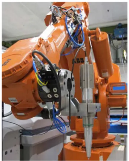
The robot that is used for picking and placing the reinforcement patches in the preform is equipped with an automatic tool changer. The tool changer makes it possible to use the same robot for moving the preform between the separate production processes in the demonstrator, as well as to hold and manipulate the ultrasonic knife, as shown in Fig. 4
5
4.2 Test Plan Development
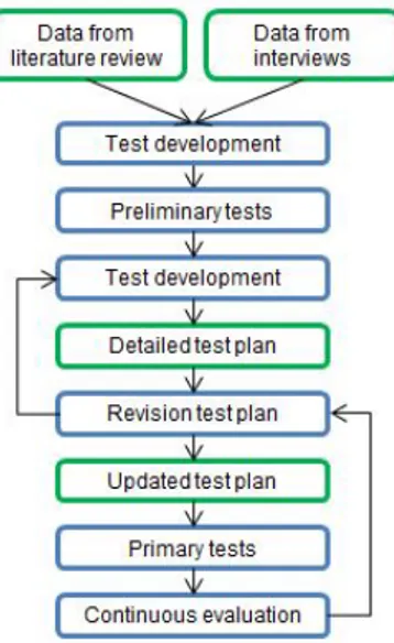
The main issue for test plan development was to determine what process parameters should be included in the tests based on if the parameters were expected to affect ultrasonic cutting in dry preforms. Furthermore, the aim was to identify what parameter values would be suitable to use as a starting point for testing and what parameter resolution would be used. The process used for test plan development is schematically explained in Fig. 5.
Fig. 5 Process description for the test plan development The literature review concerning ultrasonic cutting of composite materials and experiences from the cutting of other materials showed a lack of understanding regarding how process parameters for the cutting process could be adapted to different materials. The reviewed literature revealed a tradition of empirical testing to find a set of valid cutting parameter values.
Interviews with industrial experts in the fields of material and preforming were conducted in order to build a base of understanding of how the preforms react to cutting. The ultrasonic equipment manufacturer was interviewed about the cutting process and the equipment. Based on the information from the literature review and the interviews a draft for a test plan was developed for a preliminary test session. The main purpose of the preliminary tests was to explore the functions of the ultrasonic cutting equipment and to test a few cutting cases. Based on the experiences from the preliminary tests, parameters that were assumed to
affect the cutting process were identified. The parameters related to the knife geometry were identified as angle of attack (α), chamfer angle (β) and cutting depth. They are illustrated in Fig 6, 7 and 8.
Fig. 6 A stylized illustration of the angle of attack (α)
Fig. 7 A stylized illustration of the chamfer angle (β)
Fig. 8 A stylized illustration of cutting depth Other parameters that were considered to affect the cutting process were the preform material, level of compaction and thickness, the amplitude of the ultrasonic vibration and the relative speed between the knife and the preform (feed rate). The type of physical support of the preform during cutting was also considered to have an important influence over the cutting process.
The identification of suitable starting values and reasonable parameter resolution for the tests proved to be difficult based on the scarce background material. The starting point for several parameters were set to a presumed value based on the best
knowledge available, in many cases general recommendations from the ultrasonic cutting equipment supplier. The resolution between parameter values for different test samples was also estimated, in many cases based on the experiences from the preliminary tests. Parameter values and test resolution were determined in an iterative way, in collaboration with several industrial experts.
The physical test setup was designed to emulate the real cutting scenario, although simplifications were made. Instead of using a double-curved preform for the tests a plane, rectangular preform was used. Each test sample consisted of one single cut along the full width of the preform with one set of parameters. Only one chamfer angle was used for each test sample. In the real application, several cuts with varying chamfer angles would be needed in order to generate a faceted edge.
The test results were evaluated using qualitative evaluation methods. Qualitative evaluation methods were considered to be a suitable way to quickly find a working set of parameter settings. The cutting result of each test was examined visually and photographed for traceability. The result was evaluated and categorized to be either OK or NOT OK. The basis for the evaluation was what would be acceptable results in a quality evaluation in full volume production according to quality requirements for similar products. An OK result was considered to comply with the following requirements:
• The cut completely separated the preform into two separate parts
• The cut was a straight line
• All fibers had been cut off at the correct length, and no fibers were left uncut
• The fibers on the top and bottom surface did not show any sign of offset
• No separation of the preform layers was visible Observations from the cutting sequence and general comments about the cut quality were noted for each test.
The test plan prepared for the primary tests included a detailed description of the physical test setup, what parameters would be varied, parameter values and
resolution. It also included the fundamental guidelines for evaluating the results. The test series was planned to cover a wide area of values for each parameter. Once the primary testing began, the test plan had to be altered. For some parameters, the first few tests showed that the initial parameter value was so off that it was no use to use this value when varying other parameters. For other parameters, the proposed resolution in the test plan was too detailed, making it impossible to see any difference between the test samples. Several test samples outlined in the test plan were not performed since they were considered to not contribute with any useful result. The result of continuously altering the test plan, based on the results from the performed tests, was that a relatively good cutting could be achieved with a limited number of tests. This however was made at the expense of not being able to analyze combination effects of several parameters. From an industrial perspective, the main focus for the tests was to find a set of parameters that generate an acceptable cutting quality as soon as possible. The industrial value for carrying out an extensive test plan is limited at the moment. The data from a more extensive test plan could have scientific value as a base for developing a theoretical model describing the cutting process that can be used for identifying the optimal parameter settings.
4.3 Test Setup
The tests were performed using a commercially available system for ultrasonic cutting. The cutting equipment has a maximal power of 1200 W, a frequency of 20 kHz and variable amplitude with maximum value of 29 µm. The steel knife blade has an edge angle of 22.5°, as illustrated in Fig. 9. The ultrasonic knife was started manually a few seconds before the knife entered the material in order to remove any effects of ultrasonic excitation ramp-up. Approximately the same time was applied as a delay for ultrasonic shutdown after the knife exited the material.
Fig. 9 A stylized illustration of the knife blade with an edge angle of 22.5°
7
The ultrasonic knife was mounted on a standard industrial robot that was programmed to generate the desired linear cutting paths and angles for the tests. The cutting path was programmed so that the cutting line, and thereby the knife blade, was always parallel to the edge of the preform. The linear robot motion, generating the cutting path, was initiated at the distance Rin before the knife came into contact with the preform. This was made in order to allow for robot acceleration to full speed before commencing the cutting. The same approach was employed for deceleration after the knife exited the preform. Three different plane preforms with rectangular shape, made of the same type of reinforcement that will be used in the real double-curved preform, were used for the tests. Two of the preforms, used for the absolute majority of the tests, consisted of eight layers of 0.25 mm thick unidirectional carbon fiber reinforcement stacked in a quasi-isotropic arrangement. The two preforms were manufactured using different temperatures during the preform compaction process. This resulted in different stiffness between the preforms. The two preforms were cut into rectangular shape with a width (B) of 150 mm. Two different physical setups were used for the tests. Fig. 10 shows a schematic view of the initial test setup where the preform was extended out from the supportive table surface. Photos of the same setup are shown in Fig. 11, 12 and 13.
Fig. 10 Schematic view of Test Setup 1 where the preform is extended out from a supportive table surface
Fig. 11 Overview of Test Setup 1 with the test-preform
Fig. 12 Detailed view of Test Setup 1 from above
Fig. 13 Detailed view of Test Setup 1 illustrating the preform extended over the table surface
In the first test setup the preform was extended out from the edge of the supportive table. The distance from the table edge to the cutting line (L1) and the distance from the table edge to the edge of the preform (L2) could be varied. The position of the supporting beam was held constant during the testing.
The second setup was similar to the first, but with the main difference that the preform was supported under the whole area and that the cut was performed by cutting into the preform as well as a support material. A lightweight core material was used as cutting support. All test cuts using Test Setup 2 were performed using the same cutting line. Several cuts were made into the cutting support before actual
testing with Test Setup 2 began. These cuts generated a permanent incision in the cutting support, and therefore the additional cutting in the support material is considered to have little impact on the cutting process of the preform. In Fig. 14 a schematic view of the second test setup, where the preform was placed on top of a cutting support, is illustrated. Photos of the same setup are shown in Fig. 15, 16 and 17.
Fig. 14 Schematic view of Test Setup 2 with full cutting support under the preform
Fig. 15 Overview of Test Setup 2
Fig. 16 Detailed view of Test Setup 2 showing the core material used as cutting support
Fig. 17 Detailed view of Test Setup 2 from above 5 Results from cutting tests
The tests show that the physical setup and support of the preform during cutting has a great influence over cutting quality. The second test setup with a physical support under the entire preform generated much better cutting quality than could be achieved using the first test setup. A preform that is extended over an edge will, even with a short distance between cutting line and table edge, deflect down during cutting. This results in poor cutting quality where, in many cases, the cut does not go through the entire preform. Increasing the cutting depth has some effect but cannot compensate fully for the deflection. In a setup where the preform is extended over the supportive surface the preform stiffness is an important parameter. The stiffer preform tended to deflect less and therefore generated better cutting quality compared to the less stiff preform. The difference in cutting quality, using the same cutting parameters but changing from a stiff to a less stiff preform, is illustrated in Fig. 18, 19 and 20.
Fig. 18 Cutting result for the stiffer preform without cutting support under the cutting line
Fig. 19 Cutting result for a less stiff preform without cutting support under the cutting line
9
Fig. 20 A look into the cut generated when cutting a less stiff preform using Test Setup 1
Cutting tests using Test Setup 2 show that it is easier to find process parameters that generate a good cutting quality for the stiffer preform, although the difference is not as pronounced as for Test Setup 1. The preform stiffness has shown to be dependent on the compaction process during preform manufacturing. The compaction of the preform therefore has a direct effect on the possibility for good cutting results.
The performed tests show that the angle of attack has an effect on the cutting quality. The tests point to the fact that the angle of attack should be less than 90°, which is in accordance with the recommendations from the ultrasonic knife supplier. The tests also indicate that the optimal angle of attack is dependent on the preform stiffness. This must be further researched before a relation between angle of attack and preform stiffness can be established.
The feed rate also affects the cutting quality, and the effect is more pronounced for the less stiff preform than for the stiffer preform. Even though other parameters were also shown to affect the cutting quality, no other parameter showed as clear an influence as the level of support and the preform stiffness.
The tests show that the chamfer angel (β) does not have any distinct influence on the cutting process. For a set of parameters that generated an acceptable cut quality with a 90 degree chamfer angle, a change only in chamfer angle did not affect the cutting quality in a noticeable way. This indicates that a set of cutting parameters that generate a good cutting quality in a straight cut can also be used for cutting faceted edges by varying the chamfer angle. A cut with a 120 degree chamfer angle is shown in Fig. 21
Fig. 21 The cutting result when cutting a stiff preform with a 120 degree chamfer angle using Test Setup 2
6 Discussion
Empirical testing can be considered a customary method when dealing with ultrasonic cutting in unfamiliar materials. A great challenge in using the empirical approach is to find suitable parameter values to start the testing with and to determine the parameter resolution for varying the parameters during the tests. Interviews with experts and a literature review were conducted to find the starting position for the tests described in this article. In spite of that effort the starting parameters were shown, in some cases, to be off. For some of the parameters the test resolution in the test plan proved to be far too detailed. The test plan was altered during the testing in order to make use of this new knowledge. By altering the test plan based on knowledge received during the tests it was possible to find sets of process parameters that generated acceptable cutting quality with a limited number of tests.
The empirical approach has shown to be a practicable way to determine a set of functioning process parameters for ultrasonic cutting in an unfamiliar material. The approach can, with a limited number of experiments, lead to acceptable cutting quality. To fast being able to find parameter settings that yield acceptable cutting quality is highly desirable in an industrial application, where the development time for the production process is limited. The risk, however, is that the solution found is only one acceptable solution, and that the optimal solution that generates even better cutting quality is overlooked.
The empirical approach could be supported by a detailed theoretical model describing the cutting process in any given material. The model could be used to find the optimal cutting parameters. To find one valid solution, however, is probably faster to do using the empirical approach. Empirical tests can provide a knowledge base for developing the model. They can also create a sense of how detailed the model should be, and how detailed demands can be put on parameter resolution and other variations in the physical production system.
Since several parameters can affect the cutting quality, further testing would benefit from the use of statistical methods in order to limit the number of tests. In order to do that, quantitative methods for evaluating the test results must be developed.
The tests described in this paper found a solution area where acceptable cutting quality was achieved. Indications of what parameters have a great effect on cutting quality were also identified. This can serve as a basis for future testing, with either the purpose of testing a cutting process that generates a rounded edge through several faceted cuts, or of further exploring the cutting process in order to find an optimal parameter setting.
Another area that was discovered as part of the tests described in this paper was preform relaxation. A preform appears to lose some of its initial stiffness if it is stored for some time. Since preform stiffness has shown to affect the ultrasonic cutting process, it is interesting to further investigate this phenomenon as a part of developing the demonstrator.
7 Acknowledgments
The work presented in this paper is being carried out in projects funded by VINNOVA – Sweden’s Innovation Agency. The authors wish to thank Compraser and GKN Aerospace Applied Composites AB for their help, support and invaluable cooperation during the testing.
8 References
[1] D. Lukaszewicz, C. Ward and K. Potter "The engineering aspects of automated prepreg layup: history, present and future". Composites Part B: Engineering Vol. 43, No. 3, pp 997-1009, 2012.
[2] M. Gascons N. Blanco and K. Matthys "Evolution of manufacturing processes for fiber-reinforced thermoset tanks, vessels, and silos: a review". IIE Transactions (Institute of Industrial Engineers), Vol. 44, No. 6, pp 476-489, 2012.
[3] K. Karlsson and B. Åström "Manufacturing and applications of structural sandwich components". Composites Part A: Applied Science and Manufacturing Vol. 28, No. 2, pp 97-111, 1997.
[4] M. Lucas, A. MacBeath, E. McCulloch and A. Cardoni "A finite element model for ultrasonic cutting". Ultrasonics Vol. 44, pp e503-e509, 2006.
[5] S. Hoa “Principles of the manufacturing of composite materials”. [Electronic Resource], DEStech Publications Inc., Lancaster, PA, 2009.
[6] M. Owen, V. Middleton and C. Rudd "Fibre reinforcement for high volume resin transfer moulding (RTM)". Composites Manufacturing Vol. 1, No. 2, pp 74-78, 1990.
[7] T. Thoe, D. Aspinwall and M. Wise "Review on ultrasonic machining". International Journal of Machine Tools and Manufacture Vol. 38, No. 4, pp 239-255, 1998.
[8] R. Bogue "Cutting robots: a review of technologies and applications". Industrial Robot: An International Journal, Vol. 35, No. 5, pp 390-396, 2008.
[9] F. Campbell “Manufacturing processes for advanced composites”. Elsevier Advanced Technology, Oxford, 2004.
[10] M. Lucas J. Petzing, A. Cardoni, L. Smith and J. McGeough "Design and characterisation of ultrasonic cutting tools". CIRP Annals-Manufacturing Technology Vol. 50, No. 1, pp 149-152, 2001.
[11] Y. Schneider, S. Zahn, C. Schindler and H. Rohm "Ultrasonic excitation affects friction interactions between food materials and cutting tools" Ultrasonics Vol. 49, No. 6-7, pp 588-593, 2009.
[12] G. Arnold, S. Zahn, A. Legler and H. Rohm "Ultrasonic cutting of foods with inclined moving blades". Journal of Food Engineering, Vol. 103, No. 4, pp 394-400, 2011.