IN THE FIELD OF TECHNOLOGY DEGREE PROJECT
VEHICLE ENGINEERING
AND THE MAIN FIELD OF STUDY MECHANICAL ENGINEERING, SECOND CYCLE, 30 CREDITS
,
STOCKHOLM SWEDEN 2020
Design and system integration of a
rim jet solution utilizing DFMA
GUSTAV ADOLF ADLER
KTH ROYAL INSTITUTE OF TECHNOLOGY
Design and system
integration of a rim jet
solution utilizing DFMA
GUSTAV ADOLF ADLER
Master of Science Thesis TRITA-ITM-EX 2020:514 KTH Industrial Engineering and Management Machine Design
iii
Abstract
Moving a new innovative idea from the drawing board to production is no easy feat. The Swedish sea rescue society (SSRS) has for the past years fostered a new design solution for their jet skis, a alternative water jet that removes the centre hub and utilises rim drive technology. The "Rim Jet" would help solve problems during rescue operations while at the same time be a starting point for SSRS zero-emission vision. To make this idea reality a first prototype is necessary for a proof of concept. Previous work on this project, conducted by three master students, resulted in a design that lacked feasibility. Through the implementation of Design for manufacture and Assembly (DFMA) on the rim jet a new itteration of the design is proposed. A practical and case based analysis of the DFMA method on a novel, non mass produced prototype was preformed discussing its advantages and disadvantages to generate a feasible, lighter, simpler and more cost efficient design. Complementing the redesign of the rim jet is a complete systems analysis of the jet ski including battery evaluation, systems integration and initial testing procedures. The final rim jet design illustrates the benefits of utilising DFMA within small, single prod-uct, projects. Implementing core elements of DFMA has proven to generate similar positive effects as intended for serial mass produced products normally associated with method.
v
Sammanfattning
Att föra en ny innovativ idé från ritbordet till produktion är ingen arbiträr pro-cess. Det Svenska Sjöräddningssamhället (SSRS) har under de senaste åren fostrat en ny designlösning till sina vattenskoter, en alternativ vattenjet som eliminerar centrumnavet och använder rim-drive teknologi. Rim Jetenskul-le hjälpa till att lösa probJetenskul-lem under räddningsoperationer samtidigt som den kan agera som utgångspunkt för SSRS-nollutsläppsvission. För att förverkli-ga denna idé är en första prototyp nödvändig för att bevisa om konceptet kan fungera. Tidigare arbete med detta projekt, genomfört av tre masterstudenter, resulterade i en design som ej gick att tillverka. Genom implementeringen av Design for manufacture and Assembly (DFMA) på rimjeten kan en ny desig-niteration läggas fram. En praktisk och fallbaserad analys av DFMA-metoden på en ny, icke massproducerad, prototyp genomfördes och dess fördelar och nackdelar diskuteras för att skapa en genomförbar, lättare, enklare och mer kostnadseffektiv design. Som komplement till den nya designen kompletteras även arbetet med en en fullständig systemanalys av vettenskootern relaterat till betterilösning, systemintegration och initiala testutföranden. Den slutliga rim jet designen illustrerar fördelarna med att använda DFMA inom små, enskil-da produktprojekt. Implementeringen av kärnelement från DFMA har påvisat liknande positiva effekter som avsedda för serieproducerade produkter som normalt är associerade med metoden.
Nomenclature
F Force [N ] H Headrise [m] N Newton P Power [W ] Q Volume flow [m3/s]rpm Rotations per minute T Torque [N m]
V Volt
v Velocity [m/s] W Watt
CAD Computer Aided Design
CFD Computational Fluid Dynamics CNC Computer Numerical Control DFA Design for Assembly
DFM Design for Manufacture
DFMA Design for Manufacture and Assembly ITTC International Towing Tank Conference KTH Royal Institute of Technology
PMI Product Manufacturing Information
RDP Rim Driven Propulsion RDT Rim Driven Thruster RS Rotor Side
SKF Svenska Kullager Fabriken SS Stator Side
Contents
1 Introduction 1
2 Theory 4
2.1 Theory . . . 4
2.2 Method . . . 6
2.3 Market Overview and Related Research on RDP . . . 8
2.4 Purpose . . . 10
2.5 Limitations . . . 11
3 Frame of reference 13 3.1 Water Jet Propulsion . . . 13
3.2 Rim Driven Propulsion . . . 14
3.3 The Rescue Vessel . . . 15
3.3.1 Technical Requirements . . . 16
4 Previous Work 18 4.1 Thor Peter Andersen . . . 18
4.2 Kiran Ashok Naganalli . . . 19
4.3 Pablo Sánchez Santiago . . . 19
4.4 Magnus Munoz . . . 19
5 Redesign of the Rim Jet 22 5.1 Tools chosen for the Rim Jet project . . . 22
5.1.1 Selection of Materials and Processes . . . 22
5.1.2 Design for Assembly . . . 23
5.1.3 Design for Manufacture . . . 24
5.2 Design Overview of the Rim Jet . . . 24
5.2.1 Problematic Areas . . . 25
5.2.2 Analysis and evaluation of the initial Rim Jet design . 27 5.3 Design Modifications of the Rim Jet . . . 30
x CONTENTS 5.3.1 Rotor Tube . . . 30 5.3.2 Bearing Housing RS . . . 32 5.3.3 Cover Plate RS . . . 33 5.3.4 Sealing Positioner RS . . . 34 5.3.5 Bearing Positioner RS . . . 35 5.3.6 Rotor Blades . . . 37 5.3.7 Bearing Positioner SS . . . 39 5.3.8 Connector . . . 40 5.3.9 Bearing Housing SS . . . 41 5.3.10 Cover Plate SS . . . 42
5.3.11 Stator Blade Housning . . . 43
5.3.12 Stator Blade . . . 45
5.3.13 Pass Through Bolts . . . 47
5.3.14 Standard parts . . . 47
5.4 Modularity . . . 49
5.5 Service and Maintenance . . . 49
5.6 Final Prototype Design . . . 50
5.6.1 Comparison of Initial Design to New Design Using DFMA evaluation . . . 50 6 Production 53 6.0.1 CNC Machining . . . 53 6.0.2 Additive Manufacturing . . . 53 6.0.3 External suppliers . . . 54 6.0.4 Simplicity . . . 54 6.1 Assembly . . . 54
7 Calculations On the New Design 56 7.1 Calculations with Current Specifications and Comparisons . . 56
7.1.1 Thrust Prediction . . . 57
7.1.2 Energy Model . . . 58
8 Battery and Power Solution 63 8.1 Power Requirements . . . 63
8.2 Suggestion . . . 65
9 System Integration 68 9.1 Sections and Integration . . . 68
9.1.1 Rescue Boat . . . 68
CONTENTS xi 9.1.3 Control box . . . 69 9.1.4 Battery solution . . . 69 9.1.5 Manoeuvring . . . 70 9.1.6 Integration . . . 71 10 Testing 73 10.1 Test on Rescue Boat . . . 73
10.1.1 Bollard Pull . . . 74
10.1.2 Engine maximum rotational speed . . . 74
10.1.3 Maximum torque . . . 74
10.1.4 Delivered power at maximum rotation per minute . . . 75
10.1.5 Vessel Speed . . . 75
10.1.6 Issues with proposed methods . . . 76
11 Discussion and Conclusions 78 11.1 Discussion DFMA . . . 78
11.2 Discussion Rim Jet . . . 80
11.3 Conclusion . . . 82
11.4 Future work . . . 83
Bibliography 86
Chapter 1
Introduction
Swedish Sea Rescue Society, or SSRS, is a nonprofit organisation that con-ducts maritime search and rescue operations on Swedish lakes and at sea. They operate both individually and together with the Swedish coastguard. Their work is diverse and often demanding. It is therefore of importance that they have the right equipment for the task at hand and that said equipment does not break during operations.As of now the SSRS disposes of a wide array of sea vessels one type of which is their Rescuerunner (Swedish Sea Rescue Society, 2020). This craft is designed as a more stable and competent water scooter in sea rescue operations. It was designed and developed by Fredrik Falkman at SSRS and later bought by Safe at Sea in 2006 (Safe at Sea, 2020). The Res-cuerunner has been in regular use by SSRS ever since its conception but issues with the current solution has arisen. One of the major problems that were dis-covered by Falkman early after implementation was issues with engine failure due to entanglement from ropes and other debris in the water from ship wreck-ages. The motor blades rotate at such a speed that, when entangled, the plastic ropes melt and hardens around the motor which require expensive and time consuming repairs. A new type of engine was needed, Falkman started to fos-ter plans for one that removes the centre hub which potentially could reduce the risk of entanglement. The solution should be electric, both from a sustain-able point of view as well as a functional. For most commercial mid and large size crafts the more common screw propeller is a cheaper and simpler choice. But with the emerging trend of electrical transportation, especially within the vehicle market, there is a possibility that this will be the future for maritime transportation as well.
The first step made toward this new solution was done by Thor Ander-sen who wrote his master thesis "Design of Rim Driven Waterjet Pump for
2 CHAPTER 1. INTRODUCTION
Small Rescue Vessel" in 2014 (Andersen, 2014). Since then, three master students have worked on the project with the aim to generate a functioning solution. Despite their efforts, the Rim jet is still not feasible in its current state. With complicated, costly and impossible geometrical shapes as well as a convoluted assembly structure and high part count the design was not fit for manufacturing. To realise the rim jet a new method of deigning will have to be implemented to make the design feasible. This master thesis aims to further develop and advance the concept of the rim less water jet through the method of Design for Manufacture and Assembly (DFMA). DFMA is a combination of "Design for Manufacture" (DFM) and "Design for Assembly" (DFA). The method was developed by Geoffrey Boothryd in the beginning of the 1970s and was practically adopted within a wide array of corporations from the 1980s. DFMA is used as a driver for quality and cost improvements within product development. The method balances both the manufacturing aspect as well as the assembly aspect of developing new products with the purpose of optimis-ing the final product as a complete system.(Boothroyd, 2002). Through adop-tion of DFMA to this thesis, evaluaadop-tion of the principles will be conducted to investigate the pros and cons of DFMA on a singular product.
Chapter 2
Theory
2.1
Theory
Within the engineering community DFMA is often promoted as the optimal design method, even though no comparative studies have been performed. One example is the costly implementation of DFMA within product design soft-ware, utilising virtual reality to provide engineers with instant feedback on their work as illustrated by A. Read et al., 2017,. (Read et al., 2017) Never-theless, since the conception of DFMA, the potential and possible limitations of the method itself has been evaluated within scientific research. In a paper from 2011 . A. A. Sarmento et.al. preformed a successful case study on a Fuel Intake Cover to simplify the already relatively simple design(Sarmento et al., 2011). A second case study by N.M. Azir used DFMA and a sustainable design approach to evaluate and improve the design of a Cordless Drill(Azri et al., 2018). A third study by C.D Naiju et al. used DFMA when redesigning a shopping cart, with both reductions of the manufacturing and assembly costs as a result. (Naiju et al., 2017).
According to the examples presented above, when evaluated within itself, DFMA proves to be a successful method. The majority of case studies found within the subject are limited to small and relatively simple products. How-ever, in 1998 E. H. Gerding et al. at the Boeing Company published an ar-ticle on how to successfully implement DFMA to their already existing air-craft production, proving the method’s validity within more complex projects. (Gerding et al., 1998). Gerding et al. point out that implementing DFMA on pre-existing products can prove more difficult than when generating new concepts. Boeing’s article present many of the pitfalls that can occur during implementation, possible solutions, as well as tools and guidelines to improve
CHAPTER 2. THEORY 5
the use of DFMA within an organisation.
DFMA is mostly regarded as a tool for improving product design related to series- and mass production(Matthews et al., 2018). The foundation for this viewpoint was laid by Boothroyd, but additionally he claimed that DFMA should be applicable to low volumes as well. He argues that the philosophy of "doing it right the first time" is of even greater importance when produc-ing small quantities. However, the work presented by Boothroyd is primarily focused around mass production and improvements of already existing solu-tions, as exemplified by Boeing. When comparing the improved design to the previous an array of tests are conducted. Most frequently, designers opt to measure the assembly time and manufacturing cost of each individual part. This method of testing has proved to be an issue when assessing low quantities or a singular unit. Matthews et.al. investigates this problem using a case study involving a manufactured Paperboard Tray Press-forming prototype line. With DFMA they were able to improve the existing product resulting in less injuries when assembling the unit as well as avoiding unnecessary reassembly cycles of the design.
With the emergence of Rapid Prototyping within product development a new research area combining DFMA and Rapid Prototyping has been investi-gated. In the paper "New product development by DFMA and Rapid Prototyp-ing" by W. N. Prakash et al. a case study was used to evaluate the combination of both disciplines. DFMA was used to re-design a flow control valve. Util-ising the Rapid Prototyping, a proof of concept could immediately be tested. The outcome proved to be an optimal design with low costs, good quality and fast delivery to the customer(Prakash et al., 2014). Although the improved product presented by N. Prakash et al. is a prototype, it could be argued that it is still related to mass production in view of the fact that it is later on intended for large scale production.
Another aspect when discussing DFMA is its close but undefined con-nection to a platform- and modular design approach. F. J. Emmatty and S. P. Sarmah highlighted the many similarities between DFMA and platform-based design and questions why there has been no attempts to combine the two. Their work provides a case study implementing a modular approach through platform-based design with the principles provided in the DFMA method. Their end result proved to be an optimal product platform with reduced de-velopment time for product families(Emmatty and Sarmah, 2012).
6 CHAPTER 2. THEORY
optimal design method, even though it is mostly evaluated within itself. When designing new or improving existing products, may it be an airplane or a sim-ple toaster, there is a multitude of personnel and disciplines involved. Deciding the best way to manage these aspects of a design process is key to generating an optimal design solution. Following a common set of rules and principles can ease this interaction and improve over all work quality. DFMA has pre-viously proven to benefit both small and large scale products. Nevertheless, when examining the current status of DFMA most implementations are, in some way or another, connected to mass production even when the concept of prototyping is discussed. Because of this, there is still a research gap when discussing DFMA and a modular approach on a singular product that might never be in mass- or even serial-production.
2.2
Method
Implementing principles and methods from the book Product Design for Man-ufacture and Assembly (Boothroyd, 2002), the use of DFMA was applied to the Rim Jet to investigate the possible benefits of the method on a singular unit and improve on the current design.
Given the work by Boothroyd, the key principles of DFMA related to this project is:
• Reduce the part count; A key factor for a more cost effective and sim-pler design is the reduction of parts within the product. Fusing together parts that do not have to move relative to one another, such as the rotor tube and Bearing Positioner SS (illustrated in subsubsection 5.3.1), re-duces the part count as well as simplifies manufacturing and improves durability of the design.
• Use standardised parts and materials; To simplify assembly as well as reducing cost and finding replacement parts the use of standardised parts is essential. All bolts and screws for the rim jet are chosen with stan-dardised M thread as well as generic lengths to minimise the variations of chosen sizes. Regarding materials for the rim jet, compromises were made on the exact type of material as it depends on what the manufac-turer can offer. However, the selection between aluminium and stainless steel is of importance as their inherent proprieties and raw value will affect the final cost. As unprocessed material, stainless steel is usually cheaper then aluminium. However, the tooling cost for machining stain-less steel is much higher then aluminium. For this project weight is also
CHAPTER 2. THEORY 7
a big factor, reducing the total weight of the engine will result in a lighter total vessel and in turn a reducing in the battery needed as well as other positive property changes on the craft.
• Reducing and simplifying the number of manufacturing operations; As mentioned previously, tooling cost is a big factor when deciding on the right materials for a part. Another aspect when designing individual features is to understand the methods that will be used to create said feature. If a shape is to complicated or requires a special set of tools to accomplish it should be reevaluated and changed if possible to simplify manufacturing. One such obvious area is the notch on the rotor tube that currently requires two tubes to be welded together to accomplish.. This manufacturing method is both costly as it requires a multitude of pro-cessing steps as well as being unpredictable when regarding tolerances of the centricity of the tube.
• Simplifying the design for an easier assembly procedure; Both first as-sembly as well as later modifications would benefit from a design that optimises simplicity during assembly. Especially during the prototype phase of the design there might be a wide array of changes that will have to be made later to optimise the deign. Designing in a way that is sim-ple to assemble and disassemble will reduce both manufacturing cost as well as future modification cost.
• Design modular assemblies; A modular approach ties together with the previous simplification of the design. Within this project one major area of modality is the blade construction and configuration. However, this blade design has yet to be tested in a real life scenario. It is therefore essential to design in a way that simplifies future changes made to im-prove the fluid properties of the blades. Therefore, a modular approach is implemented especially within that area to account for possible future changes.
Presented in Chapter 5 all individual parts within the rim jet are evalu-ated in regards to previously mentioned areas of DFMA. No aspect can be evaluated without regarding the others and a design decision should always be weighted against other aspects and most of the times compromises must be made to reach an optimal design.
With the use of CAD software, the previous design was improved through implementation of iterative DFMA. Using methods for rapid manufacturing
8 CHAPTER 2. THEORY
and modular design provided in the book Collaborative Engineering (Kam-rani and Nasr, 2008) in tandem with DFMA presented in the paper written by Prakash et al. (Prakash et al., 2014) both the Rim Jet as well as the Rescue Vessel was improved as a complete system.
Utilising this hands on case of a single unit rim jet, DFMA can be eval-uated from a new perspective and providing insight to its pros and cons even for small quantities of produced units.
Finally, using recommendations provided by the International Towing Tank Conference, cost efficient and simple testing methods were derived.
2.3
Market Overview and Related Research
on RDP
For the past few years new actors on the electrical maritime market have been emerging and the public interest in electrical transportation has never been higher. In Sweden there are two big actors, Candela (Candela, 2020) and XShore (XShore, 2020). Their products are both completely electric but at-tempts to solve the issues with electrical driven water crafts in different ways. Candela has chosen to implement foils in their design to overcome the drag from water on the hull, whilst XShore has chosen a bigger battery to counter the resistance from the water. Currently both of these companies use a regular propeller for propulsion, this is also the case for other companies on the market such as Strana (Starna, 2020) and HWILA25 (Hwila25, 2020).
Another type of water propulsion is the rim driven propeller, most com-monly used on bigger container ships as prow and stern thrusters to move the ship sideways. One of the leading manufacturers for smaller water crafts are the German company Torque-Jet (Torque-Jet, 2020). They have adapted the regular bow thruster to be used as a propulsion motor by reshaping the blades and adapting other properties to be more effective in one rotational direction. Furthermore, a French company named FinX have developed a membrane mo-tor that removes any rotating parts and instead uses a wave-like motion to move the water through the engine (FinX, 2020). The motor is said to be safer and more robust than conventional propellers. The current models are still in de-velopment but pre-orders can be made.
CHAPTER 2. THEORY 9
Research on the subject of rim driven propulsion as a valid substitute for propellers as propulsion is relatively scarse, although companies that are cur-rently developing and manufacturing this type of machine most certainly have their own confidential research on the subject. There have been research done by the School of Marine Science and Technology in China where they, much like Andersen, compared hub-type and hub less rim driven thrusters to anal-yse efficiency and other aspects of the configuration(Song et al., 2015). Their research concluded that a hub-less design would be have an increased thrust, a higher torque and a smaller thrust ratio compared to using a hub in the middle of the rotor. The same finding was also concluded in the work by Lan et al. in their work "Study on Hydrodynamic Performance of Hubless Rim-Driven Propulsors with Variable Parameters"(Lan et al., 2017). However, both of the studies was preformed on a standard rim-driven thruster at relatively low ro-tational speeds (approximately 1000 rpm) and not with a jet-configuration. Another research project from University of Southampton investigated the rotor–stator interaction in rim driven thrusters to better understand the fluid dynamics related to this design solution (Dubas et al., 2015). Dubas et al. conclude that the methods used in the study lack in accuracy and that further studies on the subject should be conducted to better understand and predict the effects of rotor–stator interaction.
In 2017, engineers S. Fletcher and R. Hayes at Frazer-Nash Consultancy presented a pros and cons discussion on the future of electrical propulsion. They state that the shipping industry has seen a shift during the recent years in the use of technology and that integration of electrical propulsion is emerging (Fletcher and Hayes, 2017). They also discuss the potential of Rim-Driven Propulsors (RDP) and the benefits that this technology could have for the fu-ture of ship architecfu-ture. One key area Fletcher and Hayes present is the effi-ciency potential of a RDP. More specifically, the lack of a centre hub or shaft that would reduce the potential energy loss from turbulence, while at the same time increasing the control over rapid changes in the rotational speed. In a paper from The Hong Kong Polytechnic University Cheng et al. discuss zero emission electric vessel development. It is concluded that the emerging trend of electrical water vessels will result in the replacement of short range vessels within the next ten years (K.W.E. et al., 2015).
In a paper review written by Yan et al. from 2017 it is concluded that "Rim-driven thruster (RDT) propulsion device has several notable advantages compared to the traditional shafting propulsion plant
10 CHAPTER 2. THEORY
and POD propulsion plant (e.g., better working principles, eas-ier product maintenance, and occupying less engine room space), but also that high-power RDT propulsion devices are considerably more complex. High-power driven motors and high-load carry-ing, wear-resistant, water-lubricated bearings have yet to be fully developed." (Yan et al., 2017).
As stated above, rim driven propulsion has potential to be the future of water propulsion if the specified technical obstacles can be overcome. In their review, a number of cases are listed that research the use of rim driven, as well as shaft less rim driven thrusters. In their list, only the work done by Andersen investigates the use of rim thrusters in a water jet configuration.
2.4
Purpose
In a world where climate change is affecting everyone, new leaps for a more sustainable future is made every day. Electrical cars are now something most have grown accustom to, although this was not the case 10 years ago. As mentioned earlier, Cheng et. al predicts in their paper from 2015 that in ten years electric solutions will be replacing small short range vessels. Moreover, Dubas et al. concludes in their paper that further research in the area of rotor stator interaction regarding rim driven propulsion would be of considerable value to a number of applications (Dubas et al., 2015).
This project builds on previous work on the Rim Jet solution first started by Thor Andersen six years ago with the aim to theoretically validate if a Rim Jet solution for SSRS could be sufficient. Andersens thesis concluded that a Rim Jet design could work in practice with some minor efficiency set back because of the loss of a centre hub (Andersen, 2014). Following Andersen was Pablo Sánchez Santiago and most recently Magnus Munoz. Munoz suggested that future research should focus on a prototype validation and investigate the integration of the Rim Jet with the Rescue Boat.
Before production can begin the design of the Rim Jet must be finalised, as-suring that all parts can be both manufactured individually and assembled as a unit. The production methods chosen must be reasonable in cost and accuracy as the budget for SSRS is limited. Moreover, the assembly and disassembly of the product must be valid and optimised for changes and future improvements. The method of DFMA is most commonly used for products in large quantities, however in this research core principles will be used to investigate and evalu-ate the potential of DFMA on a single prototype, in this case the Rim Jet with
CHAPTER 2. THEORY 11
hopes that the philosophy of DFMA will improve the overall design.
Hence, the purpose of this project is to further develop and advance the concept of a rim less water jet using DFMA. Both for the potential use within SSRS as a tool for rescue operations, but also to further investigate rim driven propulsion regarding RDT as a valid option for smaller maritime vessels which operate at higher speed. Through adoption of DFMA to this case study, eval-uation of the principles will be conducted to investigate the pros and cons of DFMA on singular product and fill the research gap within this area. The project will also include a proposal for system integration and preparations for upcoming testing, with the aim to provide recommendations for up coming work on the Rim Jet and Rescue Vessel project as a whole.
2.5
Limitations
The limitations for this thesis are:
• No major changes will be made to the current design. However, reducing and simplifying the current drawings for manufacturing will be done. • The methods used for manufacturing are chosen in regards to their time
efficiency and cost for one unit. It might therefore be important to change manufacturing methods for future products to reduce production costs. • No Computational Fluid Dynamics (CFD) simulation will be made within
this project as the time for this project is limited.
• The current engine provided by SSRS for the project has a smaller hub diameter than previous calculations done by students have accounted for. However, no changes to the engine can or will be made at this stage and the goal is therefore in this thesis to design a working prototype with the current engine.
Chapter 3
Frame of reference
3.1
Water Jet Propulsion
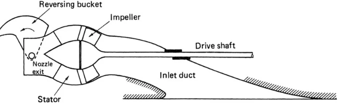
Water jet propulsion as a concept dates back to 1661, but it is only in later years that its potential use on larger water vessels have been considered Carl-ton (2012). A water jet utilises NewCarl-tons second law of motion “Every action has an equal and opposite reaction”. Water is drawn in from underneath the craft, into the pump house and then forced out through the exit nozzle. This flow of water generated by the rotor is what pushes the craft forward. See Fig-ure 3.1
Figure 3.1: Principal drawing of a water jet Carlton (2012)
Water enters the inlet tube from underneath the craft, it is then lead into the rotor blades and accelerated towards the rear. The rotating impeller blades are formed like screws to transfer the energy from the engine to the water, whilst the stator blades have a more axial angle to straighten the flow of the water
14 CHAPTER 3. FRAME OF REFERENCE
for higher efficiency. Water then exits the jet from the steering nozzle which usually is used to control the direction of water and hence steer the vessel. To reverse the flow on a water jet a reversing bucket is used. Through a mechanic or hydraulic actuator it is possible to go from full forward thrust to full reverse within seconds. For some designs of the reverse bucket, it is also possible to use the full capacity of the water jet when manoeuvring the craft by spilling some of the water backward and forward at the same time. This makes it possible to rotate the vessel without moving it backward or forward.
3.2
Rim Driven Propulsion
Figure 3.2: Drawing from the German patent f or a RDT (Kort, 1940)
Rim Driven Thruster (RDT) or Rim Driven Propulsion (RDP) is an alter-native solution to the traditional shaft transmission solution. The rudimen-tary principal of a RDT is, compared to classical propulsion techniques, to move the origin of rotational force from a centre axle to the outer rim of the tube. This means a compleate re-moval of the drive shaft as depicted in Figure 3.1. RDP as a concept has been around since the early 20th cen-tury, with different design solutions and patents. Shown in Figure 3.2 is a German patent from 1940 that was meant to be powered by electricity. It should be noted that the design de-picted still utilises a center hub for blade stabilisation in contrast to the
rim jet design in this project. Other transmission solutions tried to utilise gear-boxes to transfer the energy but proved to generate to much friction and energy losses. (Satterthwaite and Macy.Jr, 1970).
RDTs of today primarily use magnets to set the rotor in motion. The hous-ing, illustrated as b) in Figure 3.2 drawing Abb.1 is static and mounted to the craft and consists of several electromagnets. The rotating ring a) has multiple small permanent magnets mounted around the blades on a tube. By altering the current through the electromagnets the rotor is set in motion, in the same was as any electrical motor.
CHAPTER 3. FRAME OF REFERENCE 15
3.3
The Rescue Vessel
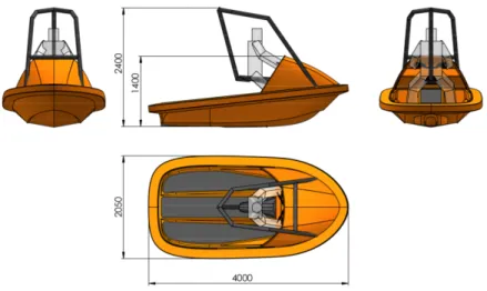
Figure 3.3: The original Rescuerunner developed by Fredrik Falkman. Swedish sea rescue society (2020)
Currently in use by the SSRS is the Rescuerunner(SafeAtSea, 2020), a small water craft designed by Fredrik Falkman at SSRS for their operations. The boats hull is designed to be stable and durable in harsh sea while providing the driver with easy manoeuvrability and power. The Rescuerunner is built to access places larger crafts can not and the relatively small size also makes it easy for one person to operate.
16 CHAPTER 3. FRAME OF REFERENCE
Since then, the ownership and production of the Rescuerunner has been acquired by Safe At Sea, however Fredrik Falkman has been developing a new type of rescue craft. This water craft is slightly bigger than the original Res-cuerunner but is still as reliable and durable as its predecessor. Currently there has only been one prototype produced with the intention to work as a testing unit for the potential Rim Jet.
3.3.1
Technical Requirements
In the beginning of this project in 2014 SSRS decided on a list of requirements that had to be met for them to determine if the final vessel would be of use to them. In Table 3.1 the requirements are listed.
Table 3.1: Requirements set by SSRS on the final vessel
SSRS Requirement Value Unit
Bollard pull (thrust) 4 kN Engine maximum rotational speed 4000 rpm
Maximum torque 132 Nm Delivered power at maximum rpm 55 kW Vessel speed 20-25 knots Displacement 800 (1250) kg
Chapter 4
Previous Work
4.1
Thor Peter Andersen
Figure 4.1: Blade design by Thor Peter Andersen
Thor Peter Andersen, a master stu-dent at Chalmers University of Tech-nology, laid the foundation of which all subsequent projects build on. In his paper "Design of Rim Driven Waterjet Pump for Small Rescue Vessel" Andersen simulated differ-ent design possibilities of the Rim Jet and aimed to verify if a hub-less Rim Jet is theoretically possible in regard to the requirements set by the SSRS. He concludes that the Rim Jet could be a feasible solution, but that effi-ciency and bollard pull (thrust at zero
knots) will be an issue due to the size of the rotor diameter. Andersen proposed future work to improve on the cavitation properties of the system and that, if possible, the best improvement to the design would be to increase the diameter of the rotor as well as the outlet. In addition he also pointed out that the lack of accuracy and exact data on the duct losses could potentially mean that a real prototype of the Rim Jet could have a higher bollard pull if duct losses are lower than his simulations concluded and that future research would benefit from further investigations within this area.
CHAPTER 4. PREVIOUS WORK 19
4.2
Kiran Ashok Naganalli
Shortly after the work by Andersen was published a student from KTH be-gun working on a first design for the Rim Jet. However, this work was never finished as the student left Sweden without notice and was never heard from again. What was estimated to be almost half of a finished report was received by SSRS but little have been used from said work.
4.3
Pablo Sánchez Santiago
Taking over after Andersen was Pablo Sánchez Santiago who made the first technical concept of the Rim Jet. He used bearings from SKF and seals from Trelleborg Sealing Solutions together with custom designed parts that had to be made separately. The work was primarily focused on determining the most fitting bearings and seals that would withstand the forces and rotational speed of the engine, whilst taking into account the importance of minimising the number of systems, optimising performance and making the end product as compact as possible.
Figure 4.2: Rim Jet design by Pablo Sánchez Santiago
4.4
Magnus Munoz
The work done by Sánchez Santiago was then handed over to Magnus Munoz for further development. In his thesis "Mechanical design and manufactur-ing evaluation of a shaftless waterjet propulsor" the primary objective was to
20 CHAPTER 4. PREVIOUS WORK
evaluate and finish the current design proposed by by Sánchez Santiago and investigate different manufacturing techniques that could be used to produce the first prototype. Focus was directed toward reviewing and editing the pre-vious design and using Finite Element Method (FEM) to evaluate the concept. In addition, M˜unoz initiated a collaboration with SKF, a partnership that has continued throughout this project. SKF is intending to manufacture the first prototype of the Rim Jet.
Chapter 5
Redesign of the Rim Jet
Utilising the DFMA tools presented by Boothroyd, key elements suitable for this project were identified and chosen. For the initial phase, manufacturing techniques and materials offered by SKF were inspected and evaluated. To be-gin the DFMA procedure, the design by M˜unoz was inspected, analysed and evaluated. Problematic areas were identified and assessed in relation to other parts of the design. The Rim Jet was then broken-down into its individual parts and modified for improvements, both within each part, as well as improving the complete system. During this phase an array of areas had to be considered, starting with DFM and DFA as well as modular aspects and functionality re-lated to the performance of the engine. The final design aims to simplify and optimise the Rim Jet for an initial prototype that is simpler, faster and cheaper to make.
5.1
Tools chosen for the Rim Jet project
DFMA can be implemented with varying degrees on a project or product. Boothroyd segments the method into three main areas. First an initial design phase, secondly, Designing for Manual Assembly and finally, Design for Man-ufacture depending on what manufacturing method that is intended for each individual part. For this project, certain areas within each segment has been identified as applicable and is presented as follows.
5.1.1
Selection of Materials and Processes
Boothroyd presents an issue that, when conceiving new parts, engineers often tend to only consider the materials and tools they are most familiar with. This
CHAPTER 5. REDESIGN OF THE RIM JET 23
might exclude methods that could prove more economic. Therefore, a first step is to identify all possible manufacturing techniques available. Within this project, the manufacturing methods and techniques are limited to the tools available in the workshop at SKF. Following is a list of available manufacturing techniques:
• Manual and CNC Turning • Manual and CNC Milling • Soldering
• Welding
• 3D printing (plastic)
These were all presented and inspected during a meeting in their facility in Gothenburg. Choosing the right tool for manufacturing is essential when de-signing the individual parts. Unnecessary shapes and geometrical forms can result in complicated production steps, all resulting in a higher final cost. Im-possible shapes or unreachable tolerances are also areas that have to be con-sidered when deciding on a manufacturing method and part design.
The second area of consideration presented by Boothroyd is the material selection. Different methods of selecting materials are presented, however for implementation on this initial prototype, material selection will be generalised to Stainless steal and Aluminium as this is the materials offered by SKF.
5.1.2
Design for Assembly
DFMA can be split up into two segments, Design for Assembly and Design for Manufacure. There is a wide array of aspects that have to be considered when designing for assembly. The core goal of DFA is to minimise the num-ber of parts and the time needed for each operation during assembly. This can be related to eliminating adjustments, designing self aligning- and self lo-cating parts, minimise the need for reorientation during assembly and other time consuming operations. Boothroyd provides illustrations and guidelines on design solutions to improve the assembly methods and structures. For a prototype project like the Rim Jet, the lack of a production line makes com-paring assembly time and production costs difficult. However, future changes and upgrades to the Rim Jet will benefit from a simple and easy assembly process as well as improved quality and modularity.
24 CHAPTER 5. REDESIGN OF THE RIM JET
5.1.3
Design for Manufacture
When assessing the manufacturing aspect of a product, the focus is aimed to-ward the methods, tools and procedures needed to produce the individual com-ponents that makes up a larger assembly. As discussed earlier, deciding on the optimal material to use for each individual part is a fundamental part of DFM. Nevertheless, when evaluating a material for selection, the manufacturing as-pects should be taken into consideration. For example, choosing a cheaper material could result in a more costly manufacturing process. This is because unsuitable or low quality materials might require special tools or equipment to process, as well as potentially increasing unnecessary manufacture waste.
Bothroyd provides a comprehensive guide on how to design depending on the chosen manufacturing method. Within this project a primary focus will be on the chapter "Design for Machining" as this is the main production technique at SKF.
5.2
Design Overview of the Rim Jet
Figure 5.1: Section view of the complete Rim Jet assembly by Munoz
Displayed in Figure 5.1 is the complete engine as designed by Munoz. The assembly consists of 18 individual non-standard parts that require manufac-turing. For this thesis the Outlet Tube, Steering Nozzle, Reversing Bucket Support and Reverse Bucket have been excluded to simplify manufacturing of the prototype. This decision reduces the total number of custom parts to 14 before design modifications.
CHAPTER 5. REDESIGN OF THE RIM JET 25
5.2.1
Problematic Areas
After a consultancy meeting with Ulf Mansnerus from SSPA, who was in-volved with the project in the beginning of 2014, problem areas regarding fluid dynamics and Rotor and Stator positions were identified from the initial design done by Munoz. Next, a detailed examination of each individual part as well as their respective interactions to other parts was examined using a perspective of optimising manufacturing, assembly, disassembly and modu-larity. This was done to prioritise and evaluate necessary changes that could affect other parts of the design. Following are illustrations and descriptions of potential problem areas both in relation to performance as well as production, assembly and modularity.
Figure 5.2: Circle indicates the slot for the Rotor blades
One critical manufacturing issue identified on the Rotor tube, se Figure 5.2, is a slot designed for inserting the rotor blades to. A slot this deep would not be possible to manufacture with a CNC lathe from a single piece of metal. Munoz tried to so solve this by splitting the rotor tube in two sections, manufac-turing each separately and then welding them together in the middle. However, with a rotational speed of approximately 4000rpm any tolerance deviations re-garding centricity could result in vibrations within the engine and with time, fatigue and stress, could result in malfunction. The individual rotor blades would also be complicated to insert together both during first assembly, dur-ing production, as well as later durdur-ing design changes, modifications, upgrades or reparations.
26 CHAPTER 5. REDESIGN OF THE RIM JET
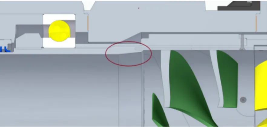
Figure 5.3: Rectangle indicates the problematic area between Rotor tube and Stator housing.
Another issue on the initial design is the gap between the Rotor tube and the Stator housing, se Figure 5.3. When the rotor spins and pushes water back-wards through the engine pressure builds up downstream. When the diameter shrinks during the stator phase pressure builds even further. Sand and other debris within the water will be pressed outwards because of the centrifugal force as well as the pressure within. There is therefore a potential risk that the gap between the rotating Rotor tube and the static Stator housing will be clogged with sand and particles, diminishing the performance of the engine and its life expectancy. This gap also requires high tolerances for both the Ro-tor tube as well as the StaRo-tor housing to ensure free rotation from one another and precision processes like this require more time and expensive tools.
Figure 5.4: Circle indicates the area change between inlet and Rotor blades
When designing a jet propulsion system it is essential to go from a larger inlet diameter and compressing the fluid downstream to generate a higher
ve-CHAPTER 5. REDESIGN OF THE RIM JET 27
locity. Area changes need to be correct to not generate wall turbulence and other issues that reduce efficiency and performance. One such issue was found between the beginning of the rotor tube and the transition to the rotor blade as shown in Figure 5.4. The area change would most probably result in a vacuum right after the edge and induce a turbulent flow that would decrease the effi-ciency of the engine. The change could also have effects on the rotor blades causing vibrations or loss in efficiency.
Figure 5.5: Current Rotor Tube
Reducing part count is essential for DFMA and identifying unnecessary parts before production is key to reducing development costs. In this design, the two Precision lock nuts, se Figure 5.5 was identified as not providing any value to the design. The purpose of the nuts was to lock the bearings in to place on the rotor tube. However, that is already accomplished by the bearing housing RS (Rotor Side) as well as bearing housing SS (Stator Side) on each side of the engine that forces the bearings in to place with the pre tensioning springs on the SS side as well as the bearing configuration chosen by M˜unoz.
5.2.2
Analysis and evaluation of the initial Rim Jet
de-sign
Applying DFMA to the Rim Jet design in practice requires a decomposition of the Rim Jet to its constituent parts and a examination of them in respect to other components. Normally when implementing DFMA and in particular DFA, an assessment of assembly time as well as specific cost for each indi-vidual part are taken into consideration. For this project however this is not an option. Instead, an evaluation of the number of parts and their connections to other parts is assessed. The "Number of interfaces" is derived by
exam-28 CHAPTER 5. REDESIGN OF THE RIM JET
ining each part individually and determining the number of places were the part physically interacts with other parts. Adding to this, a weighting method depending on the expected cost relative to other parts is conducted to evaluate if changes made will reduce the overall cost of the parts needed and not only the number of parts. The weight is ranked with L for Low, M for Medium and H for high. The ranking is set depending on several elements, material cost, weight, production time as well as how hard or easy it is for SSRS to acquire each part. The parts are listed in order of assembly and the engine will act as the base platform.
CHAPTER 5. REDESIGN OF THE RIM JET 29
Table 5.1: Analysis before design changes
Part number Part name Number of parts Number of interfaces Cost (L/M/H) Wn Wp
1 Engine 1 3 H 9 27 2 Tube 2.1 Rotor tube 1 17 M 3 51 2.2 Bearing possitioner RS 1 2 M 3 6 2.3 Bearing possitioner SS 1 3 M 3 9 2.4 Rotor blades 4 8 H 9 72 2.5 Bot M4 L18 8 32 L 1 32 3 Connecting 3.1 Connector 1 24 M 3 72 3.2 Bearing Housing RS 1 28 H 9 252
3.3 Pass throgh bolts 12 24 L 1 24
3.4 Nut M6 12 24 L 1 24
4 Rotor side of engine
4.1 Bearing RS 1 5 H 9 45 4.2 Precition nut RS 1 2 M 3 6 4.3 Sealing positioner RS 1 4 M 3 12 4.4 Sealing RS 1 2 H 9 18 4.5 Cover plate RS 1 14 M 3 42 4.6 Bots M6 L30 12 24 L 1 24
5 Stator side of engine
5.1 Bearing SS 1 33 H 9 297 5.2 Precition nut SS 1 2 M 3 6 6 Bearing Housing 6.1 Bearing Housing SS 1 72 H 9 648 6.2 Springs 30 60 L 1 60 6.3 Sealing SS 1 2 H 9 18 6.4 Cover Plate SS 1 13 M 3 39 6.5 Bolt M4 L14 12 24 L 1 24 6.6 Gortex vent 1 1 L 1 1
7 Stator side of engine 2
7.1 Bolt M6 L45 12 24 L 1 24
8 Stator
8.1 Stator Blade Housing 1 43 M 3 129
8.2 Stator Blades 6 30 H 9 270 8.3 Bolt M3 L4 12 24 L 1 24 8.4 Bolt M4 L12 12 24 L 1 24 8.5 Bolt M6 L14 12 24 L 1 24 Total 162 592 2304 Wp = Wn∗ Nn (5.1)
Where Wp = Weighted value, Wn= The Weight (1/3/9) and Nn= Number of
parts
It is difficult to draw any initial conclusions from Table 5.1. The aim is to reduce the total value of each segment to optimise the design as a reduced number of parts will potentially reduce the total cost of the Rim Jet and a
30 CHAPTER 5. REDESIGN OF THE RIM JET
reduction in interfaces could reduce assembly time as well. Using a weighted system makes it possible to rank a simple change to a complicated and costly part higher then a small change to a simpler part. It should also be observed that the assembly structure is divided into eight sections, with each section being a subsystem assembled to then be attached to the main assembly.
5.3
Design Modifications of the Rim Jet
Following is a decomposition of all parts presented in the work by M˜unoz. Connected to every part is a description of issues regarding DFMA and the changes made. For a detailed comparison see blueprints in Appendix A.
5.3.1
Rotor Tube
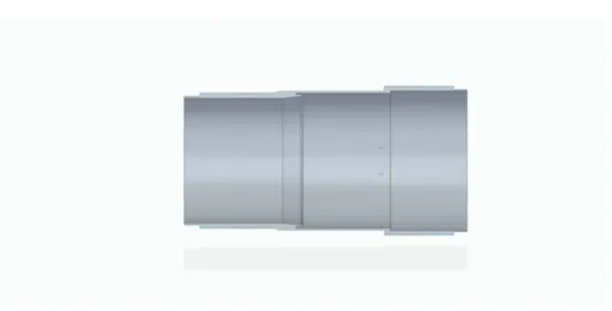
Figure 5.6: Section view of the Rotor Tube designed by M˜unoz
The purpose of the rotor tube is to transfer the rotational force from the rim motor to the rotor blades. It slides in and fits inside the rim of the motor and is fixated with bolts. The rotor blades slide in from the right in Figure 5.6 and are fixated through bolts and a groove in the wall of the tube. The tube has outside threads for the bearing holders as well as high tolerance surfaces where the seals slide on.
CHAPTER 5. REDESIGN OF THE RIM JET 31
Modifications
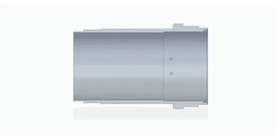
Figure 5.7: Current Rotor Tube
A number of modifications were made to the rotor tube to fit the improved design. Foremost, the complicated axial slot for the rotor blades have been removed. Together with the removing of the rotor-slot, the diameter change at the same place has also been removed. Instead, now the tube has one fixed diameter from the inlet until it reaches the beginning of the stator blades. This change also made it possible to increase the thickness of the rotor tube wall around the engine-rotor. The rotor blades were also moved backwards, cor-recting the potential issue with sand and other particles travelling in between the rotor and the stator in the initial design. This change also improves the modularity of the engine where it now is easy to access and exchange both ro-tor or staro-tor blade if damaged. For further changes see Figure 5.6 and Figure 5.7.
32 CHAPTER 5. REDESIGN OF THE RIM JET
5.3.2
Bearing Housing RS
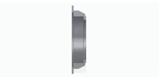
Figure 5.8: Section view of the Bearing Housing RS by M˜unoz
Connecting the engine to the rescue craft is the Bearing Housing RS. It also contains the Bearing Seat for the Front Bearing.
Modifications
Figure 5.9: Current Bearing Housing RS
The overall design of the Bearing Housing RS has not changed substantially. The most notable change is the axial shortening of the part that reduces the
CHAPTER 5. REDESIGN OF THE RIM JET 33
weight of the piece from 28kg to 20kg. The holes for the pass through bolts have also been changed to threaded holes to simplify assembly when the bear-ing is inserted in its designated place. The gaskets have been removed from this initial prototype design to simplify both assembly and production. Instead a silicon compound is used in the prototype to ensure a complete seal when assembled. This type of sealant is cheaper and easier to apply to a prototype, however it is not as reliant as a toric joint and should be reevaluated for a potential future rim jet model.
5.3.3
Cover Plate RS
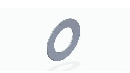
Figure 5.10: View of Cover Plate RS by M˜unoz
To lock the sealing positioner and bearing in place a cover plate is used, a simple round disk bolted to the bearing housing RS.
34 CHAPTER 5. REDESIGN OF THE RIM JET
Modifications
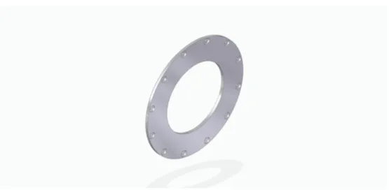
Figure 5.11: Current Cover Plate RS
No drastic changes were made to the cover plate RS, some dimensions have been altered to fit the new design of the bearing housing RS.
5.3.4
Sealing Positioner RS
Figure 5.12: Section view of Sealing Positioner RS by M˜unoz
The seals used in this design are manufactured by Trelleborg. To hold the rotary seals in place a sealing positioner is placed within the bearing housing and fixated in place by the cover plate.
CHAPTER 5. REDESIGN OF THE RIM JET 35
Modifications
Figure 5.13: Section view of current Sealing Positioner RS
For the sealing positioner RS the axial length of the part was shortened to reduce weight. The material is also changed to aluminium as this piece will not endure heavy load. This reduces the weight from 5.4 kg to slightly below 1 kg. The overall functionality is not changed because of the dimension restrictions from the previously chosen rotary seals.
5.3.5
Bearing Positioner RS
36 CHAPTER 5. REDESIGN OF THE RIM JET
Transferring the axial bearing forces from the engine to the hull means using a bearing positioner on the right side of the bearing. It slides on from the left after the rotor tube has been attached to the motor rim.
Modifications
Figure 5.15: The new Rotor Extention
To ensure simplicity for production the bearing positioner RS was renamed the rotor extension 5.15. With the changes on the Rotor Tube a lighter and simpler part was designed to fulfil the same purpose.
CHAPTER 5. REDESIGN OF THE RIM JET 37
5.3.6
Rotor Blades
Figure 5.16: Rotor Blades by M˜unoz
Converting the rotational momentum from the engine to the water, a collection of blades are used. These are all individually made on separate sheets and then placed within the tube and fastened with bolts radially through the rotor tube.
Modifications
38 CHAPTER 5. REDESIGN OF THE RIM JET
Figure 5.18: View of the complete Rotor Blades
The rotor blade is, together with the stator blade, the most complex part of the engine and choosing a suitable production technique is difficult. Instead of making individual blades that slide into the engine separately, a 3D printing solution is used where the blade and tube is made in one single piece. Initially they will be made from durable plastics and if needed treated with a cover of fiberglass to strengthen the blades. In the long term there are options such as composite 3D-printing as well as metal 3D-printing that might be suitable, although the later would be more costly. It is fixated with bolts going through the flange at the rear end of the rotor tube to ease installation and maintenance.
CHAPTER 5. REDESIGN OF THE RIM JET 39
5.3.7
Bearing Positioner SS
Figure 5.19: Bearing Possitioner SS by M˜unoz
On the opposite side of the motor is another bearing positioner, bearing posi-tioner SS. It connects the axial bearing forces from one side of the engine to the other. This one is bolted with the same screws that are used to fixate the rotor blades.
Modifications
This part has been removed and instead it has been combined with the rotor tube as it fills no purpose to be a separate unit.
40 CHAPTER 5. REDESIGN OF THE RIM JET
5.3.8
Connector
Figure 5.20: Section view of the Connector by M˜unoz
The connector has two main tasks, connecting the bearing housing SS to the engine and acting as a mounting ring for the reverse bucket.
Modifications
Figure 5.21: Section view of the current Connector
CHAPTER 5. REDESIGN OF THE RIM JET 41
5.3.9
Bearing Housing SS
Figure 5.22: Section view of the Bearing Housing SS by M˜unoz
As previously explained the bearing housing is made to house the bearings and in this case also the rotary seal. For this side of the engine the housing is also equipped with springs to create a pre-tension on the bearings. A threaded hole on the top makes adding lubricating oil easy.
Modifications
42 CHAPTER 5. REDESIGN OF THE RIM JET
As with most major parts, the axial length have been reduced and hence also re-duced the weight of the piece. The chosen material was changed to aluminium to further cut down on weight. As this part is subjected to lower amounts of force than its counter part, bearing housing RS, this change should not affect the strength and durability. Most other aspects of the part stayed the same. This relates to holes for connecting other parts, springs for bearing pre-tensioning, seal and bearing seats.
5.3.10
Cover Plate SS
Figure 5.24: Cover Plate SS by M˜unoz
CHAPTER 5. REDESIGN OF THE RIM JET 43
Modifications
Figure 5.25: Current Cover Plate SS
The primary change was the reduction of connecting holes to the bearing hous-ing SS. This was done because there is no large forces involved and the pur-pouse of this part is to lock the rotary seal in place. Small dimensional changes were also made.
5.3.11
Stator Blade Housning
44 CHAPTER 5. REDESIGN OF THE RIM JET
The last part before the outlet nozzle is the stator blade housing. It connects to the bearing housing SS with bolts and tunnels the water to a smaller outlet area.
Modifications
Figure 5.27: Section view of current Stator Blade Housing
Drastic changes were made to the stator blade housing to adapt to the new rotor tube design. The new design fits the Stator blades behind its connection to the bearing housing SS. The new design is significantly easier to manufacture and does not require as high tolerances as the previous. To lower the total height of the engine, the part was changed from stainless steal to aluminium. As this is a part that might wear out faster than others, a future design might change the back to stainless steal for a more reliable design.
CHAPTER 5. REDESIGN OF THE RIM JET 45
5.3.12
Stator Blade
Figure 5.28: Stator Blade by M˜unoz
When exiting the rotor blades the water pushed through will have a rotational speed as well as the axial speed. To increase efficiency of the engine, this rotational speed is reversed back to axial by the stator. This, together with the diameter change from inlet to outlet is what constitutes a jet configuration. The six separate blades are made individually and fastened with four bolts for each blade to the stator housing.
46 CHAPTER 5. REDESIGN OF THE RIM JET
Modifications
Figure 5.29: Section view of current Stator Blade
Figure 5.30: Complete view of current Stator Blade
The same changes made to the Rotor Blades was made to the stator blades. To ease manufacturing, installation and maintenance all of the blades are manu-factured on the same tube that slides into place in the stator holder. It is fixated rotational and axially with bolts screwed axially on the flange at the inlet of the stator blade housing.
CHAPTER 5. REDESIGN OF THE RIM JET 47
5.3.13
Pass Through Bolts
Figure 5.31: Pass through bolts designed by M˜unoz
Connecting both sides of the engine is the Pass Through Bolts, that runs through the engine and is locked with nuts from the Connector Side.
Modifications
Instead of manufacturing bolts, a threaded rod with a bolt on the end will be used to clamp the connector and the Bearing Housing RS around the engine-stator.
5.3.14
Standard parts
48 CHAPTER 5. REDESIGN OF THE RIM JET
Part Identification Provider Quantity
Angular Contact Ball Bearing 71940 ACD/HCP4A SKF 1
Angular Contact Ball Bearing 71944 ACD HC SKF 1
Precision Lock Nut KMT 40 SKF 1
Precision Lock Nut KMT 44 SKF 1
Rotary Seal (rotor side) TJ D 1 B 1900 - T40 2 M Trelleborg 1 Rotary Seal (stator side) TJ D 1 B 2100 - T40 2 M Trelleborg 1
Gasket HiMod FlatSeal 10 Trelleborg 4
Goretex Vent Poly Vent High Airflow PMF100585 Gore 1
O-ring 10x2mm - 1
Spring CSS 1.6x8x22 Lesjöfors 30
Bushing PCMF 060808 E SKF 2
Bushing PCMF 081009.5 E SKF 2
Metallic Threaded Insert HITSERT 2 Type 09311060011 Böllhoff 2
Modifications
Most standard parts from the initial design are the same. One big change is the removal of the Precision Lock Nuts that was previously used to fixate the bearings on the Rotor Tube. After inspecting the bearing arrangement and functionality it was concluded that they were unnecessary for this application. This resulted in the removal of the thread on the Rotor Tube which made the Resulting Tube shorter and hence made the complete motor shorter. Other changes made was the removal of gaskets and toric joint to further simplify the parts and later assembly. Since this is a first prototype sealing glue will be used instead and learning from future testing will determine where gaskets and O-rings are necessary.
Part Identification Provider Quantity
Angular Contact Ball Bearing 71940 ACD/HCP4A SKF 1
Angular Contact Ball Bearing 71944 ACD HC SKF 1
Precision Lock Nut KMT 40 SKF 0
Precision Lock Nut KMT 44 SKF 0
Rotary Seal (rotor side) TJ D 1 B 1900 - T40 2 M Trelleborg 1 Rotary Seal (stator side) TJ D 1 B 2100 - T40 2 M Trelleborg 1
Gasket HiMod FlatSeal 10 Trelleborg 0
Goretex Vent Poly Vent High Airflow PMF100585 Gore 1
O-ring 10x2mm - 0
Spring CSS 1.6x8x22 Lesjöfors 30
Bushing PCMF 060808 E SKF 2
Bushing PCMF 081009.5 E SKF 2
CHAPTER 5. REDESIGN OF THE RIM JET 49
5.4
Modularity
An array of modifications were made to enhance the modularity of the Rim Jet. Most prominent is the change to the rotor and stator blades that simplified changing of said parts. Because of the switch to one solid tube with blades for both rotor and stator it is a simple task to create variations of rotor and stator blades for preliminary testing and later to change blades during operations. Depending on the shape and blade configuration, different characteristics can be enhanced in the motor. As of now the blades in the design are shaped in a similar way as for a regular pumping house. One issue still relating to that is the lack of head rise delivered from the engine to give required bull-board thrust. With this modular design an array of shapes can be designed, manufactured and tested with ease without changing other components.
5.5
Service and Maintenance
Modularity ties closely together with Service and Maintenance where a modu-lar design always is easier to maintain. With the reduction of individual parts, together with lighter materials and a modular construction, time spent con-ducting service and maintenance is kept to a minimum. An advantage over regular water jets is that an electrical solution uses less moving parts. For the prototype design there are two bearings and two rotary seals that need inspec-tion after a defined service interval as well as ocular inspecinspec-tion of the blades. A combustion engine relies on more moving parts to work properly and be-cause of the vibrating nature of the engine, faults in the system can more easily occur.
50 CHAPTER 5. REDESIGN OF THE RIM JET
5.6
Final Prototype Design
Figure 5.32: Final Rim Jet design feasible for production
Through utilising DFMA, a wide array of changes have been made to the Rim Jet design. The number of unique custom parts have been reduced from 14 to 11 including the 3D printed Rotor and Stator Blades. The total weight of the engine have also been reduced from 181kg to 133kg and problem areas have been dealt with. The resulting design is easy and affordable to manufacture, assemble, test, service and repair. Further optimisation regarding strength to weight ratio and quick locking mechanisms for assembly related to service and maintenance is reserved for future work.
5.6.1
Comparison of Initial Design to New Design
Us-ing DFMA evaluation
To evaluate the changes made to the Rim Jet a comparison of the old and new design is conducted. Using the same principles as previously the number of parts and connections are measured. Using equation 5.1 the weight is added to each component.
CHAPTER 5. REDESIGN OF THE RIM JET 51
Table 5.2: Analysis after design changes
Part number Part name Number of parts Number of interfaces Cost (L/M/H) Wheight Wheighted
1 Engine 1 3 H 9 27
2 Connectors
2.1 Bearing Housing RS 1 28 H 9 252
2.2 Connector 1 24 M 3 72
2.3 Pass throgh bolts 12 24 L 1 24
3 Tube 3.1 Rotor tube 1 11 M 3 33 3.2 Bot M4 L18 8 16 L 1 16 3.3 Rotor blades 1 5 H 9 45 3.4 Bot M4 L12 4 8 L 1 8 4 Bearing Housing 4.1 Bearing Housing SS 1 64 H 9 576 4.2 Springs 30 60 L 1 60 4.3 Sealing SS 1 2 H 9 18 4.4 Cover Plate SS 1 5 M 3 15 4.5 Bolt M4 L12 4 8 L 1 8 4.6 Gortex vent 1 1 L 1 1 4.7 Bearing SS 1 32 H 9 288 4.8 Bolt M6 L45 12 24 L 1 24
5 Rotor side of engine
5.1 Rotor_extention 1 2 M 3 6 5.2 Bearing RS 1 4 H 9 36 5.3 Sealing positioner RS 1 4 M 3 12 5.4 Sealing RS 1 2 H 9 18 5.5 Cover plate RS 1 14 M 3 42 5.6 Bots M6 L30 12 24 L 1 24 6 Stator
6.1 Stator Blade Housing 1 17 M 3 51
6.2 Stator Blades 1 5 H 9 45
6.3 Bolt M6 L14 12 24 L 1 24
6.4 Bot M4 L12 4 8 L 1 8
Total before changes 162 592 2304
Total after changes 115 419 1733
Reduction -47 -173 -571
Reduction in % 29% 29% 25%
When comparing the results from the analysis before design changes to the results after changes in Table 5.2 it is evident that there has been a decrease across the board. Most prominently is the decrease in number of parts for the complete Rim Jet, a big change in both the number of interfaces as well as a reduction in weight is a clear indication of the improvements made. A second big change is the structure of the assembly with six sub assembly stages instead of eight that will improve the assembly process.
Chapter 6
Production
When manufacturing a prototype, cost and time is essential. Especially for ventures that rely on the free help from other companies, it is of upmost im-portance to make sure that the required favours are within reasonable limits. At SKF they have a multitude of machines and tools to manufacture a wide array of products and parts, but some methods are more time and cost con-suming than others. The following two methods discussed will be used in the making of the first prototype. They are both the most cost and time effective when producing one prototype unit. Other manufacturing methods such as casting could be used in the future when producing multiple units without the material spill generated by turning and milling. A more in depth review of the different manufacturing methods are presented in the work by M˜unoz (Munoz, 2020)
6.0.1
CNC Machining
Machining in any form is a material subtracting process. It means that ma-terial is removed from a block to create the desired shape. Today, CNC, or Computer Numerical Control is the most commonly used production method when creating both small and large amounts of a part, as it is more effective and enables a higher precision than a manually operated machine.
6.0.2
Additive Manufacturing
Additive manufacturing, or 3D printing as it is more commonly known as, is an effective way to produce complex parts in a relatively short amount of time compared to other manufacturing methods. The main premise of 3D printing is putting a 2D layer on top of another layer to generate a 3D dimensional