TFTP loading of programs into a
Microcontroller’s flash memory
and evaluation of Microchip’s
TCP/IP stack with ENC28J60
Kenan Alci
2014-05-28
Project for IK2553 performed at Department of Communication Systems
Examiner and academic adviser
Professor Gerald Q. Maguire Jr.
School of Information and Communication Technology (ICT)
KTH Royal Institute of Technology
i
Abstract
This project began with a microprocessor platform developed by two master’s students: Albert López and Francisco Javier Sánchez. Their platform was designed as a gateway for sensing devices operating in the 868 MHz band. The platform consists of a Texas Instruments MSP430F5437A microcontroller and a Microchip ENC28J60 Ethernet controller connected to the MSP430 processor by a Serial Peripheral Interface.
Javier Lara Peinado implemented prototype white space sensors using the platform developed by the earlier two students. As part of his effort, he partially implemented a Trivial File Transfer Protocol (TFTP) system for loading programs into the flash memory of the microcontroller using Microchip’s TCP/IP stack. However, he was not successful in loading programs into the flash as the TFTP transfer got stuck at the first block.
The first purpose of this project was to find and fix the error(s) in the TFTP loading of programs into the MSP430’s flash memory. The second purpose of this project was to evaluate Microchip’s TCP/IP stack in depth. This report describes measurements of UDP transmission rates. Additionally, the TFTP processing rate is measured and the TFTP program loading code is documented. The report concludes with suggestions for possible improvements of this system.
iii
Sammanfattning
Projektet startade med en mikroprocessor-plattform som utvecklades av två masterstudenter: Albert López och Francisco Javier Sánchez. Deras plattform var utformad som en inkörsport för avkänning av apparater som arbetar i 868 MHz-bandet. Plattformen består av en Texas Instruments MSP430F5437A mikrokontroller och en Microchip ENC28J60 Ethernet controller ansluten till MSP430-processor med en SPI-gränssnitt (Serial Peripheral Interface).
Javier Lara Peinado genomförde prototypvitt utrymme sensoreranvända plattformen som utvecklades av de två tidigare nämnda studenter. Som en del av sitt arbete genomförde han delvis ett Trivial File Transfer Protocol (TFTP) system för lastning program i flashminne mikrokontroller med hjälp av Microchips TCP / IP-stack. Men han var inte framgångsrik i lastning program i flash som TFTP-överföringen fastnade vid det första blocket.
Det första syftet för detta projekt var att hitta och åtgärda felet(er) i TFTP laddning av program i MSP430 flashminne. Det andra syftet för detta projekt var att utvärdera Microchips TCP/IP- stack på djupet. I denna rapport beskrivs mätningar av UDP överföringshastighet. Dessutom mäts TFTP bearbetningshastighet och TFTP programladdningskoden dokumenteras. Rapporten avslutas med förslag på möjliga förbättringar av systemet.
v
Table of contents
Abstract ... i
Sammanfattning ... iii
Table of contents ... v
List of Figures ... vii
List of Tables ... ix
List of acronyms and abbreviations ... xi
1 Introduction ... 1
1.1 Problem description ... 1
1.2 Goals ... 1
1.3 Structure of this report ... 2
2 Background ... 3
2.1 What others already have done ... 3
2.1.1 Exploiting wireless sensors ... 3
2.1.2 Minding the spectrum gaps ... 3
2.1.3 Fixing the PoE functionality ... 3
2.1.4 Smart Door Lock ... 4
2.2 Dynamic Host Configuration Protocol ... 4
2.3 Trivial File Transfer Protocol ... 4
2.3.1 Structure of a packet ... 4 2.3.2 Initial connection ... 5 2.3.3 TFTP packets ... 5 3 Method ... 7 3.1 Objectives ... 7 3.2 Hardware ... 7 3.2.1 Motherboard ... 7 3.2.2 HP ProCurve Switch 2626 ... 9 3.2.3 Dell Optiplex GX620 ... 9 3.2.4 MSP430 Programmer ... 9 3.3 Software ... 10 3.3.1 Wireshark ... 10
3.3.2 Code Composer Studio ... 10
3.4 Connecting the embedded platform to the network ... 11
3.4.1 DHCP server ... 11 3.4.2 TFTP server ... 11 4 Analysis ... 13 4.1 Network topology ... 13 4.2 TFTP loading problem ... 14 4.2.1 Symptom ... 14
4.2.2 Causes of the problem& fixes ... 14
4.2.3 Result ... 16
vi
4.3.1 UDP Packet sending from MCU to PC ... 18
4.3.2 UDP Packet sending from ENC28J60 buffer to PC ... 23
4.3.3 Analysis of TFTP processing ... 26
4.3.4 Conclusion ... 28
5 Conclusions and future work ... 29
5.1 General conclusions ... 29
5.2 Future work ... 30
5.3 Required reflections ... 30
References ... 31
vii
List of Figures
Figure 2-1: RRQ/WRQ ... 5
Figure 2-2: DATA packet ... 6
Figure 2-3: ACK packet ... 6
Figure 2-4: ERROR packet ... 6
Figure 3-1: Views of the front and back of the motherboard ... 9
Figure 3-2: TI MSP-FET430UIF ... 10
Figure 4-1: Network topology ... 13
Figure 4-2: Wireshark capture of the failed TFTP process ... 14
Figure 4-3: Memory map of MSP430F5437A ... 15
Figure 4-4: Memory map of MSP430F5437A after flashing TFTPboot ... 16
Figure 4-5: Success in sending TI-TXT file to the motherboard ... 17
Figure 4-6: Memory before loading TI-TXT file ... 17
Figure 4-7: Memory after loading TI-TXT file ... 18
Figure 4-8: Flowchart of the Analyze program for sending UDP packets from the MCU ... 19
Figure 4-9: Transmission time for sending individual UDP packets of different sizes from the MCU to the PC's Ethernet controller ... 20
Figure 4-10: Standard deviation of the transmission times shown in the previous figure (MCU to PC) ... 22
Figure 4-11: Theoretical vs. measured transmission time to send a UDP packet of the indicated size ... 23
Figure 4-12: Flowchart of the Analyze program (sending existing UDP packets from the ENC28J60’s buffer) ... 23
Figure 4-13: Transmission time for individual UDP packets of the indicated sizes (i.e., transmission time of an existing packet in the ENC28J60’s buffer to PC) ... 24
Figure 4-14: Standard deviation (ENC28J60 to PC) ... 25
Figure 4-15: TFTP processing bit rate ... 26
ix
List of Tables
Table 2-1: TFTP opcodes ... 5 Table 4-1: Estimated transmission time of a single UDP packet based on the
regression analysis ... 21 Table 4-2: SPI processing speed ... 25 Table 4-3: TFTP download and flash programming times for different sized files ... 27
xi
List of acronyms and abbreviations
CCS Code Composer Studio CPU Central Processing Unit
DHCP Dynamic Host Configuration Protocol FET Flash Emulation Tool
GUI Graphical User Interface IC Integrated Circuit
IDE Integrated Development Environment IP Internet Protocol
JTAG Joint Test Action Group LAN Local Area Network MCU Microcontroller Unit NIC Network Interface Controller OS Operating System PC Personal Computer PoE Power over Ethernet
PSE Power Sourcing Equipment RAM Random Access Memory
RISC Reduces Instruction Set Computer RRQ Read Request
SPI Serial Peripheral Interface SRAM Static Random Access Memory TCP Transmission Control Protocol TFTP Trivial File Transfer Protocol TI Texas Instruments
TID Transfer Identifier UDP User Datagram Protocol USD United States Dollar WRQ Write Request
1
1 Introduction
This chapter specifies the problems that were addressed in this project, the problems encountered during the project, the goals of the project, and a brief overview of the objectives of the project.
1.1 Problem description
This project began with a microprocessor platform developed by Albert López and Francisco Javier Sánchez as part of their master’s thesis project[1]. Their platform was designed as a gateway for sensing devices operating in the 868 MHz band. The platform consists of a Texas Instruments MSP430F5437A microcontroller unit (MCU) [2] and a Microchip ENC28J60 Ethernet controller[3] connected to the MSP 430 processor by a Serial Peripheral Interface (SPI).
Javier Lara Peinado implemented prototype white space sensors using the platform developed by the earlier two students[4]. As part of his effort he partially implemented a Trivial File Transfer Protocol (TFTP) based bootloader to load programs into the MCU’s flash memory using Microchip’s TCP/IP stack. However, he was not successful in loading programs into the flash memory as the TFTP transfer got stuck at the first block.
The first purpose of this project was to find and fix the error(s) in the TFTP loading of programs into the MSP430’s flash memory. Due to this, a user is unable to easily load new software into the processor. Instead, the user must manual program each board using a Joint Test Action Group (JTAG) programmer. This makes it much harder to develop and deploy applications for this platform.
The second purpose of this project was to evaluate Microchip’s TCP/IP stack in depth. The reason for this examination is that the MCU is connected to the Ethernet controller by an SPI interface. This means analyzing and documenting the system's performance and if possible identifying bottlenecks. For example, does this SPI’s data rate limit the performance of the processor’s maximum sending and receiving data rates. As part of this evaluation measurements of UDP transmission rates were made.
Additionally, the TFTP processing rate was measured and the TFTP program loading code was documented.
1.2 Goals
The main goal was to solve the TFTP loading issue in order to improve the usability of the system, specifically to make it easier to write and deploy new applications, such as the test programs to be used to assess the performance of the platform’s TCP/IP stack. This lead to the following subtasks:
• Solve the TFTP loading problem – so that programs could be loaded from a TFTP server into the MCU’s flash memory,
• Measuring transfer rates with different configurations of the platform, • Identify bottlenecks in the system, and
2
1.3 Structure of this report
This report exists of five chapters. The first chapter introduced the purpose of the project, stated the project’s goals, and defined a series of subtasks. The second chapter provides the readers background information concerning what has already been done and what the reader needs to know in order to understand this report. The third chapter explains the methods and approaches to be used to solve the problems. The fourth chapter evaluates what was done and gives a comprehensive analysis of the measurement results. Finally, the last chapter summarizes our conclusions, describes what was not achieved, suggests future work that could lead to improvements, and reflects upon several issues related to the project.
3
2 Background
This chapter provides the reader with a survey of related work. This is followed by a description of two protocols (DHCP and TFTP) to allow the reader to better understanding the content of this report.
2.1 What others already have done
As stated in the introduction, this project builds upon previous projects. This section discusses what these previous students did in more detail.
2.1.1 Exploiting wireless sensors
Albert López and Francisco Javier Sánchez developed a gateway to sniff wireless sensor traffic in the 868 MHz band in order to use this data for multiple purposes[1]. The main component of the motherboard is a Texas Instruments’ (TI) MSP430F5437A MCU[2]. This MCU was developed for ultra-low power applications. For network connectivity, they used an Ethernet controller. A Microchip ENC28J60[3] Ethernet controller was chosen due its Serial Peripheral Interface (SPI)[5] enabling it to communicate with the MSP430 MCU. An additional advantage of using this Ethernet controller is that there is no need for an external memory as the Ethernet controller integrates a dual port Random Access Memory (RAM) buffer for receiving and sending data packets. Due to the low power consumption of this platform (motherboard and radio daughterboard), the motherboard was designed so that it could be powered by Power over Ethernet (PoE)[6][7]. In addition to the motherboard, they developed a daughterboard with a radio transceiver for the 760 – 928 MHz band that also connects to the MCU via an SPI interface.
2.1.2 Minding the spectrum gaps
Javier Lara Peinado[4]use the two boards developed by López and Sánchez and added network booting functionality. The goal was to have a boot program stored in the flash memory of the processor that upon power up would use the Dynamic Host Configuration Protocol (DHCP) to:(1) get an IP address, (2) learn the name of a file to be loaded and executed, and (3) learn the IP address of the file server from which this file could be retrieved using the Trivial File Transfer Protocol (TFTP).Furthermore, the complete configuration of the gateway was done by means of DHCP options[8], while the installation of software to be run was to be done by TFTP. Unfortunately, he did not complete the implementation of using TFTP to load the code into the MCU’s flash memory. However, he did implement software that scans the radio spectrum over a programmed range for “gaps”, i.e., white spaces where no devices are transmitting. These measurements of the spectrum occupancy are sent to a server via UDP datagrams.
2.1.3 Fixing the PoE functionality
Julia Alba Tormo Peiró in her master thesis using a number of white space sensors[9]needed to address a problem with the PoE functionality as the PoE power subsystem of the motherboard was not providing enough power to runs the radio scanning process continuously. She successfully fixed this issue and was able to carry out white space sensing with a number of the motherboards together with their daughter board.
4
2.1.4 Smart Door Lock
Rafid Karim and Haidara Al-Fakhri utilized the motherboard and an existing near field communication board (designed as an Arduino shield) to build a prototype of a network powered NFC capable door lock[10].The main idea of their bachelor’s thesis project was to simplify the user’s life. For example, a homeowner could send one-time key to a repairperson or give two weeks access to his/her neighbor while he/she is on vacation so the neighbor can water the plants.
2.2 Dynamic Host Configuration Protocol
The Dynamic Host Configuration Protocol (DHCP) is a network protocol that describes how a computer can dynamically obtain network settings from a DHCP server[8], [11]. The DHCP protocol is based on the Internet Protocol (IP) [12] and works with User Datagram Protocol (UDP) [13] packets. The main feature of DHCP protocol is that it reduces the need for human interaction each time a client joins the network. This protocol is used by the embedded platform to connect to the network.
2.3 Trivial File Transfer Protocol
Trivial File Transfer Protocol[14] is a protocol that uses UDP to transfer files. It was first defined in January 1980 by Karen R. Sollins in IEN 133[15]and revised in July 1992 by Karen R. Sollins in RFC 1350 [16].
The simplicity of this protocol is the main reason for its usage in our project. This protocol was designed to be small and easy to implement. The only functionality of TFTP is to read and write files from/to a remote server. The protocol is similarities to other Internet protocols in passing 8-bit bytes of data.
Every transfer begins with a request to read or write a file. A response from the server indicates an open connection between the client and server. Each data packet that is send has a fixed length blocks of 512 bytes that has to be acknowledged by the receiver. When a packet is sent with less than 512 bytes this means that it is the last data packet. A timeout will occur at the recipient when a packet is lost in the network. It is up to the receiver to ask for a retransmission of the packet by the sender. Because of this stop-and-wait protocol, TFTP provides flow control and eliminates the need of reordering the incoming packets.
Almost all errors cause a termination of the connection. An error is signaled by an error packet, which does not have to been acknowledged or retransmitted. There are three types of events that cause errors: (1) not being able to satisfy the request (e.g., file not found, access violation, or no such user), (2) receiving a packet which cannot be explained by a delay or duplication in the network (e.g., an incorrectly formed packet), and (3) losing access to a necessary resource (e.g., disk full or access denied during a transfer). The only case where an error does not cause a termination of the connection is when the source port of a received packet is incorrect. In this case, an error packet is sent to the originating host.
2.3.1 Structure of a packet
Since TFTP was designed to be implemented on the top of the UDP, the datagram is carried inside an Internet Protocol packet. The resulting packet has an IP header, a UDP header, a TFTP header, and the TFTP data being sent. In addition, a link layer header is added by the interface to allow the packet to be delivered to its destination. TFTP does not specify any values in the IP header; however, TFTP does set some specific values in the UDP header. The UDP header has four fields. The UDP source and destination ports indicate the UDP ports
used by optional Identifie 2.3.2 A T receive commun packet t for each request TID number destinat number the serv is used a 2.3.3 TFT Table 2-Figu opcode field co mode. W own stri field. Th hosts. B value 0 y the sender l checksum ers (TIDs) a Initial FTP client an ACK f nication est that is bein h successiv will be zero Ds are rando is chosen b tion ports. A 69 of the s ver itself as i as the destin TFTP p TP has five t 1: TFTP o ure 2-1 show field (Op # ontains “octe When netas ing format. hemode fiel Because, the indicates th r and receiv m can be us are used for
connect initially sen for a WRQ tablishes a g acknowle ve data bloc o. omly chose by two clie A requestin serving hos its source T nation TID. packets types of pac opcodes Opc 1 2 3 4 5 ws the read #). The opc et”, “netasc cii mode is The filenam ld makes it ere is no cen he end of a R
ver. The dat sed to detec the port nu tion nds a write r Q or the fir transfer. A edged. The ck. The blo en at each e ents is very ng host sen t. The respo TID, while s This pair o ckets with a ode Ope 1 2 3 4 5 d request an code indicat cii”, or “ma s used, the h me field is possible to ntral authori RRQ or WR Figure tagram’s len ct errors, w umbers in th request (WR rst data pac ACK packet block num ock number end of the low. These nds its initi onse of the source TID of TIDs are an opcode fo eration Read reques Write reque Data (DATA Acknowledg Error (ERR nd write req tes if this i ail”. In our host transla followed by o define oth
ity this mus RQ packet. e 2-1: RRQ ngth reflects which may he UDP data RQ) or read cket in res ts contain t mbers begin r of a posit connection e TID’s are ial request e server to t
from the req used until t or each type st (RRQ) est (WRQ) A) gement (ACK OR) quest packe is a RRQ o case the sen ates the data
y a byte con her modes o st be done w Q/WRQ s the length have been agram. d request (R ponse to a the block n with one a ive respons n so probab used for th to the wel he request quest messa he transfer e (see Table K) et format. T or WRQ pac nder and re a in the File ntaining a z f cooperatin with care. A h of the pac occurred. RRQ) and ex a RRQ. Thi number of and are incr se to the fir bility that t he UDP sou ll-known U is a TID ch age by the r ends. e 2-1).
The first fie cket. The F ecipient use ename field zero (0) and ng between byte contai 5 cket. The Transfer xpects to is initial the data remented rst write he same urce and UDP port hosen by requestor eld is the Filename e netascii d into its d a mode n pairs of ining the
6 DAT (opcode data is s that data Ever enable t with the this AC a transfe Figu 5. The e string an TA packets e = 3). The send. The d a block is th ry data pack the other pa e opcode 4. K indicates fer a WRQ i ure 2-4show error code nd the pack transfer the block num data field co he last block ket should b arty to send/ . Figure 2-3 s the block n s acknowle ws the struc field indica ket ends with
e actual dat mber begins ontains the k. Figure 2 be acknowle /request the 3 shows the number of th dged with b Figure ture of an E ates the typ
h a zero byt Figure 2 ta. Figure 2 with one a actual data 2-2: DATA edged to en e next block e structure he DATA p block numb 2-3: ACK ERROR pac pe of error. te. 2-4: ERRO 2-2 shows th and increme a and is 512 A packet nsure the co k. This is do of an ACK packet being er of zero. K packet cket. The o The error m OR packet he structure ents each ti 2 bytes long nsistency o one by send K packet. Th g acknowled pcode of an message is e of a DATA ime a new g; if not, thi of the transfe ding an ACK he block nu dged. At the n ERROR p in netascii A packet block of is means fer and to K packet umber in e start of packet is and the
7
3 Method
This chapter explains how we will achieve the goals of this project. Additionally, the tools that used to realize these goals are discussed.
3.1 Objectives
Several sub goals were defined for this project based upon the goals of the project (as described in Section 1.2). These sub goals are divided into two sets:
1. TFTP boot loading:
• Connecting the board to the network in such a way that each board has its own IP address,
• Detect the cause of the TFTP loading problem, and • Finally, applying the best solution to solve this problem. 2. IP stack evaluation:
• Measuring the transfer rate from the MCU to a remote PC (located on the same isolated local area network) and
• Measuring Ethernet controller buffer to PC transfer rate. 3.2 Hardware
This section discusses the hardware used in this project. 3.2.1 Motherboard
As stated earlier the motherboard has been used in a number of projects (previously described in Section 2.1). The motherboard uses one SPI interface to connecting a daughterboard. This enables the user to attach a new daughterboard without needing to change any other part of the motherboard. The first daughterboard was a radio module for the 868 MHz band (see Section 2.1.1). The second daughterboard was an Arduino NFS shield(see Section 2.1.4).
Figure 3-1 shows the front and back of the motherboard. The board consists of two means of powering the supplies powering, processing, networking, and in interface to a daughterboard. This motherboard together with an optional daughter card is an embedded networked computing platform. The motherboard can be powered by an external DC power supply or via PoE. The selection of the power source is up to the user by changing the position of the jumper to choose the desired option. The board can work with any DC supply that provides power between 3.3V and 60V because of the TL2575HV step-down converter[17].PoE is the preferred energy source because the platform will typically be connected to a PoE capable Ethernet switch* to provide both power and network connectivity.
8 The microco Instructi 4 KB of that we very car one is, connect Etherne Instrum features Ther Loader only the microco Furt while th our case (Fro main co ontroller. Th ion Set Co f Static Ran can store r reful with u as we alrea t to the Eth et controller ments TPS23 s needed to r re are two (BSL) inte e JTAG inte ontroller. thermore, th he use of the e we have p ont) omponent o his is a 16-omputer (RI ndom Acces elatively lar using the R ady discusse hernet contr r is connect 375[18]8-pi realize an IE possible w erface or the erface is inc he motherbo e other is pr programmed of the bo -bit MCU f ISC) mixed ss Memory rge amount RAM of the ed, used to roller. The ted to an R in integrate EEE 802.3a ays to prog e Joint Tes cluded in th oard is equi rogrammabl d this button oard is th from TI’s M d signals fa (SRAM) a ts of data an microcontr connect th Ethernet co RJ45 socket ed circuit (I af [19] comp gram the m st Action G he board we ipped with le, so the de n to jump to he Texas MSP430 ul amily. This nd 256 KB nd instructio roller. This he daughterb ontroller is t. To provid IC) is used pliant powe icrocontroll Group (JTAG e used the J two buttons eveloper can o the program Instruments tra-low pow version of of Flash m ons in flash microcontr board and t a Microchi de PoE fun d. This IC ered device. ler. Either u G) interface JTAG interf s. One butto n do whatev m loaded us s MSP430 wer MCU R f the chip h memory. Thi h, but we ha roller has tw the other is ip ENC28J nctionality, contains al . using the B e.[20][21] B face to prog on is a rese ver he/she w sing TFTP. 0F5437A Reduced has only is means ave to be wo SPIs: s used to 60. This a Texas ll of the Bootstrap Because, gram our et button, wants. In
(Bac 3.2.2 We ProCurv 3.2.3 A D running 8139/81 3.2.4 To program Emulati flash m program *A Linux PCs, but a ck) Fi HP Pro need both ve Switch 2 Dell O Dell Optiple g a openSUS 139C/8139C MSP43 program t mmer [26].F ion Tool (F memory of t m the flash o distribution i are also availa
igure 3-1: oCurve S a power su 2626 [22]. ptiplex G ex GX620 d SE[24]Linu C+ Ethernet 30 Progr the MSP43 Figure 3-2 FET) for de the microco of the MCU s an Operating able for wide
Views of th Switch 26 upply and GX620 desktop PC ux distributio t interface[2 rammer 30F5437A shows this bugging the ontroller. T U. g System (OS variety of syst he front and 626 network co C runs the D on*. This P 25] to the sw we used programm e code line The 14 pin S) build on top tems up to the back of the onnectivity. DHCP and C is connec witch descri a Texas I mer. The pro
by line an JTAG conn p of the Linux e supercompu motherboa For this w TFTP serv cted via a R bed above. Instruments ogrammer nd to transfe nector is u kernel. These ters, or to the rd we have use vers[23]. Th Realtek mod MSP-FET can act as er a program used by the e are usually t smallest syste 9 ed a HP his PC is del RTL-T430UIF a Flash m to the FET to targeted at ems.
10 3.3 S In th 3.3.1 Wire packets program function that allo sending data we transfer 3.3.2 The Instrum provide negative has also the TFT able to u *Promiscu only the f indicated Software his section, Wiresh eshark[27]i by setting m is widel nality is sim ows the us g and receivi e expected. s between t Code C Integrated ments’ Eclip s everythin e part of th o a free vers TP Boot pro use the free
uous mode is frames that are
it is interested e we will disc hark is a very p g the Netw ly used fo milar to tcpd er to easily ing packets For exam he embedde Compose Developme pse IDE [29 ng necessar his IDE is th sion that is ogram has a version of a configuratio e specifically d in. Figure 3-2
cuss the sof
popular free work Interfa or troublesh dump [28],b y sort and , Wireshark mple, we us ed platform er Studio ent Environ 9]based Co ry to devel he price. Th limited in c code size o this IDE. on of the NIC for this NIC,
: TI
MSP-ftware tools
e and open ace Control
hooting, p but the prog filter captu k was used t ed Wiresha m and the PC o nment (IDE) ode Compo op a progr he full vers code size (u of about 14 that causes th broadcast fram -FET430UIF s we used to n-source pa ller (NIC) acket anal gram has a G ured packet to analyze w ark to chec C that serves ) that we us ser Studio ram for the sion is quite up to 16 KB KB this iss he NIC to rece mes, or multic o achieve ou acket analy in promisc ysis, and Graphical U s. Since th whether the ck if there s as a server sed during t (CCS) ver e MSP430 e expensive B) or in tim sue not an o
eive all incomi cast frames tha
ur goals. yzer use to cuous mode much mor User Interfac his project i packets con were DHC r. this project rsion 5.4.[3 MCU fam e. Fortunate me (180 days obstacle, so
ming frames rat hat the NIC ha
capture e*. This re. This ce (GUI) involved ntain the CP/TFTP is Texas 30] CCS mily. The ely, CCS s). Since we were ther than s
11 3.4 Connecting the embedded platform to the network
This section explains how the embedded platform is attached to the network and how it obtains an IP address and then downloads programs.
3.4.1 DHCP server
The platform needs an IP address to join the network, to learn what file it is to download, and to learn the IP address of the TFTP server, hence we need a DHCP server. This DHCP server runs on top of the openSUSE operating system. When the platform is initially connected to the server via the PoE capable switch, it will automatically ask for an IP address from the DHCP server (running on the desktop PC). This IP address is assigned based upon the MAC address that is established by the “TFTPboot” program (written previously by Javier Lara Peinado – see Section 2.1.2). This network boot loader not only implements the DHCP client, but it will make TFTP requests to retrieve the program, and saves the received program in the flash memory.
The DHCP server is installed with YaST[31], an management tool for openSUSE. In addition to installing the DHCP server, we also need to configure it correctly. This means that we need to make an entry in the DHCP server’s configuration file configured for the specific device that we want to connect. This means that we make a host specific entry in the configuration file using the same MAC address that we have programmed into the platform when installing the TFTPboot loader in both block of the flash memory. As noted in Javier Lara Peinado’s thesis we use an address from the Locally Administered Address Range x2-xx-xx-xx-xx-xx, specifically from 02-00-00-xx-xx-xx.
3.4.2 TFTP server
One of the biggest advantages of a TFTP server is that is simplifies providing programs to embedded platforms. This project will take advantage of the TFTP server installed on the desktop PC. The TFTP server was also installed and configured using YaST. However, before we could use this to load our network interface testing programs we first had to overcome the problem of downloading programs via TFTP and storing them in the flash memory. The details of how this problem was solved are given in Section 4.2.
4 An
This This inv the sour "https:// 4.1 N Figu connect connect Whe server to “Verifyi thesis[3 some co the TFT initiallynalysis
s chapter w volved prog rce code an /github.com Network ure 4-1 illus ted via an E ts the PC (ru en the moth o obtain an ing the ne 2].After the onfiguration TP server), t y did not do will explain gramming th nd addition m/kekovski/M k topolog strates the n Ethernet ca uns a DHCP herboard is IP address twork conn e DHCP se n (specifica the TFTPbo what it sup the method he MSP430 nal documen MSP430", w gy network top able to the P and a TFT initially co . Detailed in nection” of erver has as lly the nam oot program posed to do Figure 4-1 13 ds used to a 0 MCU and nts are pub whose struc pology of t HP ProCur TP server). onnected to nformation f Rafid Ka ssigned the me of the pr m[33]starts r o. Details of : Networ accomplish d making a blicly availa cture is explthe test env rve Switch the network about this arim and H motherboar ogram to be running. Un f this are giv
rk topology
the goals s series of m able via the ained in App vironment. T 2626. Ano k it negotia process is g Haidara Al-rd an IP ad e loaded an nfortunately ven in the n stated in Ch measuremen e Github re ppendix A. The mother other Ethern ates with th given in Sec -Fakhri's ba ddress and p nd the IP ad y, this boot next subsect hapter 3. nt. All of epository rboard is net cable e DHCP ction 4.1 achelor's provided ddress of program ion.
14 4.2 T This boot loa 4.2.1 First Wiresha the PoE boot. Th from the the TFT the serv problem timeout 4.2.2 It w data pac was loa MCU w 4.2.2. The allocate memory program memory bytes. A cause fo the MC was full changin 160 to 1 in the R program MSP430 TFTP loa s section di ading. Sympt t step was ark the pack E switch. Fi his series o e DHCP se TP server go ver did not g m was that t
would occu
Causes was obvious
cket, but nev aded in the was debugge .1 RAM first probl ed 160 byte y for use by m buffered t y had been a As soon as or the TFTP U received l, the progr ng propertie 1024. The v RAM to sto m. These lin 0 Linker → ding pro scusses the tom to determ kets sent an igure 4-2sh of packets s erver, but no ot the corre get an ACK the motherb ur and the s Figure 4-2: s of the that the pro ver acknow MSP430. U ed to resolve M allocat lem encoun es of RAM y the progra the received allocated to the 160 by Pboot progr the DATA am crashed s in the link value 1024 w ore a DAT nker setting Basic Opti oblem process of mine the so d received v hows the pa show that th ot the requi ect RRQ an K message b board did no erver would Wireshar problem oblem was i wledged it. T Using the M e the proble tion prob ntered durin M memory f am as the he d TFTP DA store a TFT ytes were e ram not bei A packet, sta d before sen ker. The "-h was chosen TA packet a gs are chan ons. f diagnosing ource of th via the Ethe ackets captu he motherb ired boot fi nd started by back from th ot send an A d resend the rk capture of m& fixes in the moth The first step MSP430-US em(s). blem ng debuggin for use as eap (despite ATA packe TP data pac exhausted, t ing able to arted to pro nding an AC heap_size" a because th and give so nged in CCS g and the fi e problem. ernet NIC o ured when board succe le from the y sending t he motherbo ACK messa e first data p f the failed T herboard sin p was to deb SB-Debug-I ng was that a stack and e the MCU et in RAM cket - which the program send back a cess it, but CK message and "-stack_ is would all ome margin S via Proje ixing the pr To do th of the PC tha the mother ssfully obta TFTP serv the first dat oard. Thus, age back to packet.
TFTP process
nce the moth bug the TFT nterface M t the TFTP d another 1 having 16 memory, ho h has a maxi m crashed. an ACK me as soon as e. This prob _size" flags locate more n for future ect → Prop roblems wit his I captur at was conn rboard attem ained an IP ver. More p ta packet. H the sympto the server, s herboard re TPboot cod SP-FET430 Pboot progr 160 bytes o KB of RAM however not imum lengt This was t essage. In s the allocate blem was so were chang e than enoug e extension perties → B th TFTP red with nected to mpted to P address precisely, However, om of the hence a eceived a de, which 0UIF the ram only of RAM M). This t enough th of 558 the main summary ed RAM olved by ged from gh space ns to the Build →
4.2.2. Unfo again. A written occurs i The creates the MSP the flash linker g in flash a byte to crashed The change to the n system m is 14 K should s downloa to avoid address the first of the fl the amo amount .2 Ove fortunately, After hours to the flas is it necessa TI-TXT fil a TI-TXT f P430F5437A h memory. F generates a f memory an o the flash . solution is the starting next free ava
memory ma KB is size. H start to load aded progra d conflicts for FLASH t 14 KB of flash memor ount of avai of flash me erwrite p after succe of debuggi sh memory ary to under le format is file when y A the linker Figure 4-3 s file to be lo nd starts at memory it Figure s to find the g address of ailable mem ap in the Li Hence with ded the new am should b with the b H has to be flash memo ry is on the ilable Flash emory givin roblem essfully buf ing it turned the progra stand the fo s a ASCII h you build a r indicates t shows the m aded at 5C0 5C00h. Thu tried to ove e 4-3: Me e last used f the program mory addres inker Comm h simple ma w program. A be loaded. T boot loader. changed fro ory and star e same line h memory s ng 6B80h.Fi ffering the d out that e am stopped ormat of a T hexadecimal project. By that the pro memory ma 00h. Howev us, each tim erwrite itsel emory map o address by m to be load ss in the fla mand File ha ath is it po Adding 14 K Therefore, . In the Lin om 0x5C00 rt loading th as the start shrinks, hen igure 4-4 sh first DATA each time th working. TI-TXT file l file contain y default wh gram shoul ap of the MS ver, the TFT me the TFTP lf. The resu of MSP430F5 y the TFTPb ded into fla ash memory ad to be cha ossible to ca KB (3800h) 9400h was nker Comm 0 to 0x9400 he program ting address nce 3800h is hows the me A packet th he first byte To understa [34]. ning a MSP hen a progra d start from SP430F5437 TPboot prog Pboot progr ult of this w 5437A boot in the sh memory y. To do thi anged. The alculate the ) to 5C00h chosen as t mand File o . This tells t from addre s and must s subtracted emory map he program es were abo tand why th P430 progra ram is gener m the first ad 7A. In this gram is also ram wanted was that the
e flash mem y via the boo is, the value TFTPboot e address w indicates w the starting on line 63 the program ess 9400h. also be cha d from the p after these 15 crashed out to be his error am. CCS rated for ddress in case, the o located d to write program mory and otloader- es of the program where we where the g address the start m to skip The size anged as previous steps.
16 4.2.2. Not Several logic. N "WRON the void This lin 4.2.3 Afte the MSP message memory Figure .3 Sma everything small erro Namely an NG_FORMA d Flash_seg ne of code is Result er all these P430F5437A es received y contents in e 4-4: Me all fixes g was fixed rs in the co n equal sig AT_ERROR gmentErase s located on t steps was i A's flash m d for each n the MSP4 emory map o d after solvi ode were d gn was for ". Subseque (unsigned line 74 of f it possible t memory. Figu of them. F 430's flash m of MSP430F5 ing the RA detected. Th rgotten on ently an unn intbaseAdd flash.c. This to downloa ure 4-5disp Furthermore memory bef 5437A after AM allocati he first one line 143 necessary re dress, unsig s reset caus d a TI-TXT lays the DA e, Figure 4 fore and afte
flashing TFT on and ove was a bad of Parser.c eset of poin gned char *F ed also a cr T file from ATA packet -7 and Fig er download TPboot erwriting pr d loop in th c, which c nter was exe
Flash_ptr) rash of the p
the TFTP s ts sent and t gure 4-8 sh ding the pro
roblems. he parser caused a ecuted in method. program. server to the ACK hows the ogram.
Figgure 4-5: Figure Success in s 4-6: Mem sending TI-TX mory before XT file to the e loading TI-T e motherboa TXT file ard 17
18 CCS bootload user los applicat one wer points t already image o 4.3 I The for the evaluati measure program [36]). 4.3.1 The PC's Eth stack’s platform maximu *This pro S's free vers der does no ses 14 KB tion include re really pr to the subro included in of the progra P stack major goal MSP430F5 ion and giv ements a te m contains UDP P first test m hernet port. UDP modu m a good o um UDP da gram is availa Figure sion does no ot have this of flash m es the DHC ressed for f outines in t n the boot l am being do evaluat l of this pro 5437A and ve an over est program a code snip acket se measures ho This measu ule. The res overview h ata rate they able from the
e 4-7: Me ot allow us s limitation, memory to t P, UDP, IP flash memo the TFTPbo loader could ownloaded) tion oject was to running on rview of th m called "A ppet from a ending fr ow fast the M urement tes sults from how fast th y can expect Github reposi emory after to load mor thus avoid the TFTPbo P, and Ether ory space i oot applica d be reused ). o evaluate th n this moth he measure Analyze" w another per rom MCU MCU can c sts the transm these tests he MCU ca t. The progr itory. loading TI-TX re than 16 K ding this res
oot applica rnet control it would be ation so tha d (rather tha he Microch herboard. T ements that was written rformance t U to PC create UDP mit perform will give a an send UD ram sends 1 XT file KB of code striction of C ation. Note ler interfaci e possible t t the netwo an including ip TCP/IP s This section t were mad for the MC testing prog P packets an mance of the application DP packets 1024 UDP p e. However, CCS. Howe that the TF ing function to expose t orking relat g it yet aga stack when n will descr de. To mak CU*. The gram (see [ nd send the e Microchip developers s, i.e., wha packet with the new ever, the FTPboot nality. If he entry ted code in in the n adapted ribe this ke these Analyze [35] and m to the p TCP/IP for this at is the h a given
sized U 512, an payload includes loop. Fi MCU to from th packet b Fig 4.3.1. As m captured captures average 1024 UD to know interfac UDP payload nd 1024 by d were deter s how long igure 4-8 ill o the Ether he Wireshar being sent. gure 4-8: .1 Mea mentioned d each UDP s it is pos e throughpu DP packets w the standa e is operatin d. For this ytes. Using rmined and g it takes to lustrates the rnet controll rk capture i Flowchart o asuremen earlier diff P packets re sible to co ut, and the s
with differ ard deviatio ng in 10Mb measureme Wireshark d the transm o open a soc e flowchart ler. From th is the time of the Analyz nts ferent sized eceived by ompute som standard de rent sized pa on, shown i bps mode.
ent, the pay the durati mit rate of t cket, transm of the Anal he flowcha from one U ze program f UDP pack the PC’s E me simply eviation. Fig ayloads. In in Figure 4 yload sizes on of the U the stack is mit one pac lyze program art we can s UDP packe for sending U kets were se Ethernet con statistics m gure 4-9 sh addition to 4-10. It shou were 8, 16 UDP transf calculated. cket, and cl m for sendin see that wh et being sen UDP packets ent during ntroller. Bas minimum, m hows the st these statis uld be note 6, 32, 64, 1 fers for eac . This meas lose the soc ng packets hat can be o nt to the ne s from the M the test. W sed on thes maximum, tatistics for stics is it als ed that the 19 28, 256, ch sized surement cket in a from the observed ext UDP MCU Wireshark e packet median, sending so useful Ethernet
20
Figure 4-9: Transmission time for sending individual UDP packets of different sizes from the MCU to the PC's Ethernet controller
¾ Minimum and maximum time: The minimum and maximum transmission times increases as the payload size is increased. However, the difference between the minimum and maximum value is relatively small. This small difference is not surprising as the MCU is only executing the loop of "Analyze" test program shown in Figure 4-8.
¾ Median time: These statistics clearly show an exponential pattern. We did a regression analysis of this data to compute the base time to do the socket opening and closing as well as the time to invoke the packet sending process, then we found the coefficient of the term representing the size of the packet. This coefficient gives us the time per byte of payload.
8 16 32 64 128 256 512 1024 Min 0.986 1.042 1.206 1.520 2.197 3.535 6.177 11.471 Max 1.008 1.117 1.262 1.614 2.267 3.577 6.213 11.520 Median 0.996 1.079 1.234 1.567 2.234 3.555 6.200 11.497 Avg 0.996 1.079 1.234 1.567 2.233 3.555 6.200 11.497 0.000 2.000 4.000 6.000 8.000 10.000 12.000 14.000 Transmission time [in ms]
UDP Payload [Bytes]
Transmission time for sending individual UDP
packets of different sizes from the MCU to the
PC's Ethernet controller
Min Max Median Avg
21
Regression analysis (times given in ms)
Regression Statistics Multiple R 0.999999482 R Square 0.999998963 Adjusted R Square 0.99999879 Standard Error 0.004026769 Observations 8 ANOVA df SS MS F Regression 1 93.83381421 93.83381421 5786899.254 Residual 6 9.72892E-05 1.62149E-05
Total 7 93.8339115
Coefficients Standard Error t Stat P-value
Intercept 0.908904725 0.001796636 505.8924481 4.0265E-15 UDP payload 0.010338609 4.29773E-06 2405.597484 3.48309E-19
Now is it possible to compose a formula to compute the time to send a packet with some amount of payload.
Time to send a packet = fixed cost + transmission per byte of payload * x fixed cost = intercept coefficient
transmission per byte of payload = UDP payload coefficient x = UDP payload size
Because of the extremely small P-value is it possible to predict almost 100% exactly how much time it will take to transmit a UDP packet containing some amount of payload. The formula above is applied and Table 4-1 and shows the comparison between the estimated and measured results. Note that the fixed cost of sending a zero byte sized payload UDP packet is 0.908904725 ms.This time represents the time required to open and close the socket as well as the time to issue the command to send the packet buffered in the Ethernet controller.
Table 4-1: Estimated transmission time of a single UDP packet based on the regression analysis
UDP Payload Estimated
transmission time (ms) Measured transmission time(ms) 8 0.9916136 0.996000 16 1.0743225 1.079000 32 1.2397402 1.234000 64 1.5705757 1.567000 128 2.2322467 2.234000 256 3.5555886 3.555000 512 6.2022725 6.200000 1024 11.4956403 11.497000
22
¾ Average time: The small difference between average and median speed indicates that there are not that many exceptional cases (i.e. very fast or very slow).
¾ Standard deviation: Standard deviation is very small. This means that the transmission time is almost the same for every packet; however, there is a clear dependence of the standard deviation on the packet size – as would be expected since any variance in the performance of the operations inside the loop should be dependent upon the size of the payload – since all of the other operations (opening and closing the socket) should not depend upon the payload size.
Figure 4-10: Standard deviation of the transmission times shown in the previous figure (MCU to PC)
4.3.1.2 Theoretical vs measured transmission time
It is useful to know how much the overhead is for each UDP payload size. Therefore, the theoretical time to send a UDP packet over an unloaded 10Mbps Ethernet with minimum Interframe Space was calculated to compare it with the measured results. Figure 4-11 illustrates the difference between the theoretical and measured transmission time to send a UDP packet. Also the values are given in the table below the figure. The difference between the differences is exponential. This indicates the larger the UDP packet, the higher the overhead is. For more detailed measurements see the Theoretical tab of Analysis/Statistics.xlsx file in the GitHub repository.
0.000 1.000 2.000 3.000 4.000 5.000 6.000 8 16 32 64 128 256 512 1024 Time [in ms]
UDP Payload [in bytes]
Standard Deviation (MCU to PC)
Figure 4.3.2 Not transfer interesti resend t result w in the p sending Fig Th M Time [in ms] 4-11: Theo UDP P only is the bytes to/f ing. In this the packet was a faster previous me g packets alr gure 4-12: heoretical 0 Measured 0 0.000 2.000 4.000 6.000 8.000 10.000 12.000 14.000
The
oretical vs. m acket se e transmit ti from the M measureme that is alre transmissio easurement ready contai Flowchart o 8 16 .701 0.701 .996 1.079eoretica
measured tra ending fr ime of pack MCU to th ent rather th ady availab on time from s. Figure 4 ined in the E of the Analyz ENC 32 1 0.893 1 9 1.234 1 UDP paal vs. me
ansmission t size rom ENC kets departin he ENC28J han creating ble in the E m the ENC2 4-12illustrat ENC28J60’ ze program ( C28J60’s buf 64 128 1.050 1.42 1.567 2.23ayload size [in
easured
time to send 28J60 b ng from MC J60 Ethern g a new UD Ethernet con 28J60 to the tes the logi ’s buffer to sending exis ffer) 8 256 6 2.225 4 3.555 n bytes]d transm
d a UDP pack uffer to CU interest et controlle P packet ea ntroller's bu e PC's Ethe c of the An the PC’s Et sting UDP pa 512 102 3.852 7.12 6.200 11.4mission t
ket of the ind
PC
ting, but the er’s buffer ach time, w uffer. The e ernet contro nalyze prog thernet cont ackets from 24 23 497
time
The Me 23 dicated e time to is also e simply expected oller than gram for troller. the eoretical asured24
4.3.2.1 Measurements
As stated earlier this set of measurements is based upon sending the UDP packet already available in the ENC28J60 Ethernet controller's buffer. As a rest there is no need for a transfer of data from the MCU to the Ethernet controller’s buffer – hence only commands are being sent over the SPI from the MCU to the Ethernet controller to send this buffered packet. This packet is sent1024 times in a loop. Wireshark is again used to capture packets. Again, the minimum, maximum, median, average transmission times and standard deviation values calculated. Figure 4-13 shows the statistics for sending UDP packets with different payload sizes from the Ethernet controller to the PC’s Ethernet controller. The standard deviations are shown in Figure 4-14.
Figure 4-13: Transmission time for individual UDP packets of the indicated sizes (i.e., transmission time of an existing packet in the ENC28J60’s buffer to PC)
Note that the times to send 8 and 16 bytes of UDP payload should be the same since the minimum network payload size of a 10 Mbps Ethernet frame is 46 bytes. After subtracting 20 bytes for the IP header and another 8 bytes for the UDP header, we have 46-28=18 bytes and this is larger than both an 8 byte and a 16 byte UDP payload.
¾ Minimum and maximum transmission time: As the first measurement the minimum and maximum speed increases as the payload gets bigger. However, the difference between the minimum and maximum value is relatively small. Except 32 and 64 bytes payload packets have an exceptional high maximum value. These
8 16 32 64 128 256 512 1024 Min 119.000 119.000 131.000 151.000 203.000 302.000 494.000 913.000 Max 134.000 135.000 276.000 322.000 227.000 323.000 550.000 941.000 Median 126.000 126.000 138.000 161.000 219.000 312.000 522.000 929.000 Avg 126.458 126.440 138.247 161.484 218.224 312.424 521.626 928.589 0.000 100.000 200.000 300.000 400.000 500.000 600.000 700.000 800.000 900.000 1000.000 Transmission time [μ s]
UDP Payload [Bytes]
Transmission speed of UDP packets from
ENC28J60 buffer to PC's Ethernet port
Min Max Median Avg
25 high values appeared only one time in their categories. The reason for these outliers is probably a failure in one of steps in the loop to send the data in the buffer. Possibly the code retake the loop step and sends it again. This causes an almost double so high transmission speed.
¾ Median transmission time: This statistic shows clearly an exponential pattern as did the previous measurements. However, the transmission time is roughly 11 to 12 times smaller than the time measured when the MCU also has to transfer the payload of the packet across the SPI to the Ethernet controller’s buffer. This allows us to compute the time required to transfer the data of the UDP packets via the 8MHz SPI from the processor, see Table 4-2.
Table 4-2: SPI processing speed UDP
Payload (bytes)
UDP Packet size (bytes)
UDP Packet size (bits) Transmission via 8MHz SPI -
Theoretical(µs) 8 64 512 64 16 64 512 64 32 78 624 78 64 110 880 110 128 174 1392 174 256 302 2416 302 512 558 4464 558 1024 1070 8560 1070
¾ Average transmission time: As for the earlier measurements, the small difference between average and median speed indicates that there are not many exceptional cases (i.e., very fast or very slow).
¾ Standard deviation: Standard deviation indicates a very small difference between the transmission time for each of the different sized packets.
Figure 4-14: Standard deviation (ENC28J60 to PC)
0 1 2 3 4 5 6 8 16 32 64 128 256 512 1024 Time [ μ s]
UDP Payload [Bytes]
Standard deviation (ENC28J60 to PC)
26
Considering the case of a 1024 byte UDP payload we see that it should take about 1 ms to transfer the payload from the MCU to the Ethernet controller’s buffer and about 0.9 ms to transmit the packet – so the fact that it takes 11.497 ms to transmit a 1024 byte UDP payload packet from the MCU to the PC’s Ethernet interface means that there is a lot of unexplained time (11.497-(1.066-0.929) = ~9.5 ms).
4.3.3 Analysis of TFTP processing
It may also useful be useful for the developer to know how much time is needed to perform the TFTP and flash programming for a given sized program. Therefore, the Analyze program's TI-TXT file is loaded into MSP430's Flash memory by means of TFTPboot program while this action is captured by Wireshark.
4.3.3.1 TFTP transfer byterate
Wireshark captured every step of the TFTP process. This section examines how quickly the RRQ, DATA, and ACK packets are processed. Figure 4-15shows how fast the TFTP process runs. The peaks are clearly visible when DATA and ACK packets are sent. The first peak is the RRQ packet bit rate where the short peak at the end is the last DATA packet that is less than 512 bytes long. Using this measurement was possible to calculate a down load bit rate of11.4817514 KBps.
Figure 4-15: TFTP processing bit rate
4.3.3.2 TFTP processing speed
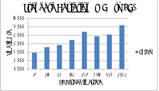
Many programs can be written for the MSP430, hence the size of the programs can differ. Since the bit rate for the TFTP and flash programming is known, we can compute the time required to download and store any sized file. Table 4-3 shows this for different sized files starting from 1 KB to 230 KB (this is the upper bound because a maximum of 229 KB are available in the Flash memory as some of the space is taken by the TFTP boot program). Figure 4-16 shows this data as chart. Note that this table and figure were computed assuming that the time for TFTP and programming the flash is linear increase in the file size.
0 1000 2000 3000 4000 5000 6000 0 1 2 3 Data [in bits]
Time [in seconds]
TFTP process bit rate
27
Table 4-3: TFTP download and flash programming times for different sized files
Boot file size (KB) Processing time (seconds) Boot file size (KB) Processing time (seconds)
1 0.087 205 17.854 5 0.435 210 18.290 10 0.871 215 18.725 15 1.306 220 19.161 20 1.742 225 19.596 25 2.177 230 20.032 30 2.613 35 3.048 40 3.484 45 3.919 50 4.355 55 4.790 60 5.226 65 5.661 70 6.097 75 6.532 80 6.968 85 7.403 90 7.839 95 8.274 100 8.709 105 9.145 110 9.580 115 10.016 120 10.451 125 10.887 130 11.322 135 11.758 140 12.193 145 12.629 150 13.064 155 13.500 160 13.935 165 14.371 170 14.806 175 15.242 180 15.677 185 16.113 190 16.548 195 16.983 200 17.419 205 17.854
28
Figure 4-16: TFTP boot loading processing time as a function of file size
4.3.4 Conclusion
It is logical that the transmission times for different sized UDP payloads are different. The first test consisted of a loop, which creates a new UDP packet and sends it. This obviously requires more time than simply retransmitting a packet that is already in the buffer of the Ethernet controller. These measurements give developers the ability to predict the performance of a UDP application on this platform. The differential measurement (i.e., using the data from the two sets of UDP measurements) enables us to compute the per byte transfer time across the SPI bus, the time to perform a socket open, close, and send a UDP packet. These measurements provide programmers with a good overview of the maximum transmission rates they can expect from this platform.
0 5 10 15 20 25 0 50 100 150 200 250 Time need to
process the file
[in
seconds]
Size of file [in kilobytes]
TFTP boot loading processing time
29
5 Conclusions and future work
This chapter presents conclusions based on the performed tasks and analysis. The initial goals of the project and our achievements are compared. Furthermore, some suggestions are made of future work. Finally, several economic, social, environmental, and ethical reflections are given.
5.1 General conclusions
The main objectives of this project were to fix the TFTP boot loading problem and to evaluate the Microchip TCP/IP stack when using a TI MSP430 MCU and a Microchip ENC28J60 Ethernet controller connected via SPI. The first goal, namely TFTP boot loading now works. The TFTP boot loader program correctly downloads a program into flash memory from a TFTP server. However, some additional improvements could have been made. Since the board has two programmable buttons and one is used for resetting the motherboard. Pressing this button resets the motherboard and downloads an updated version of the file provided by the TFTP server -if there is such a file available on the TFTP server. The second button could have been configured as a soft reset button. When this second button is pushed, the motherboard could simply restart the already loaded program. Unfortunately, I was not able to realize this functionality. A hard reset can be done by simply unplugging and plugging the Ethernet cable. As I had already spent a lot of time to solve the basic boot loading problem I decided not to spend more time introducing this new functionality.
The second goal of this project was to evaluate the Microchip TCP/IP stack’s performance. Several measurements and calculations were done. However, it is possible to do more measurements and calculations. I focused on UDP transmission from the MCU to the PC’s Ethernet controller. Additionally, I calculated how fast a TFTP boot file is processed by the embedded board. In the future, it would be interesting to measure the Transmission Control Protocol (TCP) protocols throughput. Since I was close to the deadline for this project, I decided to skip measurements of TCP.
This was my first experience with hardware, thus I learned a lot about microcontrollers and how to program them. Before this project, my knowledge of the C programming language was very limited. This lead to many struggles when programming the MCU. However, by reading datasheets I gained insight into the MSP430 MCU family. Furthermore, the extensive use of Wireshark motivated me to learn how to use this handy tool much better than I could before this project. Additionally, I inspected every detail of the TFTP protocol and learned how to create UDP packets in the MCU.
If I was to do this project all over again, I would probably start with the IP stack evaluation instead of fixing the TFTP issue. I feel that I could have done a much more extensive evaluation of the IP stack. Unfortunately, I lost a lot of time trying to fix the TFTP problem. However, I would probably not have learned as much as I did about how to program microcontrollers and how the IP stack works at a low level.
My advice to future contributors to this project is to make much more extensive use of the Ethernet controller's buffer when possible. According to my measurements it is possible to decrease the time needed to generate and send UDP packets if one were to make fuller use of the capabilities of this Ethernet controller. Of course, a clear task is to evaluate the TCP module of this IP stack. Additionally, carefully reading the data sheets and documentation can save a lot of time and annoyance.
30
5.2 Future work
As discussed earlier, evaluation of the TCP functionality of the IP stack has not been done, but clearly should be done. Additionally, it is possible to do many interesting calculations based on the existing observations. In this way the capabilities of the motherboard will be much better documented for future developers.
Another area of tests and measurements is to determine the maximum rate at which data contained in UDP packets can be transferred from the PC to the MCU. As the current measurements only consider traffic going in the other direction.
Moreover, the programmable buttons can be used to better effect. It is recommended that both hard and soft reset functionalities be implemented.
A potentially interesting idea is to develop a monitoring program for the network, which uses this embedded platform. A program could monitor a number of these boards to see if they are active or not and to detect failures as soon as possible. A benchmark tool could be implementing to help developers measure and analyze the throughput and latency of different nodes in the network. Furthermore, the TFTP boot loader has an important place in facilitating future tests and measurement. In summary it is it up to future developers to exploit this Swiss knife of a lower power PoE networked computing platform.
5.3 Required reflections
This project reduces costs by exploiting the TFTP boot loading functionality. Future users can develop programs with a code size larger than 16 KB. This can save a developer a lot of money, considering that a node locked single user license of CCS costs US$495.00. This can be a big gain for an organization that needs, for example, to support 50 developers which would otherwise cost US$19,994.00*.
Avoiding these costs raises the question if it is ethical to do this or not. Some people would say that this is ethical because the user does not load program code larger than 16 KB via the IDE. While others might say it is not because the user should pay the company for the use of the IDE. It is up to the user to decide if the usage of TFTPboot loading system is ethical or not. It should also be noted that the TFTPboot loading system can be used with code compiled using other development tools.
While carrying out this project no environmental or sustainability issues were encountered. However, in retrospect the use of the TFTP boot loader does contribute to sustainability as it allows the same hardware to easily be reprogrammed for many different uses – in fact, the same hardware can be potentially dynamically used for different purposes at different times (the maximum number of times that the flash memory can be reprogrammed will set an upper limit on this reuse). Furthermore, this project does not seem to have a positive or negative effect on society, although it facilitates the development of new applications that might have positive or negative effects on society.
31 References
[1] A. López and F. J. Sánchez, “Exploiting Wireless Sensors: A gateway for 868 MHz sensors,” Master’s thesis, KTH Royal Institute of Technology, School of Information and Communication Technology, Stockholm, Sweden, 2012.
[2] “TI MSP430F5437A Datasheet.” . [3] “ENC28J60 Data Sheet.” .
[4] J. Lara Peinado, “Minding the spectrum gaps: First steps toward developing a distributed white space sensor grid for cognitive radios,” Master’s thesis, KTH Royal Institute of Technology, School of Information and Communication Technology, Stockholm, Sweden, 2013.
[5] “SPI Block Guide V03.06.” .
[6] P. M. in D. Mah, “What does the new Power over Ethernet standard mean for IT pros?,” TechRepublic. [Online]. Available: http://www.techrepublic.com/blog/data-center/what-does-the-new-power-over-ethernet-standard-mean-for-it-pros/. [Accessed: 23-May-2014].
[7] “IEEE SA - 802.3af-2003.” [Online]. Available:
http://standards.ieee.org/findstds/standard/802.3af-2003.html. [Accessed: 25-May-2014]. [8] S. Alexander and R. Droms, “DHCP Options and BOOTP Vendor Extensions,” Internet
Request for Comments, vol. RFC 2132 (Draft Standard), Mar. 1997.
[9] J. Alba Tormo Peiró,, “Spectrum sensing based on specialized microcontroller based white space sensors: Measuring spectrum occupancy using a distributed sensor grid,” Master’s thesis, KTH, School of Information and Communication Technology, Communication Systems, Stockholm, Sweden, 2013.
[10] R. Karim and H. Al-Fakhri, “Smart Door Lock : A first prototype of a networked power lock controller with an NFC interface.,” Bachelor’s Thesis, KTH, School of Information and Communication Technology, Communication Systems, Stockholm, Sweden, 2013. [11] R. Droms, “Dynamic Host Configuration Protocol,” Internet Request for Comments, vol.
RFC 2131 (Draft Standard), Mar. 1997.
[12] J. Postel, “Internet Protocol,” Internet Request for Comments, vol. RFC 791 (INTERNET STANDARD), Sep. 1981.
[13] J. Postel, “User Datagram Protocol,” Internet Request for Comments, vol. RFC 768 (INTERNET STANDARD), Aug. 1980.
[14] K. R. Sollins, “TFTP Protocol (revision 2),” Internet Request for Comments, vol. RFC 783, Jun. 1981.
[15] K. R. Sollins, “The TFTP Protocol.” [Online]. Available: http://www.rfc-editor.org/ien/ien133.txt. [Accessed: 23-May-2014].
[16] K. Sollins, “The TFTP Protocol (Revision 2),” Internet Request for Comments, vol. RFC 1350 (INTERNET STANDARD), Jul. 1992.
[17] “TL2575HV-ADJ | Step-Down (Buck) Converter | Converter (Integrated Switch) | Description & parametrics.” [Online]. Available: http://www.ti.com/product/tl2575hv-adj. [Accessed: 23-May-2014].
[18] “TPS2375 | Powered Device | Power Over Ethernet (PoE)/LAN Solutions | Description & parametrics.” [Online]. Available: http://www.ti.com/product/tps2375. [Accessed: 23-May-2014].
[19] “IEEE-SA -IEEE Get 802 Program - 802.3: Ethernet.” [Online]. Available: http://standards.ieee.org/about/get/802/802.3.html. [Accessed: 23-May-2014]. [20] “Introduction to JTAG | Embedded.” [Online]. Available:
http://www.embedded.com/electronics-blogs/beginner-s-corner/4024466/Introduction-to-JTAG. [Accessed: 23-May-2014].
32
[21] “Texas Instruments MSP430 JTAG header pinout.” [Online]. Available: http://www.jtagtest.com/pinouts/msp430. [Accessed: 23-May-2014].
[22] “ProCurve Switch 2626 (J4900B) specifications - HP Products and Services Products.” [Online]. Available: http://h10010.www1.hp.com/wwpc/ca/en/sm/WF06b/12136296-12136298-12136298-12136298-12136316-12136318-31539227.html?dnr=2. [Accessed: 23-May-2014].
[23] “Dell OptiPlex GX620.” [Online]. Available:
http://www.dell.com/support/drivers/us/en/19/Product/optiplex-gx620. [Accessed: 23-May-2014].
[24] “openSUSE.” [Online]. Available: http://en.opensuse.org/Main_Page. [Accessed: 23-May-2014].
[25] “Realtek RTL8139 Ethernet controller.” [Online]. Available:
http://www.realtek.com.tw/products/productsView.aspx?Langid=1&PFid=6&Level=5& Conn=4&ProdID=16. [Accessed: 28-May-2014].
[26] “MSP430 USB Debugging Interface - MSP-FET430UIF - TI Software Folder.” [Online]. Available: http://www.ti.com/tool/msp-fet430uif. [Accessed: 23-May-2014]. [27] “Wireshark · Go Deep.” [Online]. Available: http://www.wireshark.org/. [Accessed:
23-May-2014].
[28] “Tcpdump/Libpcap public repository.” [Online]. Available: http://www.tcpdump.org/. [Accessed: 23-May-2014].
[29] “Eclipse - The Eclipse Foundation open source community website.” [Online]. Available: http://www.eclipse.org/. [Accessed: 23-May-2014].
[30] “CCS - Texas Instruments Wiki.” [Online]. Available:
http://processors.wiki.ti.com/index.php/Download_CCS. [Accessed: 23-May-2014]. [31] “Portal:YaST - openSUSE.” [Online]. Available: http://en.opensuse.org/Portal:YaST.
[Accessed: 23-May-2014].
[32] R. Karim and H. Al-Fakhri, “Smart Door Lock : A first prototype of a networked power lock controller with an NFC interface.,” Bachelor’s Thesis, KTH, School of Information and Communication Technology, Communication Systems, Stockholm, Sweden, 2013. [33] J. L. Peinado, “Mind-the-gaps GitHub,” GitHub. [Online]. Available:
https://github.com/cazulu/mind-the-gaps. [Accessed: 23-May-2014]. [34] “TI-TXT file format -srec_ti_txt Linux man page.” [Online]. Available:
http://linux.die.net/man/5/srec_ti_txt. [Accessed: 23-May-2014].
[35] H. Schlunder, “UDP Performance Test microcontrollers.” [Online]. Available: https://github.com/exosite-garage/mcp_dv102412_cloud. [Accessed: 23-May-2014]. [36] “Microchip TCP/IP Stack Help.” .
33 Appendix A
GitHub repository
All the source code and related documents of this project are publicly available on a GitHub repository. The link to this repository is https://github.com/kekovski/MSP430 and consists of several folders:
¾ Analysis: Calculations and charts based on the measurements ¾ Captures: All the Wireshark captures
¾ The source code is divided in two parts
• Analyze: Program for IP stack evaluation
• Updated version of a TFTP program loader for MSP430 ¾ Figures: All of the used figures in the final report


![Figure 4.3.2 Not transfer interesti resend t result w in the p sending Fig ThMTime [in ms] 4-11: TheoUDP Ponly is thebytes to/fing](https://thumb-eu.123doks.com/thumbv2/5dokorg/5523455.144125/37.892.105.789.105.403/figure-transfer-interesti-resend-sending-thmtime-theoudp-thebytes.webp)


