Report number: 2017:12 ISSN: 2000-0456 Available at www.stralsakerhetsmyndigheten.se
Computational assessment of LOCA
simulation tests on high burnup fuel
rods in Halden and Studsvik
2017:12
SSM 2017:12
SSM perspective
Background
Loss of Coolant Accidents (LOCA) are among the most demanding acci-dents that can happen in a Light Water Reactor (LWR). The lack of cooling and the drop in pressure impose large stresses on the nuclear fuel which would increase the risk of fuel rod damage and the subsequent release of active material. But LOCA is also an accident that the nuclear power plant is designed to withstand with a limited release of radioactivity to the sur-roundings.
Resent research has shown that nuclear fuel that has been irradiated to high burnup can fail at lower temperatures than prescribed by current design criteria. One benign phenomenon is the fragementation of pellets and axial relocation of fuel fragments. Fuel fragments that move within the rod can accumulate at positions where the cladding is strained and cause an increased load there. Models that describes fuel fragmentation and relo-cation and enable analysis including those phenomena has been developed by Quantum Technologies AB and implemented in FRAPTRAN-1.5 (see SSM report 2015:37).
Objective
This report describes the validation of the models against tests performed in Halden and in Studsvik, the latter commissioned by NRC. The objective for SSM in this project is to gain insight into the course of events in a LOCA and how these can be implemented in analytical tools.
Results and conclusion
The comparisons between analysis and tests in this report show good agree-ment and improveagree-ment of the calculations when using the fragagree-mentation and relocation models. The results indicate that without modeling fuel relo-cation there can be a significant underestimation of cladding temperature and local oxidation in case of a cladding damage. This implies that there is a need to include fuel fragmentation in analytical verification of high burnup nuclear fuel in LOCA.
The present work also identifies needs for further development of the ana-lytical tools, for example; failure criteria, fragmentation mechanisms includ-ing constraint from the claddinclud-ing and mechanical effects from fission gases. This development in turn needs further data from tests on nuclear fuel, both for the development and for the validation of the new models.
Project information
Contact person SSM: Anna Alvestav Reference: SSM2015-3357
2017:12
Author:Date: March 2016
Report number: 2017:12 ISSN: 2000-0456 Available at www.stralsakerhetsmyndigheten.se
Lars Olof Jernkvist
Quantum Technologies AB, Uppsala Science Park
Computational assessment of LOCA
simulation tests on high burnup fuel
rods in Halden and Studsvik
SSM 2017:12
This report concerns a study which has been conducted for the Swedish Radiation Safety Authority, SSM. The conclusions and view-points presented in the report are those of the author/authors and do not necessarily coincide with those of the SSM.
Computational assessment of LOCA
simula-tion tests on high burnup fuel rods in Halden
and Studsvik
Report TR15-004, April 15, 2016
Lars Olof Jernkvist
Quantum Technologies AB
I
Contents
Summary ... III Sammanfattning ... IV
1. Introduction ... 1
2. Considered LOCA simulation test ... 5
2.1. The Halden LOCA tests IFA-650.4/9/10/14 ... 5
2.1.1. Design and operation of the IFA-650 test rig ... 5
2.1.2. Test rodlets IFA-650.4, 9 10 and 14 ... 7
2.1.3. Summary of test conditions and test results ... 10
2.2. The NRC-Studsvik LOCA test 192 ... 10
2.2.1. Design and operation of the Studsvik LOCA test rig ... 11
2.2.2. Test rodlet NRC-Studsvik-192 ... 12
2.2.3. Summary of test conditions and test results ... 14
3. Applied methods and computer programs ... 15
3.1. Methodology and computer programs ... 15
3.2. Simulations of pre-irradiation ... 15
3.3. Simulations of LOCA tests ... 16
4. Results and discussion ... 21
4.1. Pre-irradiation ... 21
4.2. Halden IFA-650 LOCA tests ... 22
4.2.1. IFA-650.4 ... 23 4.2.2. IFA-650.9 ... 29 4.2.3. IFA-650.10 ... 35 4.2.4. IFA-650.14 ... 41 4.3. NRC-Studsvik-192 test ... 48 5. Concluding remarks ... 55
5.1. Summary and interpretation of results ... 55
5.2. Transferability of test results to LWR LOCA conditions ... 58
5.3. Suggestions for further work ... 60
5.3.1. Model development ... 60
5.3.2. Computational analyses ... 61
5.3.3. Tests and experiments ... 62
6. References ... 65
II
Appendices
Appendix A:
The Halden IFA-650.4/9/10/14 LOCA tests ... A.1
Appendix B:
The NRC-Studsvik LOCA test 192 ... B.1
Appendix C:
Thermal-hydraulic boundary conditions for Halden IFA-650 LOCA tests ... C.1
Appendix D:
Boundary conditions for the NRC-Studsvik LOCA test 192 ... D.1
III
Summary
In this work, computer analyses are used to assess five recent loss-of-coolant-accident (LOCA) simulation experiments, carried out in Halden, Norway, and Studsvik, Sweden. The experiments were done on short test rodlets that had been sampled from high burnup fuel rods after discharge from commercial light water reactors. The main objectives of the work are to gain understanding of the ther-mal-mechanical behaviour of high burnup fuel under LOCA by making inter-pretations of the test results, to elucidate differences between the Halden and Studsvik experiments with regard to testing conditions, to assess the transferabil-ity of the test results to real light water reactor conditions, and to validate newly developed computational models for high burnup fuel fragmentation and axial relocation that have been implemented in an extended version of the FRAP-TRAN-1.5 computer program.
Key results of the experiments, such as cladding tube temperatures and deforma-tions, are reproduced with fair accuracy in the computer simuladeforma-tions, which indi-cates that most of the involved phenomena are understood and adequately mod-elled. Important exceptions are the fine fragmentation (pulverization) of the high burnup fuel, with associated release of gaseous fission products, and the restricted axial gas flow within the fuel rods.
The newly developed models for axial fuel relocation successfully reproduce the observed relocation and the thermal effects that it brings about by redistributing the fuel rod heat load. Our simulations suggest that axial fuel relocation takes place concurrently with cladding ballooning and that the thermal feedback effects from the relocation are strong enough to affect the dynamics of cladding balloon-ing and rupture. For the simulated Halden tests, the axial fuel relocation increases the calculated peak cladding temperature by 25 to 250 K, and high temperature cladding oxidation is aggravated. These aggravating effects of axial fuel reloca-tion are not seen in the Studsvik tests, since they are done without nuclear heating.
The significance of findings from the experiments as well as the computer analy-ses to the behaviour of full-length fuel rods under conditions expected in light water reactor LOCAs are discussed. Suggestions are also made for future experi-ments, model improvements and further computational analyses.
IV
Sammanfattning
I detta arbete används datorsimuleringar för att utvärdera fem experiment, avsedda att efterlikna haverifall med kylmedelsförlust (LOCA), vilka nyligen utförts i Halden, Norge, och Studsvik, Sverige. Experimenten utfördes på korta provstavar, vilka tagits från använt högutbränt bränsle från kommersiella lättvattenreaktorer. Arbetets huvudsakliga mål är att skapa fördjupad förståelse för det högutbrända bränslets termomekaniska beteende under LOCA genom att tolka provresultaten, att belysa skillnader i provförhållanden mellan Halden och Studsvik, att bedöma provresultatens överförbarhet till verkliga lättvattenreaktor-förhållanden, samt att utvärdera nyligen utvecklade beräkningsmodeller för frag-mentering och axiell omflyttning av högutbränt bränsle. Dessa beräkningsmodel-ler har införts i en utökad version av beräkningsprogrammet FRAPTRAN-1.5. Nyckelresultat från experimenten, såsom kapslingsrörens temperatur och deformation, reproduceras med godtagbar noggrannhet i datorsimuleringarna, vilket antyder att merparten av de aktiva fenomenen är förstådda och nöjaktigt modellerade. Viktiga undantag utgörs av det högutbrända bränslets fina fragmentering (pulverisering), med tillhörande frigörelse av gasformiga fissions-produkter, samt begränsningarna i det axiella gasflödet inuti bränslestavarna. De nyutvecklade modellerna för axiell omflyttning av bränsle reproducerar fram-gångsrikt den observerade bränsleomflyttningen och de effekter på temperaturen som denna ger upphov till genom att omfördela bränslestavens värme-belastningen. Våra simuleringar antyder att axiell bränsleomflyttning sker sam-tidigt med att kapslingsrören sväller upp radiellt, och att de termiska återkopplingseffekterna från bränsleomflyttningen är tillräckligt starka för att påverka kapslingsrörens svällnings- och brottförlopp. För de simulerade Halden-proverna medför den axiella bränsleomflyttningen att de beräknade max-temperaturerna för kapslingen ökar med mellan 25 och 250 K, och att hög-temperaturoxidationen av kapslingen förvärras. Dessa försvårande konsekvenser av axiell bränsleomflyttning saknas i Studsvikproverna, då dessa utförs utan nukleär värmning.
Betydelsen av resultaten, såväl från de beaktade experimenten som från dator-analyserna, diskuteras med avseende på beteendet hos hellånga bränslestavar under förhållanden som kan förväntas i lättvattenreaktorer under LOCA. Förslag ges även för framtida experiment, modellförbättringar och fortsatta datoranalyser.
1
1. Introduction
Loss-of-coolant accidents (LOCAs) in light water reactors (LWRs) may lead to overheating of the fuel rods, which in turn may lead to distension of the internally overpressurized cladding tubes and to loss of cladding ductility by high tempera-ture oxidation of the material. To maintain structural integrity of the fuel and to ensure that the reactor core remains coolable, the cladding temperature and oxida-tion should not transgress certain limits [1]. These regulatory safety criteria for LOCA are based primarily on experimental studies from the 1970s and 1980s, which were carried out on low burnup fuel of the design and materials of that time. The introduction of new fuel designs, most importantly new cladding mate-rials, and the move to higher discharge burnups have prompted a need to verify that the existing safety criteria remain valid and appropriate. To this end, both separate effect tests and integral LOCA simulation tests have been carried out on modern fuel designs and fuel with high burnup over the last decade. Examples of the latter are the IFA-650 series of in-reactor tests in Halden, Norway [2], the out-of-reactor tests done in Studsvik, Sweden [3], and the recent MIR-LOCA in-reactor test in Dimitrovgrad, Russia [4].
One important finding from these tests is that UO2 fuel with a pellet average bur-nup in excess of about 60 MWd(kgU)-1 may ‘pulverize’ into very fine (< 0.2 mm) fragments, when transiently overheated. This kind of very fine fragmentation was not observed in earlier LOCA tests, which were limited to fuel rods with pellet average burnups lower than 35 MWd(kgU)-1. The mechanisms responsible for the pulverization are poorly understood, but the prevailing hypothesis is that it occurs by cracking initiated at overpressurized bubbles and pores that contain gaseous fission products [5]. Hence, a critical overpressure in the pores must be reached for pulverization to occur. This means that the material must be sufficiently heated, and that the heating needs to be fairly fast to preclude stress relaxation by creep and slow gas depressurization through connected pathways or re-solution of gas into the material surrounding the pores. Mechanical constraint from the clad-ding tube, resulting in compressive hydrostatic stress in the fuel pellet, is also known to affect the pulverization [5, 6].
Another conclusion from the aforementioned tests is that the very fine fragments formed by high burnup fuel during LOCA have a higher potential for downward axial relocation within the distending cladding tubes than the fairly large fuel fragments typically observed in early LOCA tests on low to medium burnup fuel. The axial fuel relocation is of safety concern, since it changes the axial distribu-tion of heat load along the fuel rod and also has the potential to increase the amount of fuel material dispersed into the reactor coolant, should the cladding fail [7, 8]. The fuel dispersal is an issue with regard to energetic fuel-coolant interac-tion, radiological consequences and long-term coolability of the material ejected into the coolant [9].
2
The increased propensity for fuel fragmentation, relocation and dispersal at high burnup are probably the most important findings from the recent LOCA simula-tion tests, but some other high burnup effects should also be mensimula-tioned. For ex-ample, the tests show that release of fission product gases from overheated and pulverized high burnup fuel is extensive, and that the axial flow of gas within the fuel rod may be restricted because of pellet-cladding gap closure that occurs at high burnup. The fission gas behaviour in high burnup fuel rods is thus different than in low burnup rods, and the build-up of axial pressure gradients within high burnup rods may amplify cladding ballooning, axial fuel relocation and fuel dis-persal. Another notable high burnup effect is that the oxidation induced embrit-tlement of the cladding under LOCA is aggravated by hydrogen picked up by the metal during the fuel lifetime [10, 11].
The above findings have prompted revisions of LOCA safety criteria in some countries. At the time of writing, new rules have been proposed in France [12] and in the USA [13]. The rules proposed in the USA are performance based and in-tended to expand the applicability of the existing safety criteria from fuel designs with uranium dioxide pellets within cylindrical zirconium alloy cladding tubes to any light-water reactor fuel design or cladding material. Experimental programs are running, e.g. within the OECD Halden Reactor Project and phase three of the Studsvik Cladding Integrity Project (SCIP-III), to gain further understanding and to produce quantitative data on the behaviour of high burnup fuel under loss-of-coolant accidents. The Swedish Radiation Safety Authority (SSM) participates in these projects.
Along with the LOCA experiments on high burnup fuel, computational models and computer programs for analyses of LOCA are being modified and refined to capture the experimentally observed phenomena. An example of international cooperation in this field is the IAEA coordinated research project FUMAC – Fuel Modelling in Accident Conditions. This international project, which is running from 2014 to 2017, brings together 27 organisations, including SSM, with a common interest in improving their computational tools [14]. Organisations par-ticipating in FUMAC are given access to detailed data on experiments deemed particularly valuable for computer program validation. Another benefit from FU-MAC is the possibility to compare models and computational tools used among the participants, and to share knowledge and best practices within the group. A final report on the activities in FUMAC is planned to be issued by the IAEA in 2018. To date, SSM has contributed to the project by developing computational models for axial relocation of fragmented and pulverized fuel pellets in distending fuel rods, including models for the effects on fuel rod heat load that the relocation brings about during LOCA [15-17]. The models have been implemented in an extended version of FRAPTRAN-1.5, a computer program used for fuel rod ther-mal-mechanical analyses of transients and accidents [18].
3
To date, the aforementioned models have been validated against a single LOCA test [15]. The test, Halden IFA-650.4, was done on a fuel rodlet with an average fuel burnup of 92.3 MWd(kgU)-1 that had been sampled from a pressurized water reactor (PWR) fuel rod after seven operating cycles in a commercial power reac-tor. The test resulted in cladding ballooning and burst, as well as significant axial fuel relocation and dispersal of pulverized fuel into the coolant. In this report, we apply our newly developed models for fuel fragmentation, pulverization and axial relocation to four additional LOCA simulation tests on high burnup fuel rods. Three of the tests are in-reactor experiments from the Halden IFA-650 series (tests 9, 10 and 14), whereas the fourth test is an out-of-reactor experiment from the Studsvik series (test 192). Three of these tests, IFA-650.9/10 and NRC-Studsvik-192, belong to the set of experiments considered for model validation in the IAEA coordinated research project FUMAC, which means that all experimen-tal data for these tests have been obtained through this project. It should also be remarked that six other tests in the Halden IFA-650 series have been evaluated by Quantum Technologies in the past [19-21]. These evaluations did not address fuel pulverization or axial relocation. They also differed from the assessment presented here with regard to applied methodology and computer pro-grams.
The primary objective of the work presented in this report is to gain understanding of the thermal-mechanical behaviour of high burnup fuel under LOCA, in particu-lar the axial relocation of fragmented and pulverized fuel and the thermal effects that the relocation may bring about. Another objective is to elucidate differences between the Halden and Studsvik experiments with regard to testing conditions, and how these differences may affect the phenomena observed in the experiments. Understanding of these issues is important, not least for assessing to what extent the experiments are representative of conditions expected in commercial light water reactors under LOCA.
Finally, the work also aims to validate our computational models. The most im-portant computer program used in the assessment, our extended version of FRAPTRAN-1.5, is ultimately intended for safety analyses of LWR fuel under accidents and transients. Validation of the program and its models against experi-ments of the kind dealt with in this report is a necessary step to qualify the pro-gram for such analyses.
The organization of the report is the following:
The LOCA simulation tests in Halden and Studsvik that are assessed in this report are summarized in section 2. Further details on the experimental procedures and the results obtained from the tests and from post-test investigations and analyses are presented in Appendices A and B.
Section 3 deals with the methodology and computer programs that are used for the assessment. In addition to our extended version of FRAPTRAN-1.5, which is used
4
for simulating the actual LOCA tests, we use the FRAPCON-3.5 program for generating the necessary burnup dependent fuel rod initial conditions. No com-puter program is used for calculating the transient thermal-hydraulic boundary conditions that are needed for fuel rod analyses with FRAPTRAN-1.5. These boundary conditions are derived from measured temperatures and pressures in the tests, using assumptions and fitting procedures that are presented in Appendices C and D.
In section 4, we present and discuss the results of our computational assessment in light of measured data from the LOCA tests and from results reported from post-test examinations of the fuel rods. Comparisons are also made with data and re-sults from other LOCA testing programs.
Finally, in section 5, we draw some general conclusions from the presented study and make suggestions for further work. We also discuss the transferability of the results, i.e. the relevance of findings from the experiments as well as the computer analyses to the behaviour of prototypical, full-length, fuel rods under conditions expected in light water reactor loss-of-coolant accidents.
5
2. Considered LOCA simulation test
The LOCA simulation tests considered in our assessment are summarized below. The Halden IFA-650 LOCA tests number 4, 9, 10 and 14 are presented in section 2.1, and section 2.2 deals with the NRC-Studsvik LOCA test number 192. Details on the results of these tests are presented in Appendices A and B.
2.1. The Halden LOCA tests IFA-650.4/9/10/14
The IFA-650 series of tests are conducted since 2003 in the Halden heavy water test reactor, Norway. To date, fifteen tests on short fuel rodlets have been carried out under simulated loss-of-cooling accident conditions. Twelve of the tests have been made on pre-irradiated fuel rods [2, 22]. One of the primary objectives of the tests is to quantify the extent of fuel fragment axial relocation into the ballooned regions of the rods, and to study possible effects of fuel relocation on cladding temperature and oxidation. Several tests have exhibited axial relocation of fuel fragments; the most notable relocation resulted from tests 4 and 9.
2.1.1. Design and operation of the IFA-650 test rig
The design of the IFA-650 test rig is shown in Fig. 1, and a schematic cross-sectional drawing of the heated part of the rig is given in Fig. 2. In each test, a single test rodlet with an active (fuelled) length of 360–480 mm is instrumented and placed in the centre of the rig, which in turn is placed in one of the experi-mental channels of the test reactor. The rodlet is surrounded by an electrically heated shroud and a pressure flask. The heated shroud is part of a flow separator, which separates the coolant into a central channel adjacent to the fuel rod and an outer annulus. The heated shroud provides boundary conditions that resemble the heating effects of nearby fuel rods with similar power. The temperature of the test rodlet is controlled both by nuclear heating of the rodlet itself and the electrical heating of the shroud. The power for the heated shroud is uniformly distributed along the test section, while the axial power profile for the rodlet is peaked to the rodlet midplane; see Fig. 1. The inner/outer diameters of the heated shroud and pressure flask are 20/26.2 mm and 34/40 mm, respectively.
The pressure flask is connected to a water loop. During the precondition phase before the test, the loop is filled with heavy water at a pressure and temperature of about 7 MPa and 515 K, which is circulated by pumps through the loop. Shortly before the test, the pressure flask is isolated from the loop and the test rodlet is cooled only by natural circulation within the flask. The LOCA simulation test is then initiated by opening valves to a blowdown tank, which causes a sudden
6
sure drop in the flask. The coolant flashes to steam, which flows to the blowdown tank and condensates. The flashing lowers the temperature of the remaining cool-ant. At the end of this blowdown phase, the coolant pressure in the flask stabilizes at 0.2–0.3 MPa [22]. The duration of the blowdown phase differs between tests, since some tests are done by evacuating the test rig through flow lines from the bottom part only (referred to as one-sided blowdown), while others are done by evacuating the rig from both the bottom and top (two-sided blowdown). The typi-cal duration of the blowdown phase is 65–70 s for the former case and about 30– 35 s for the latter.
After the blowdown phase, the test rodlet heats up with a rate that depends on the predetermined power levels of the rodlet and the electrically heated shroud. In most of the tests, small amounts of water are periodically sprayed into the up-per part of the rig during this high temup-perature phase to maintain a sufficient amount of steam for cladding oxidation, but otherwise, no actions are taken until the test is terminated by switching off the electrical heater and scramming the re-actor. The test rod is then left to cool down slowly, without quenching, in order to minimize any disturbances that could influence the fuel fragmentation and reloca-tion that may have occurred during the high temperature phase.
Fig. 1: Design of the IFA-650 test rig (left) and rodlet axial power profiles for the four considered test rodlets in the IFA-650 series (right) [22, 23].
7
Fig. 2: Schematic drawing of the heated section of the IFA-650 test rig [20].
The general test procedure includes a preconditioning period of 7–8 hours, during which the test rodlet is operated at a linear heat generation rate (LHGR) around 8.5 kWm-1. The reactor and rod power is decreased prior to the test. During the test, the rod power is held nearly constant, typically at 1–3 kWm-1, depending on the target peak cladding temperature. The axial power profile in the rodlet during the test is nearly symmetric, with an axial peak to average power ratio of 1.04– 1.08. Fig. 1 shows the axial power profiles for the IFA-650 LOCA tests consid-ered in this report. The variation from one test to another is fairly small.
As indicated in Fig. 1, the IFA-650 test rig instrumentation consists of a fuel rod elongation detector, a fuel rod gas pressure transducer, and coolant thermocouples at the inlet and outlet of the rig. For most tests, there are also 2–4 cladding surface thermocouples, three vanadium neutron detectors and 2–3 heater surface thermo-couples. All of these are axially distributed along the rod. Tests 4 and 10 were also equipped with thermocouples at the axial level of the rod gas plenum; the gas plenum is located about 250 mm above the top of the fuel pellet column, away from the heated section.
2.1.2. Test rodlets IFA-650.4, 9 10 and 14
The considered test rodlets were sampled and re-fabricated from full-length light water reactor UO2 fuel rods that had been operated in commercial power reactors to high burnup. All samples were taken from axial segments between spacer grids, except for the IFA-650.14 rodlet. The length of the samples differed, and the ac-tive length of the re-fabricated test rodlets varied between 360 and 480 mm. The design and pre-test material conditions of the considered IFA-650 test rodlets are summarized in Table 1, and the pre-irradiation histories for the re-fabricated short length segments are shown in Fig. 3.
8
Table 1: Design data and pre-test conditions for the considered IFA-650 test rodlets. Data are compiled from [22, 24-29]. It should be remarked that these sources are not always consistent.
Parameter: 650.4 650.9 650.10 650.14
Rodlet active length [ mm ] 480 480 440 360
Cold free volume [ cm3 ] 21.5 19.0 17.0 1.9
Fill gas pressure at 295 K [ MPa ] 4.0 4.0 4.0 2.0
As-fabricated enrichment of 235U [ wt% ] 3.5 3.5 4.49 3.71
As-fabricated fuel pellet density [ kgm-3 ] 10 421 10 443 10 457 10 550
As-fabricated fuel pellet diameter [ mm ] 9.13 9.13 8.19 8.19
As-fabricated fuel pellet height [ mm ] 11.00 (?) 8.00 (?) 13.78 8.70
As-fabricated dish volume per pellet [ mm3 ] 16.0 16.0 11.3 3.8
Pre-test average fuel burnup [ MWd(kgU)-1 ] 92.3 89.9 61.0 70.8
Cladding tube design Duplex Duplex Monotube Liner
Cladding tube base material Zircaloy-4 Zircaloy-4 Zircaloy-4 Zircaloy-2
Inner surface liner material - - - Zr-0.3%Sn
Outer surface liner material Zr-2.6wt%Nb Zr-2.6wt%Nb - -
Heat treatment SRA SRA SRA RX
Inner surface liner thickness (nominal) [ µm ] - - - 70
Outer surface liner thickness (nominal) [ µm ] 100 100 - -
As-fabricated cladding outer diameter [ mm ] 10.75 10.75 9.50 9.62
As-fabricated cladding wall thickness [ mm ] 0.725 0.725 0.570 0.630
Pre-test oxide thickness (mean) [ µm ] 10 7 27 32
Pre-test oxide thickness (max) [ µm ] 11 8 30 40
Pre-test hydrogen concentration [ wppm ] 50 30 150-220 180
Pre-test fast neutron fluence (> 1 MeV) [ m-2 ] 1.52×1026 1.47×1026 1.01×1026 1.18×1026
Fig. 3: Pre-irradiation histories for the considered IFA-650 test rodlets.
9
As part of the re-fabrication process, the test rodlets were filled with a gas mixture consisting of 95 vol% argon and 5 vol% helium to a pressure of either 2 or 4 MPa at room temperature. Argon was used to mimic the low conductivity fission prod-uct gases Xe and Kr, while a small amount of helium was needed to leak test the rodlet. Except for the IFA-650.14 rodlet, the gas plenum volume of each rodlet was made large, in order to maintain a stable internal gas pressure until cladding rupture. The IFA-650.14 rodlet, on the other hand, was fabricated with a very small plenum volume, since this test was intended to be interrupted before clad-ding rupture. The small plenum volume helped to achieve this objective, since it resulted in a declining internal pressure as the cladding tube ballooned.
The test rodlets for IFA-650.4 and IFA-650.9 were re-fabricated from one or two full-length PWR fuel rod(s)1, manufactured by Framatome ANP and operated in the Gösgen nuclear power plant, Switzerland, to very high burnup [24, 25]. The IFA-650.4 rodlet was sampled from the span between the fifth and sixth spacer grid, whereas the IFA-650.9 rodlet was sampled between the second and the third spacer. The active length of both rodlets was 480 mm, and the sampled sections had reached a burnup of 92.3 and 89.9 MWd(kgU)-1, respectively, during seven reactor cycles of operation in the Gösgen reactor. The irradiation histories were very similar, but the IFA-650.4 segment had somewhat higher power than IFA-650.9, as shown in Fig. 3. The mother fuel rod(s) to the IFA-650.4 and 650.9 rodlets had an experimental, Duplex-type Zircaloy-4 stress relieved annealed (SRA) cladding, with an outer layer of Zr-2.6wt%Nb. This cladding had a good corrosion resistance, which explains the low hydrogen concentration and thin ox-ide layer, in spite of the long operating life of the mother fuel rod. The variation in pre-test oxide layer thickness along the rodlets was insignificant.
The mother rod to the IFA-650.10 rodlet was a 17×17 PWR fuel rod of standard Framatome design; it had UO2 fuel pellets with fairly high enrichment and stan-dard stress relieved annealed Zircaloy-4 cladding. The mother rod was irradiated in the Gravelines 5 PWR, France, during five reactor cycles [26, 27]. The average burnup of the sampled fuel rod segment was 61.0 MWd(kgU)-1, and the irradia-tion history is shown in Fig. 3.
The IFA-650.14 rodlet was re-fabricated from a boiling water reactor (BWR) mother rod of SVEA-96 design (AEB072-J9), manufactured by Westinghouse Electric Sweden [29, 30]. The cladding material was recrystallized (RX) Zircaloy-2 with an internal zirconium liner with low concentrations of Sn and Fe. The mother fuel rod was irradiated in the Leibstadt BWR, Switzerland, during seven reactor cycles. The average burnup of the sampled fuel rod segment was 70.8 MWd(kgU)-1, and the irradiation history is shown in Fig. 3. It should be re-marked that the sampled segment contained the fourth spacer grid, and that there were local variations in cladding oxide layer thickness and crud thickness along the part of the segment where the spacer had been positioned [29]. The
1
It is not clear from the available documentation wether the rodlets were sampled from the same mother rod, or from two sibling mother rods in the same fuel assembly.
10
650.14 rodlet differed from the other rodlets also by having a lower fill gas pres-sure and a much smaller fission gas plenum; see Table 1. The plenum was made small to better control the ballooning of the cladding tube and to make it possible to terminate the test before cladding rupture.
2.1.3. Summary of test conditions and test results
The most important test parameters for the considered Halden IFA-650 LOCA tests are summarized in Table 2. All tests resulted in local ballooning of the clad-ding tube, and except for IFA-650.14, the cladclad-ding tube failed. Gamma emission scanning shortly after each test, as well as later neutron radiography of the rodlets, revealed significant axial fuel relocation in all tests except for IFA-650.10. Further details on the tests and results of post-test examinations are presented in Appendix A.
Table 2: Summary of test parameters for the considered IFA-650 tests [24-26, 28].
Parameter: 650.4 650.9 650.10 650.14
Rodlet LHGR [ kWm-1 ] 0.93 2.60 1.37 0.97
Heater LHGR (initial) [ kWm-1 ] 1.5 1.6 1.2 1.5
Peak cladding temperature [ K ] 1075 1475 1114 1065
Blowdown type (one/two sided) 1 2 1 1
Blowdown duration [ s ] 58 35 71 75
Timing of events (after start of blowdown):
Cladding tube failure [ s ] 336 133 249 None
First spraying [ s ] 566 149 (175) 261 None
Reactor scram [ s ] 617 316 417 274
2.2. The NRC-Studsvik LOCA test 192
A series of six out-of-reactor LOCA simulation tests were performed from 2011 to 2012 by Studsvik Nuclear AB, Sweden, under contract with the U.S. Nuclear Regulatory Commission (U.S. NRC). The tests were done on fuel rodlets that had been sampled from full-length mother rods with average rod burnups ranging from 55 to 72 MWd(kgU)-1. All the mother rods were of Westinghouse PWR de-sign and had UO2 fuel pellets and first generation ZIRLO™ (Zr-1.03Nb-0.98Sn by wt%) cladding. The tests were designed to assess the mechanical performance of ballooned and ruptured high burnup fuel rods under typical LWR LOCA condi-tions, and they have provided useful information on fuel fragmentation, axial re-location and dispersal [3, 31].
11
2.2.1. Design and operation of the Studsvik LOCA test rig
The design of the Studsvik LOCA test rig is shown in Fig. 4. A single test rodlet with an active length of about 0.30 m is centred inside a quartz tube and externally heated by infrared radiation from a clamshell furnace. There is no nuclear heating in the tests, and the rig is placed in a hot cell. The rodlet is heated in flowing steam with atmospheric pressure, and the test may be terminated by quenching the rodlet with room temperature water.
Fig. 4: Design of the Studsvik LOCA test rig [32].
A typical test starts at a temperature of 573 K by heating the rodlet such that a nearly constant heating rate of 5 Ks-1 is attained for the cladding tube. The clad-ding temperature is monitored by a single thermocouple, attached by a metal clamp about 50 mm above the axial midplane of the rodlet. The peak cladding temperature ranged from about 1220 to 1430 K for the six tests, and the rodlets were held at the peak temperature for 0, 5, 25 or 85 s to achieve various degrees of oxidation. Following the high temperature hold, two of the tests (189 and 196) were terminated by switching off the furnace and letting the rodlets cool slowly.
12
In the other four tests, the rodlets were first cooled with an average rate of -3 Ks-1 to 1073 K, after which they were quenched by rapidly filling the quartz tube with room temperature water [3, 32].
The test rodlets were filled with helium to pressures between 8.2 and 11.0 MPa at 573 K. These pressures, which are consistent with high-end end-of-life internal pressures in PWR fuel rods, where chosen to induce cladding ballooning and rup-ture with hoop ruprup-ture strains in the range of 30–50 %. Ruprup-ture typically occurred at cladding temperatures around 950–1000 K, i.e. significantly below the peak cladding temperatures reached in the tests.
During the tests, the rod internal pressure was monitored by pressure transducers connected to the top and bottom ends of the rodlet; see Fig. 4. The internal free volume of the pressure lines to the transducers was fairly large; about 7.3 cm3 in the upper end and about 3.1 cm3 in the lower end of the test rodlet. Most of this gas volume remained near room temperature during the tests; see section D.2, Appendix D.
After each LOCA simulation test, the rodlet was subject to a four-point bend test at room temperature to measure the residual mechanical strength and ductility of the ballooned and ruptured region. The two broken halves of the rodlet were then inverted and gently shaken to dislodge loose fuel pellet fragments. Mass meas-urements were made before and after the LOCA simulation test, after the bend test and after the shake test to determine the fuel release at each stage. After the final stage, the size distribution of the dislodged fuel fragments was measured for five of the six rodlets [3, 31].
2.2.2. Test rodlet NRC-Studsvik-192
The rodlet used in the NRC-Studsvik LOCA test 192 was sampled from the mid-dle section of a full-length Westinghouse 17×17 PWR UO2 fuel rod with first generation ZIRLO™ cladding that had been operated to a rod average burnup of 68.2 MWd(kgU)-1 during four reactor cycles at a twin-unit plant in the USA. The first three cycles took place in the first unit from 1987 to 1994 with a two year interruption between the first and second cycle. After the third cycle, the mother fuel rod was extracted from the discharged fuel assembly and inserted into a new assembly, which was operated for an additional reactor cycle in the second unit of the plant from 1999 to 2001. This procedure was applied for altogether ten rods in the original fuel assembly, and some of the sibling high burnup rods have been refabricated into rodlets and used for other tests by Studsvik Nuclear [33, 34]. The design and pre-test material conditions for test rodlet 192 are summa-rized in Table 3, and the pre-irradiation history for the re-fabricated short length segment in the two PWR units is shown in Fig. 5.
13
Table 3: Design data and pre-test conditions for the NRC-Studsvik-192 test rodlet [3, 33-35]. Note that data for the rod design are taken from open literature reports on sibling fuel rods that have been used in earlier tests by Studsvik Nuclear AB.
Parameter: Value:
Rodlet active length [ mm ] 300
Cold free volume [ cm3 ] 10.4
Fill gas pressure at 573 K [ MPa ] 8.2
As-fabricated enrichment of 235U [ wt% ] 3.99
As-fabricated fuel pellet density [ kgm-3 ] 10 440
As-fabricated fuel pellet diameter [ mm ] 8.192
As-fabricated fuel pellet height [ mm ] 9.830
As-fabricated dish volume per pellet [ mm3] 4.2
Pre-test average fuel burnup [ MWd(kgU)-1] 78
Cladding tube design Monotube
Cladding tube material ZIRLO™
Heat treatment SRA
As-fabricated cladding outer diameter [ mm ] 9.500
As-fabricated cladding wall thickness [ mm ] 0.571
Pre-test oxide thickness (mean) [ µm ] 27
Pre-test oxide thickness (max) [ µm ] 30
Pre-test hydrogen concentration [ wppm ] 235
Pre-test fast neutron fluence (> 1 MeV) [ m-2 ] 1.31×1026
Fig. 5: Pre-irradiation history for the NRC-Studsvik-192 LOCA test rodlet [35].
14
2.2.3. Summary of test conditions and test results
The most important test parameters for the NRC-Studsvik LOCA test 192 are summarized in Table 4. Further details on the test and the results of post-test ex-aminations are presented in Appendix B.
Table 4: Summary of test parameters for the NRC-Studsvik LOCA test 192 [3, 35].
Parameter: Value:
Initial temperature [ K ] 574
Initial rod pressure (at 574 K) [ MPa ] 8.21
Cladding temperature at failure [ K ] 981
Peak cladding temperature (PCT) [ K ] 1446
Hold time at PCT [ s ] 5
Steam mass flow [ kgs-1 ] 1.8×10⁻⁴
Timing of events (after start of heating):
Cladding tube failure [ s ] 81
Hold at PCT [ s ] 173-178
Quenching [ s ] 297
15
3. Applied methods and computer programs
3.1. Methodology and computer programsThe computer analyses of the considered Halden IFA-650 and NRC-Studsvik LOCA tests were carried out in two steps. In the first step, the pre-irradiation of each fuel rod segment that was later re-fabricated into a test rodlet was modelled by use of FRAPCON-3.5. More precisely, the pre-irradiation in the relevant nu-clear power plant was modelled with the standard version of the program [36], as delivered by Pacific Northwest National Laboratory (PNNL), without introducing any modifications or extensions to the program. The procedure is described in section 3.2 below.
Calculated results from FRAPCON-3.5, defining the pre-test conditions for each test fuel rodlet, were used as input to the second analysis step. This step involved simulations of the LOCA test with our extended version of FRAPTRAN-1.5. In addition to models for fuel fragmentation, pulverization and axial relocation [15], this version of FRAPTRAN-1.5 also includes a set of models that treat clad-ding high temperature metal-water reactions, solid-solid phase transformation, creep and failure in a unified fashion [37, 38]. The applied version is thus differ-ent from the standard version of FRAPTRAN-1.5 delivered by PNNL [18], and a number of errors observed in the standard version have also been fixed in our ver-sion of the program [39]. Both FRAPCON and FRAPTRAN are best-estimate computational tools, and the presented analyses should be considered as best-estimate; no uncertainty or sensitivity analyses were carried out. However, the analysis of each LOCA test was done twice: with and without the fuel relocation model. Except for this difference, the two calculations were done with identical models and input data.
It should be remarked that no computer program was used for calculating the tran-sient thermal-hydraulic boundary conditions that are needed for fuel rod analyses with FRAPTRAN. These boundary conditions were derived from measured tem-peratures and pressures in the considered test rigs; the applied methodology and assumptions are described in section 3.3 and Appendices C and D.
3.2. Simulations of pre-irradiation
The pre-irradiation of each fuel rod segment that was later re-fabricated into a test rodlet was simulated by use of the standard version of FRAPCON-3.5 [36]. Input for the simulations, in terms of fuel pellet and cladding design data and power histories, are given in sections 2.1.2 and 2.2.2. The linear heat generation rate
16
ing the pre-irradiation was assumed to be uniform along each segment. Nominal core average thermal-hydraulic conditions for each PWR were used in the simula-tions, but the coolant inlet temperature was increased to represent the local condi-tions at the axial elevation pertinent to the considered segment of the full length mother fuel rod.
Recommended default models and options for FRAPCON-3.5 were used in the calculations. In particular, the thin-shell mechanical model was used for the clad-ding tube, rather than the finite element based model. The Duplex-type cladclad-ding material of the IFA-650.4 and IFA-650.9 rodlets was represented by models for M5® cladding, which are available in FRAPCON-3.5 [36]. These models were selected, since the M5® alloy has similar performance with regard to waterside corrosion as the Zr-2.6wt%Nb surface liner in the Duplex cladding.
In all calculations with FRAPCON-3.5, the fuel rod samples were discretized axi-ally into 20 mm long axial nodes. Hence, the number of axial nodes ranged from 15 to 24, depending on the length of the considered sample. The radial discretisa-tion of the fuel pellet stack consisted of 44 annuli.
3.3. Simulations of LOCA tests
The Halden IFA-650 and NRC-Studsvik LOCA tests were simulated with our extended version of FRAPTRAN-1.5, using previously developed high tempera-ture models for the cladding tube [37] in combination with a slightly modified version of the finite element based mechanical solution module [40]. All tests were simulated twice, with and without consideration of axial fuel relo-cation, in order to assess the importance of the relocation to the thermal-mechanical behaviour and high temperature degradation of the tested fuel rodlets. All calculations were done with an axial discretisation consisting of 20 mm long axial segments for the active part of the test rodlet, i.e. the same discretisation as was used for the simulations of the rodlet pre-irradiation with FRAPCON-3.5. Likewise, the radial discretisation comprised 44 annuli in the fuel pellet and one element across the cladding thickness. A constant time step length of 10 ms was used in the calculations, and the simulations covered the heatup phase, the high temperature phase and most part of the cooling phase in each test.
For the Halden IFA-650 tests, the rodlet LHGR was held constant at the values defined in Table 2 until reactor scram, after which the LHGR was reduced to 0.05 kWm-1 to simulate decay heating. The axial power profiles used in the simu-lations of the Halden tests are shown in Fig. 1. No nuclear heating was modelled for the NRC-Studsvik-192 out-of-reactor test.
The NRC-Studsvik-192 test rodlet was filled with helium, whereas the Halden IFA-650 test rodlets were filled with a low-conductivity gas mixture, consisting of
17
95 vol% argon and 5 vol% helium; see sections 2.1.2 and 2.2.2. These gas compo-sitions were postulated for the calculations with FRAPTRAN. In the calculations, the amount of fill gas in each rodlet was adapted, such that the calculated “hot” pre-test pressure matched the measured value for each test.
Other pre-test conditions of the rodlets were defined by the end-of-life fuel rod conditions after operation in the commercial power reactors, as calculated with FRAPCON-3.5. Calculated results for the permanent deformations of fuel and cladding, cladding oxide layer thickness and hydrogen content, as well as the ra-dial distributions of fuel burnup and power, were imported to FRAPTRAN input from FRAPCON output. Most of these data are presented and discussed in section 4.1. It should be remarked that any axial variation in the pre-test conditions calcu-lated by FRAPCON-3.5, such as the cladding oxide layer thickness, was neglected when using them as input to FRAPTRAN.
Transient fission gas release from the high burnup fuel was not considered in the calculations, except for test Halden IFA-650.14. As mentioned in section 2.1.2, this test was performed on a rodlet with an exceptionally small gas plenum vol-ume, which means that the amount of fill gas was much less than the amount of fission gas released during the test. More precisely, there was 1.56×10⁻³ mole fill gas in the rod before the test, and 4.72×10⁻³ mole gas after the test, as a result of transient fission gas release [41]. The amount of gas released during the test corre-sponds to about 18 % of the gas produced during the lifetime of the fuel [41]. For reasons described above, modelling of transient fission gas release was neces-sary for the Halden IFA-650.14 test. The FRAPTRAN-1.5 computer program has no proper model for fission gas release, but the user may prescribe the fractional fission gas release as time dependent input to the program [18]. In our simulations of the IFA-650.14 test, we prescribed the transient fission gas release fraction, xf, by use of a smooth ramp function with respect to time;
s c f t t t t x 1 tanh 2 0.18 ) ( . (1)
Here, t is the time from start of blowdown in the IFA-650.14 test, while tc = 225 s
and ts = 50 s are parameters that were empirically fitted so that the calculated and
measured time histories of rod internal gas pressure matched. Equation (1) is shown graphically in Fig. 30 and will be further discussed in section 4.2.4.
Possible restrictions of rod internal gas flow during the tests were neglected. Hence, the internal gas was assumed to have uniform pressure and composition along the rod, in the rod plena, and in connected gas-containing systems. For the tests in which transient fission gas release was not modelled, the gas composition remained unchanged until cladding rupture was calculated to occur. By default in FRAPTRAN-1.5, steam is assumed to completely and immediately replace the rod internal gas from the time of cladding rupture [18]. Since the inflowing steam has higher thermal conductivity than argon, cladding rupture resulted in improved
18
pellet-to-cladding heat transfer and a rapid rise in cladding temperature along the entire rodlet in our simulations of the Halden IFA-650 tests. This rather unrealistic behaviour is further discussed along with the calculated results in section 4.2. The steam entering the fuel rod after cladding rupture is in FRAPTRAN-1.5 as-sumed to cause oxidation of the cladding inner surface. However, the inner sur-face oxidation is restricted to axial segments that are within a distance of 3 inches from the cladding breach [18].
All the test rodlets considered in this report had internal gas plena that differed from the typical design of LWR fuel rods. The IFA-650 series of rodlets had a single gas plenum that was located about 200 mm above the top of the fuel pellet column, outside the heated zone. The plenum gas temperature therefore remained fairly low during these tests. In the IFA-650.4 and IFA-650.10 tests, thermocou-ples were attached to the cladding and shroud at the axial position of the plenum; see Appendix A. Fig. 6 shows the measured temperatures from the IFA-650.4 test, together with the approximation used for the plenum gas temperature in our simu-lations of the test. During the blowdown phase, the temperature is equal to the saturation temperature of the flashing steam. After blowdown, the gas plenum heats up and approaches a temperature somewhat above the moderator tempera-ture in the Halden reactor (510 K); the temperatempera-ture difference depends on the combined power of the rodlet and heater. The discontinuity of the measured tem-perature histories in Fig. 6 is due to the outflow of hot gas upon cladding rupture.
Fig. 6: Measured temperatures at the gas plenum position for the IFA-650.4 rodlet, together with the approximation for plenum gas temperature used in calculations.
In our simulations of the Halden IFA-650 tests, we used approximations to the plenum gas temperature, similar to the one shown in Fig. 6: For each rod, the gas temperature was assumed to follow the steam saturation temperature during the blowdown phase, which was then followed by a phase with linear heat up to a final gas temperature of 515–535 K. As for the NRC-Studsvik-192 test rodlet, it
19
had a more complex design than the IFA-650 rodlets with regard to internal gas volumes. The modelling of these volumes and their temperature evolution is de-scribed in section D.2 of Appendix D.
The time dependent thermal-hydraulic boundary conditions required by FRAP-TRAN for calculating the fuel rod behaviour during the LOCA simulation tests were derived from temperatures and pressures measured in different parts of the test rigs. The procedure for deriving the boundary conditions for the Halden IFA-650 tests is fairly complex. It is described in detail in Appendix C.
The thermal-hydraulic boundary conditions for the NRC-Studsvik-192 test were simpler, since the test was performed in steam at atmospheric pressure and the heating was by a furnace that surrounded the rodlet. The boundary conditions for this test were derived from the measured cladding temperature close to the mid-plane of the rodlet, in combination with measured data for the typical axial tem-perature variation, obtained during conditioning of the test rig [32]. The thermal boundary conditions applied for the NRC-Studsvik 192 test are de-scribed in detail in section D.1 of Appendix D.
The NRC-Studsvik-192 test rodlet had ZIRLO™ cladding, in contrast to the Hal-den IFA-650 rodlets that had Zircaloy cladding. Since our extended version of FRAPTRAN-1.5 lacks specific material models for ZIRLO™, we used generic Zircaloy models also for the NRC-Studsvik-192 rodlet. More precisely, in all cal-culation presented in this report, we used the Cathcart-Pawel high temperature oxidation model [42], and the Zircaloy-4 high temperature creep model by Ros-inger [43, 44]. The latter was used without any specific creep model for the mixed + phase region.
None of the temperature dependent criteria for cladding high temperature rupture that are available in our version of FRAPTRAN-1.5 [37] worked well for the con-sidered tests. For the IFA-650.4 and IFA-650.9 tests, the calculations resulted in contact between the distending cladding tube and the surrounding heater before cladding rupture was calculated to occur. Once in contact, the heater acted as a die, forcing the cladding balloon to grow in the axial direction until it finally rup-tured. Since this behaviour was not observed in the tests, we postulated an ad-hoc threshold for the effective creep strain, at which the cladding was assumed to fail. This threshold effective strain (logarithmic) was set to 0.75 for the IFA-650.4 and IFA-650.9 tests, since this value resulted in cladding failure just before the clad-ding came into contact with the surrounclad-ding heater; see Fig. 10 and Fig. 16. We adopted the same methodology for the IFA-650.10 and the NRC-Studsvik-192 test, for which the threshold effective strain for cladding failure was set to 0.30 and 0.70 respectively.
The cladding creep rate in FRAPTRAN had to be scaled, in order to match the calculated and measured time to cladding rupture. A scale factor of 0.40 was found to give a good match for the considered Halden IFA-650 tests, when fuel
20
relocation was included in the calculations. To allow meaningful comparisons between tests and also between the calculated cases with and without fuel reloca-tion, this scale factor was used in all calculations presented in this report. Except for the scaled creep rate and the ad-hoc rupture criterion described above, models in our extended version of FRAPTRAN-1.5 were not modified or tuned. The model parameters used in our relocation model were those used in earlier work [15], unless otherwise stated; lp = 0.10 mm, gth = 0.20 mm, gr = 5.0 µm, xr =
0.01, L= 0.69, and S= 0.72.
21
4. Results and discussion
4.1. Pre-irradiationKey results of the simulated pre-irradiation of the considered test rodlets with the FRAPCON-3.5 computer program are summarized in Table 5. Measured data are included for comparison, when available. The calculated cladding corrosion (hy-drogen pickup and oxide layer thickness) is in fair agreement with measurements. We recall from section 3.2 that the non-standard Duplex-type cladding material of the IFA-650.4 and IFA-650.9 rodlets was represented by models for M5® in our calculations with FRAPCON-3.5 [36], in order to reproduce the corrosion per-formance.
Table 5: Pre-test conditions of the test rodlets, calculated with the FRAPCON-3.5 computer program. Measured data are given in brackets for comparison.
Parameter 650.4 650.9 650.10 650.14 192 Rodlet average burnup [ MWd(kgU) -1 ] 91.9 (92.3) 89.5 (89.9) 60.7 (61.0) 70.8 (70.8) 78.4 (78)
Pellet centre burnup [ MWd(kgU)-1 ] 77.9 76.1 54.5 61.6 68.0
Pellet surface burnup [ MWd(kgU)-1 ] 257.0 248.5 128.2 174.6 194.9
Fuel fraction with local BU > 70 MWd(kgU)-1 1.0 1.0 0.11 0.32 0.74
Radial power peaking factor [ - ] 3.53 3.53 3.06 3.34 3.395
Fuel fragment average size [ mm ] 1.87 1.90 2.05 1.93 1.85
Fission gas release [ % ] 11.1 7.6 2.5 3.6 11.1
Cladding hydrogen concentration [ wppm ] 67–76 (50) 57–65 (30) 172–225 (150–220) 415 (180) 213–256 (176–288) Cladding outer oxide
layer thickness [ µm ] 14–16 (6–8) 11–13 (6–8) 20–27 (20–30) 29 (32–35) 22–27 (25–30) Table 5 includes calculated values for the local fuel burnup at the pellet centre and surface (rim). The calculated distribution of fuel burnup is of interest, since it is used in our version of FRAPTRAN-1.5 to estimate the amount of fuel material that may pulverize when overheated during the LOCA test. More precisely, a lo-cal burnup of at least 70 MWd(kgU)-1 is required for the fuel to pulverize, accord-ing to our model [15]. As can be seen from Table 5, the fuel fraction exceedaccord-ing this threshold, and thus susceptible to pulverization at high temperature, ranges from 11 to 100 % among the considered test rods.
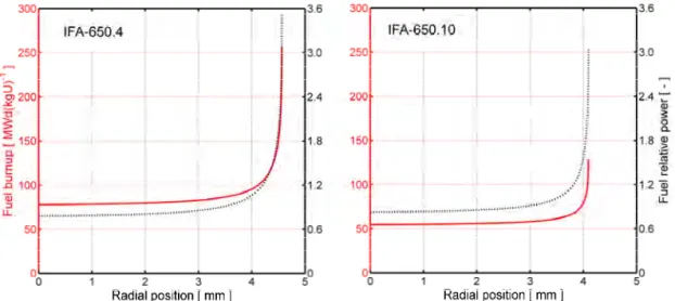
Fig. 7 shows the distributions of power and burnup across the fuel pellets after pre-irradiation of the IFA-650.4 and IFA-650.10 test rodlets, according to our calculations with FRAPCON-3.5. The radial distributions of power are fairly similar in these two test rods, but the distributions of burnup are much different.
22
The calculated distributions are assumed to be valid for the entire length of the test rodlets, since the irradiation conditions were fairly uniform along the sampled rod segments.
Fig. 7: Calculated distributions of burnup (full red line) and power (dashed black line) across the fuel pellets in the IFA-650.4 and IFA-650.10 test rodlets.
The radial distributions of fuel burnup and power, calculated with FRAPCON-3.5, are used in subsequent analyses of the LOCA simulation tests with our extended version of FRAPTRAN-1.5. It is assumed that the distributions do not change with time during the tests – not even when fuel crumbling and axial fuel relo-cation occurs [15].
Finally, from Table 5, we note that the estimated average size of fuel fragments in the considered rodlets range from 1.87 to 2.05 mm before the LOCA tests. These fragment sizes are calculated through an empirical model, based on the fuel pellet average burnup and the peak power experienced by the fuel during its life-time [15].
4.2. Halden IFA-650 LOCA tests
Here, we consider the results of our simulations of the Halden IFA-650 LOCA tests. For each test, calculated results are presented graphically for the cases with and without fuel relocation considered in the analyses with our extended version of FRAPTRAN-1.5. Measured data are included in the graphs for comparison, whenever data are available. Throughout the presentation, time zero refers to the start of the LOCA test, defined by the opening of valves between the in-core pres-sure flask and the blowdown tank; see section 2.1.1.
23
4.2.1. IFA-650.4
Fig. 8 shows the calculated and measured evolution of rod internal gas pressure in the upper plenum during the Halden IFA-650.4 test. From section 3.3, we recall that the gas pressure is calculated on the basis of calculated temperatures and de-formations along the active length of the rodlet, together with a postulated tem-perature history for the gas within the rod plenum. We also recall that the initial cold pressure was reduced from its reported value of 4.0 MPa to 3.86 MPa in our calculations, in order to match the calculated “hot” pre-test gas pressure to the measured value (6.95 MPa). The calculated gas pressure is in close agreement with measurements for t < 290 s, but overestimated for the remaining 46 seconds preceding cladding rupture. A likely explanation to this deviation is that balloon-ing of the claddballoon-ing starts earlier and progresses more gradually than calculated with our version of FRAPTRAN-1.5.
Fig. 8: Calculated evolution of plenum gas pressure in comparison with measurements. Calculations were done with (relo) and without (norelo) assumed axial fuel relocation.
In Fig. 8, the calculated curves for the cases with assumed relocation (“relo”) and without relocation (“norelo”) coincide up to t = 326 s. This is the time at which fuel fragments start to relocate axially, according to our calculations. The calculated time of cladding failure is 334.2 s for the case with fuel relocation and 348.2 s without. These results suggest that cladding ballooning, collapse of the fuel pellet column, and axial relocation of fuel take place in a fairly short (7–8 s) period before cladding rupture, but that the thermal feedback effects are still strong enough to affect the rupture process. For the considered test, the calculated time to rupture was shortened by no less than 14 seconds, as a result of thermal feedback effects from fuel crumbling and relocation. As already mentioned, the deviation between the calculated and measured gas pressure time histories in Fig. 8 suggests that the ballooning and relocation in test IFA-650.4 may actually have
24
occurred over a longer period than in our calculations. If so, the impact of thermal feedback effects on the rupture process would have been even more important. Fig. 9 shows the calculated evolution of cladding deformation and axial fuel relo-cation during the last seven seconds before cladding rupture. The thick red line shows the calculated state at the time of cladding rupture. This is also the state expected after the test is completed, since no further deformation or relocation is supposed to take place after rupture and depressurization of the rodlet. The family of thinner black lines represent the calculated conditions 1, 2, 3,..,7 seconds before cladding rupture. The leftmost curve thus shows the conditions about the time when the balloon starts to grow and fuel starts to relocate.
Fig. 9: Calculated evolution of cladding deformation (left) and fuel relocation (right) during the last seven seconds before cladding rupture. The rightmost curve (red)
represents the conditions at time of rupture, while the seven curves to the left of it show the calculated state 1, 2,...,7 seconds before rupture. A post-test gamma
scan image of the IFA-650.4 test rig is included for comparison [45].
The calculations suggest that the local fuel mass is increased by about a factor of three in the most distended cross section of the test rodlet. The relocated fuel originates from the uppermost, 120 mm long, part of the fuel pellet column, which has disappeared completely. This is well in line with the results reported from the test: Gamma scan (see insert in Fig. 9) as well as ceramography showed that the uppermost part of the fuel pellet column was completely missing after the test; no
25
remaining fuel fragments were detected. The length of the missing fuel part was 190 mm, which is 70 mm longer than calculated with our model. The difference is understandable, since a significant amount2 of fuel had been expelled through the cladding breach and was found just above the balloon and at the bottom of the pressure flask after the test [45]. This dispersal of fuel fragments, which is not accounted for by our model, most certainly increased the amount of fuel lost from the upper part of the fuel rod.
Finally, we note that the calculated fuel temperature is in the range of 1100 to 1159 K, when relocation starts at t = 326 s. This means that, according to our model, the entire fuel column has been pulverized into fine (< 0.2 mm) fragments, and that the crumbled fuel has an assumed packing fraction of 0.72 everywhere in the ballooned region; see the description of the applied models for fuel fragmenta-tion and pulverizafragmenta-tion in [15].
Fig. 10 shows the calculated post-test diameter profile of the IFA-650.4 rodlet in comparison with measurements. The latter were obtained by metallography of thirteen cross sections, for which the cladding tube diameter was measured in two perpendicular directions. Hence, the data also provide some information on the degree of cylindrical symmetry for the deformation. The calculated peak deforma-tion is the same for the two considered cases, since the same failure criterion in terms of a threshold for the local effective strain was used for both of them. How-ever, the calculated deformation profiles differ. As expected, the fuel relocation tends to concentrate, or localize, the cladding deformation. The reason is the con-centrated heat load, resulting from fuel crumbling and accumulation of fuel frag-ments in the ballooned region of the rod.
Fig. 10: Calculated and measured post-test diameter profiles for the IFA-650.4 rodlet [45].
2
The weight of dispersed fuel in the IFA-650 series of tests was not determined. Only qualitative assessments of the dispersal in each test, based on post-test gamma scan results and visual inspections, are available [22, 46].
26
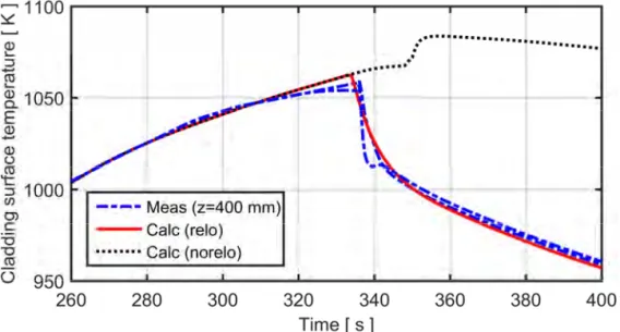
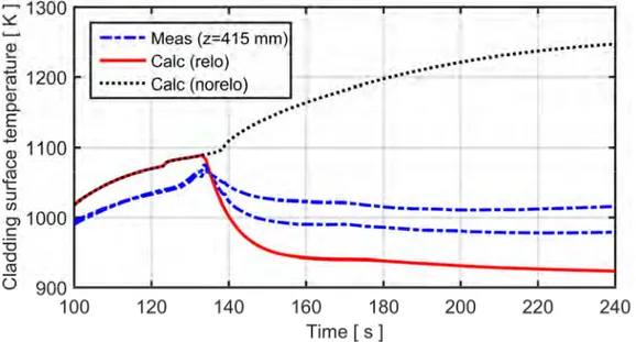
Consequently, we next consider the thermal effects of fuel relocation and their impact on the cladding failure behaviour. Fig. 11 shows a comparison of the cal-culated cladding surface temperature with measured data from thermocouples TCC1 and TCC2, which were located 80 mm below the top of the fuel pellet col-umn, i.e. in the part that was completely emptied of fuel upon cladding rupture; see section A.1, Appendix A. The two thermocouples give very similar results, which suggests that the azimuthal temperature difference along the cladding cir-cumference was insignificant at this axial position. It is clear from Fig. 11 that the cladding temperature is slightly underestimated during the heat-up phase (65 < t < 250 s): the maximum difference between calculated results and measured data is about 20 K. The most likely explanation to the deviation is our simplified model-ling of the clad-to-coolant heat transfer; see Appendix C.
Fig. 11: Calculated and measured cladding surface temperature versus time. The temperature refers to the position of thermocouples TCC1 and TCC2,
400 mm above the bottom of the fuel pellet column; see Table 8.
Fig. 12 is a close-up of Fig. 11, showing the calculated and measured temperature variation about the time of cladding rupture (336 s in experiment, 334 and 348 s in calculations with and without fuel relocation, respectively). The calculated curve for the case with axial fuel relocation is very close to the measured data. This confirms that thermal feedback effects due to the complete fuel loss from the upper part of the rodlet are accurately captured by our model. When the fuel is lost, the cladding temperature approaches that of the surrounding coolant and heater; this is why the calculated and measured curves virtually coincide for t > 345 s.
27
For the calculated case without axial fuel relocation, the cladding temperature increases just after the calculated time of cladding rupture at t = 348 s. The temperature rise is a result of improved pellet-cladding heat transfer, since FRAPTRAN by default models instantaneous and complete ingress of steam from the coolant channel to the pellet-cladding gap upon cladding rupture. The steam has higher thermal conductivity than the initial fill gas, which consisted of 95 vol% argon and 5 vol% helium.
Fig. 12: Calculated and measured cladding surface temperature about the time of cladding rupture (336 s); close-up of Fig. 11.
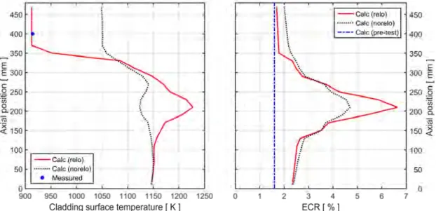
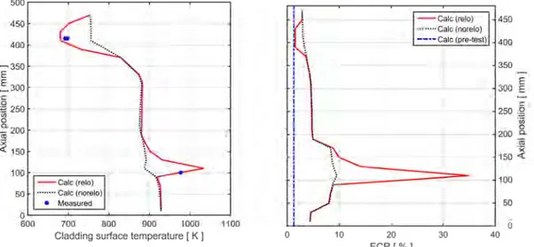
The long term effect of fuel crumbling and axial relocation on the cladding tem-perature and oxidation is illustrated by Fig. 13, which shows the calculated clad-ding outer surface temperature and equivalent cladclad-ding reacted (ECR) versus axial position at time t = 500 s. The ECR is a cladding degradation parameter that is widely used in acceptance criteria for emergency core cooling systems. It is de-fined as the percentage of the cladding thickness that would be oxidized, if all the oxygen from the cladding-water reactions stayed in the oxide layer as ZrO2. At t = 500 s, transient effects from the collapse of the fuel pellet column into the balloon have decayed and the temperature distribution reflects a quasi-steady con-dition. It is obvious that the calculated temperature field for the case with axial fuel relocation is governed by the axial distribution of fuel mass and power; com-pare the right panel of Fig. 9. We note that the case without axial fuel relocation in Fig. 13 shows the opposite trend; the calculated cladding temperature has a mini-mum in the ballooned region, due to the local increase in coolable surface area. It should be remarked that the case calculated without fuel relocation in Fig. 13 is in fact affected by relocation: the low temperature calculated for the upper part of the fuel rod for the case without relocation is due to the decline in heater tempera-ture, which is caused by the fuel relocation that occurs in the test. The measured space-time variation of the heater temperature is used for defining the
28
hydraulic boundary conditions in all calculations with FRAPTRAN, both with and without the relocation model, so this effect is inevitable.
As can be seen from the calculated post-test ECR in the right panel of Fig. 13, the long-term change in temperature distribution caused by the axial fuel relocation has a noticeable effect on the post-failure oxidation of the cladding. The calculated pre-test ECR from low temperature oxidation in Gösgen was about 1.6 %; this pre-test oxidation is included in the curves presented in Fig. 13. From the figure, it is clear that the calculated contribution to the peak post-test ECR from the IFA-650.4 LOCA test is about 70 % larger when axial fuel reloca-tion is considered.
Fig. 13: Calculated cladding outer surface temperature and equivalent cladding reacted (ECR) versus axial position at time t = 500 s,
with and without consideration of axial fuel relocation.
The calculated results presented for the ECR in the right panel of Fig. 13 cannot be directly verified against experimental data, since no post-test measurements were made of the axial variation in cladding oxide thickness or metal oxygen con-centration. However, the outer surface oxide layer thickness was measured at some positions in the ballooned region after the test. It ranged from about 10 to 13 µm, and the thickest oxide was found at the lower end of the balloon [45]. These results indicate that the peak post-test ECR would be around 3.3 %, i.e. significantly lower than our calculated results for the cases with and without fuel relocation. This is not surprising, considering that fuel fragments were ejected from the failed balloon into the coolant during the test. The fuel ejection, which is not accounted for in our simulations of the test, lowered the fuel fragment packing fraction in the balloon. More precisely, the post-test area fraction covered by fuel fragments was estimated to be no more than 0.4–0.5 in the balloon, based on im-age analyses [45]. The low fragment packing fraction that resulted from the fuel ejection most certainly limited the thermal feedback effects of axial fuel reloca-tion in the post-failure part of the experiment.
![Fig. 2: Schematic drawing of the heated section of the IFA-650 test rig [20].](https://thumb-eu.123doks.com/thumbv2/5dokorg/3338213.18433/19.935.236.702.184.385/fig-schematic-drawing-heated-section-ifa-test-rig.webp)
![Fig. 5: Pre-irradiation history for the NRC-Studsvik-192 LOCA test rodlet [35].](https://thumb-eu.123doks.com/thumbv2/5dokorg/3338213.18433/25.935.217.722.732.1039/fig-pre-irradiation-history-nrc-studsvik-loca-rodlet.webp)
![Table 4: Summary of test parameters for the NRC-Studsvik LOCA test 192 [3, 35].](https://thumb-eu.123doks.com/thumbv2/5dokorg/3338213.18433/26.935.301.642.361.635/table-summary-test-parameters-nrc-studsvik-loca-test.webp)
![Fig. 22: Calculated evolution of rod plenum gas pressure in comparison with measurements [26] for the IFA-650.10 test rodlet](https://thumb-eu.123doks.com/thumbv2/5dokorg/3338213.18433/48.935.195.742.245.559/fig-calculated-evolution-plenum-pressure-comparison-measurements-rodlet.webp)
