INTEGRATION OF THERMOCHEMICAL
HEAT STORAGE WITH A MUNICIPAL
DISTRICT HEATING SYSTEM
-In future scenario with large variations in electricity price
MEHDI FARHAMAND GHAFFARPOUR
HENRIK ROS
School of Business, Society and Engineering Course: Degree project energy engineering Course code: ERA401
Credits: 30 hp
Program: Master’s program in sustainable energy systems
Supervisor: Hailong Li Examiner: Valentina Zaccaria Date: 2018-06-11
Email:
mfr16001@student.mdh.se
ABSTRACT
This thesis investigates the feasibility and benefits of integrating Thermochemical heat Storage (THS) into a CHP (Combined Heat and Power) plant. A case study is done for the CHP-plant in Sala, Sweden, with a maximum heat output of 20.9 MW and maximum electricity output of 9.6 MW. The THS type considered is calcium oxide in a hydroxide system. The fluctuations in electricity price for years 2020, 2030 and 2040 are considered and low-price electricity is used as a charging source for THS. During charging the
superheated steam (endothermic reaction) is used to cover some of the district heating demand. The high temperature discharge from the THS is used as reheat in the Rankine cycle. The operations are modeled in Ebsilon and optimization is done in MATLAB using genetic algorithm with the objective to achieve maximum annual revenue. The results suggest that it is not feasible to introduce THS with electricity as a charging source in year 2020, but in 2030 and 2040 THS shows promising potential. The biggest increase in revenue comes from reduced fuel consumption, and, to a lesser extent, increased income from electricity. It is concluded that Calcium hydroxide is a promising candidate for integration into CHP during large electricity price fluctuation. The main drivers for the feasibility of this combination are high fuel price and large fluctuations of electricity price.
Keywords: [CHP, Operation strategies, Energy Storage, Thermochemical Heat Storage, THS, Technoeconomic, Optimization, District Heating, Merit order effect]
PREFACE
This thesis is the final work of our Master studies in sustainable energy systems at
Mälardalens university in Västerås, Sweden. The idea of this project is originated from Jay Hennesy at RISE (Research Institute of Sweden). We would like to say thanks to both Jay Hennesy and our internal supervisor, Hailong Li, associate professor in the department of energy engineering, for their advice and feedback during this project.
During this thesis, Mehdi’s focus was on the latest advancement of thermal energy storage and process design of thermochemical heat storage. Henrik focused on developing the optimization model for CHP-plant with thermal energy storage. The operation strategies are a joint work. There was an energetic cooperation between us to shape this thesis in all stages of this work.
We would like to say thanks to the companies that supported this work with their data, Research Institute of Sweden and Sala-Heby Energi.
Västerås, May 22, 2018
SUMMARY
The focus of this thesis is a conceptual configuration of thermochemical heat storage in combination with Combined Heat and Power(CHP) plants. Utilization of Thermochemical Heat Storage(THS) is simulated through different scenarios in the CHP plant and the model extended for the operation of SHEAB (Sala-Heby Energi AB). SHEAB Supplies the district heating of Sala and Heby municipality, with a total population of about 15 000. The plant consists of a biofuel CHP-plant with 20.9 MW capacity of heating and 9.6 MW electricity production capacity.
The study investigates a pathway of utilization of THS into CHP-plant. The latest advancement in thermochemical heat storage have been studied and due to the characterization of them, calcium oxide in a closed hydroxide system is selected as an alternative for thermochemical heat storage.
The fluctuations in electricity price are considered and electricity is used as charging source for the THS during low electricity price hours. During the endothermic reaction (charging) the high temperature steam is used to provide heat to the DHN (District Heating Network). The current operation of CHP-plant was modeled in Ebsilon and extended to include reheat of the steam, using the high temperature discharge from the THS. Optimization is conducted for years 2020, 2030 and 2040 using genetic algorithm with the objective to find maximum annual revenue.
The results suggest that in 2020 the investment cost of THS is too high for it to be feasible and the fluctuations in electricity price are too small, which means that it is not economical to use electricity as a charging source. The optimized storage size is only 12 MWh but
integrating this storage to the CHP still yield a decreased annual revenue of roughly 5000 EUR/year, compared to the case without THS. In 2030 the THS can be used to better potential, and the optimal size is about 31 MWh. By adding the THS the annual revenue is increased by roughly 25 500 EUR/year. In 2040 the revenue is increased further. By adding a THS of approximately 67 MWh, the annual total revenue is increased by about 68 500
EUR/year, compared to the case without THS. The main factor of the increased revenue is due to decreased fuel consumption and increased income from electricity.
Two sensitivity analyses were done for the year 2030: Increased fuel price and
increased/decreased cost of THS. If the fuel price is increased by 50 % the total increase in annual revenue is roughly 76 000 EUR/year, compared to approximately 25 500 EUR/year in the case with no change in fuel price. With a 50 % decrease in investment cost for THS the increased annual revenue is roughly 44 000 EUR/year, and with a 50 % increase in THS cost, the investment is still profitable, but only by about 14 000 EUR/year. The feasibility of THS is therefore most sensitive to changes in fuel price.
It is concluded that the main drivers to make the combination of CHP and high temperature THS feasible, when using electricity as a charging source, are large fluctuations in electricity price and high fuel price. It is also concluded that Calcium hydroxide is a promising
candidate for integration into CHP to increase the flexibility of the plant during large variations in electricity price.
CONTENT
1 INTRODUCTION ... 1 1.1 Background ... 1 1.1.1 Charging ... 2 1.1.2 DISCHARGING ... 2 1.2 Purpose/Aim ... 3 1.3 Research questions ... 3 1.4 Delimitation ... 3 2 METHOD ... 4 2.1 Literature Study... 4 2.2 Modelling... 4 2.2.1 Controlling factors ... 4 2.2.2 Sensitivity analysis ... 5 3 LITERATURE STUDY ... 63.1 Swedish energy system ... 6
3.2 Sensible heat storage (SHS) ... 7
3.3 Latent heat Storage (Phase-Change Materials) ... 9
3.4 Thermochemical heat storages (THS) ... 12
3.4.1 Ammonia based chemical reaction ... 15
3.4.2 Sulphur trioxide (𝑺𝑶𝟑) dissociation ... 15
3.4.3 Methanol decomposition ... 15
3.4.4 Methane reforming ... 16
3.4.5 Ammonia hydrogen sulfate chemical reaction:... 16
3.4.6 Redox system: ... 17
3.4.7 Reversible chemical reaction of Metal hydroxide ... 18
3.5 Energy storage for CHP ... 19
4 CURRENT STUDY ... 20
4.1 Sala CHP-plant ... 20
4.2.1 Activation of energy storage and high temperature steam utilization during
charging ... 26
4.3 Operational strategies ... 28
4.3.1 Normal operation model ... 29
4.3.2 Normal operation with steam extraction ... 30
4.3.3 Maximized electricity model ... 32
4.3.4 Maximized electricity model with steam extraction ... 33
4.3.5 Heat only model ... 35
4.4 Economic model ... 35
4.4.1 Wholesale electricity price years 2020, 2030 and 2040 ... 35
4.4.2 Cost of biofuel ... 36
4.4.3 Average price of heat for district heating ... 37
4.4.4 Revenue/cost-model ... 37
4.5 Optimization strategies ... 38
4.5.1 CHP-plant without THS optimization strategy ... 38
4.5.2 CHP-plant with high temperature THS optimization strategy... 40
4.5.3 Sensitivity analysis ... 42
5 RESULTS ... 44
5.1 Results and revenue no THS years 2020, 2030 and 2040 ... 47
5.2 Results and revenue with 500°C discharge temperature-THS ... 48
5.2.1 2020 ... 49
5.2.2 2030 ... 50
5.2.3 2040 ... 51
5.3 Sensitivity analysis results ... 52
5.4 Investment evaluation ... 54
6 DISCUSSION... 55
6.1 Thermochemical heat storage ... 55
6.2 Improvements of the model and possible error sources ... 55
6.3 The role of THS in future CHP-plants and energy system ... 57
8 SUGGESTIONS FOR FURTHER WORK... 59
REFERENCES ... 60
APPENDIX 1 [SALA CHP-PLANT OPERATION DURING DIFFERENT DISTRICT HEATING LOADS]
LIST OF FIGURES
Figure 1: Standard heating curve(Fleischer 2015a) ... 10
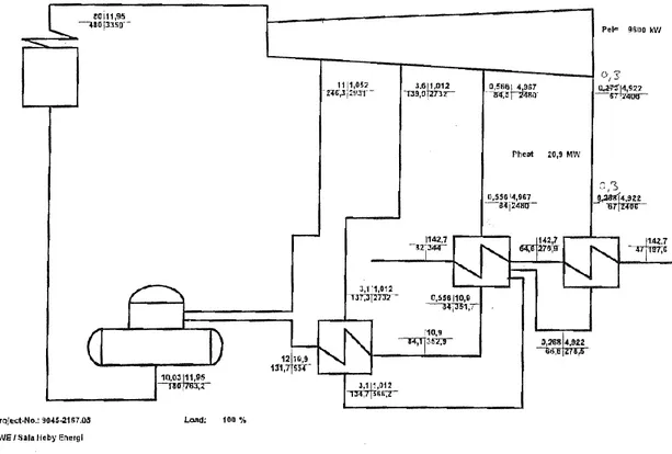
Figure 2 : Boiler at Sala CHP-plant. Captured from reference (Fjärrvärmebyrån AB 1999). . 20
Figure 3: Sala CHP-plant at 100% load ...21
Figure 4 District heating hourly demand Sala 2017...21
Figure 5: Overview of discharging process ... 26
Figure 6: Overview of charging process ... 27
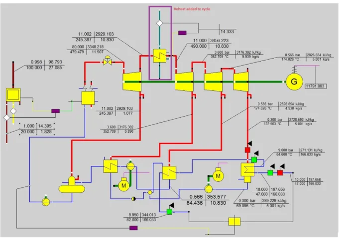
Figure 7: Ebsilon model at district heating demand 20.9 MW ... 29
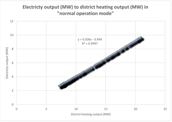
Figure 8: Electricity output (MW) to district heating demand (MW) in normal operation mode ... 30
Figure 9: Electricity output (MW) to district heating demand (MW) in normal operation mode with steam extraction ...31
Figure 10: Ebsilon model with reheat at district heating demand 24.3 MW ... 32
Figure 11: Electricity output (MW) to district heating demand (MW) in maximized electricity operation mode ... 33
Figure 12: Electricity output (MW) to district heating demand (MW) in maximized electricity operation mode with steam extraction ... 34
Figure 13: Average electricity price prediction of hourly basis in 2020, 2030 and 2040 ... 36
Figure 14: General flow chart of operation without THS ... 39
Figure 15: General flow chart of operation with THS ... 41
Figure 16: Revenue with and without THS in years 2020, 2030 and 2040) ... 45
Figure 17: Decreased fuel consumption by adding THS (GWh) ... 45
Figure 18 THS performance in operation, year 2030 ... 46
Figure 19 THS performance in operation, year 2040 ... 46
Figure 20: Operation in 2020 CHP with no THS ... 47
Figure 21: Operation in 2030 CHP with no THS ... 48
Figure 22: Operation in 2040 CHP with no THS... 48
Figure 23: Operation in 2020 CHP with optimal THS ... 49
Figure 24: Operation in 2020 CHP with 50 MWh THS... 49
Figure 25: Operation in 2030 CHP with optimal THS ... 50
Figure 26: Operation in 2020 CHP with 50 MWh THS... 50
Figure 27: Operation in 2040 CHP with optimal THS ... 51
Figure 28: Operation in 2020 CHP with 50 MWh THS ... 51
Figure 29: Revenue sensitivity analysis fuel 2030 ... 52
Figure 30: Fuel sensitivity analysis 2030- Impact of adding THS ... 53
Figure 31: Total revenue sensitivity analysis-cost of THS ... 53
LIST OF TABLES
Table 1: Utilization of exothermic reaction energy ... 2
Table 2: Sensible heat storage advantages and disadvantages ... 9
Table 3 Classification of solid-liquid PCMs ... 10
Table 4: most common PCM applications ... 11
Table 5 Ideal characteristics of TCM adapted from (Yan et al. 2015) ...13
Table 6: Technical development of THS adapted from(Pardo et al. 2014; Garg, Mullick, and Bhargava 1985) ... 14
Table 7 Thermochemical reaction classification with some promising candidate(Yan et al. 2015) ... 14
Table 8: Laboratory experience endothermic reaction of calcium hydroxide decomposition 22 Table 9: THS’ cycle ... 22
Table 10: Charge and discharge rate ... 25
Table 11: 50 MWh THS ... 25
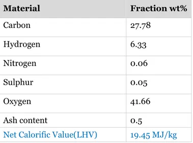
Table 12: Material fractions of the batch used ... 28
Table 13: summary of operations ... 28
Table 14: Functions in normal operation ... 30
Table 15: Functions in normal operation with steam extraction ...31
Table 16: Functions maximized electricity operation ... 33
Table 17: Functions maximized electricity operation with steam extraction ... 34
Table 18: Biofuel price (C_bio) during quarter 2 2016 to quarter 4 2017 (Energimyndigheten 2018b) ... 36
Table 19: The district heating price excluding value added tax from 2018-02-01, converted to EUR with 10 SEK to 1 EUR: ... 37
Table 20: Limits of optimization (no THS) ... 39
Table 21: Limits for high temperature THS optimization strategy ... 40
Table 22: Sensitivity analysis 2030, changed cost of THS ... 43
Table 23: Sensitivity analysis 2030, increased fuel cost ... 43
Table 24: Optimization Results ... 44
Table 25 The optimal Electricity price limit for operation of CHP-plant without THS... 47
Table 26: Optimal optimization limits 2020 with THS ... 49
Table 27: Optimal optimization limits 2030 with THS ... 50
Table 28: Optimal optimization limits 2030 with THS ... 51
LIST OF EQUATIONS
Equation 1 Sensible heat ... 7
Equation 2 Heat of PCM's phase transition ... 10
Equation 3 Heat of PCM's phase transition when Cp is independent to temperature ... 10
Equation 4 Gibbs free energy ...12
Equation 5 Transition temperature of chemical reaction ...13
Equation 6 Heat of exothermic reaction ... 23
Equation 7 Reaction mass balance ... 23
Equation 8 Total required heat rate for endothermic reaction ... 23
Equation 9 Total required heat rate for endothermic reaction ... 23
Equation 10 Exchangeable heat after endothermic reaction (both sensible & latent) ... 23
Equation 11 Sensible exchangeable heat of calcium oxide after endothermic reaction ... 24
Equation 12 Required heat for producing the activation steam for exothermic reaction ... 24
Equation 13 fuel consumption for boiler to cover district heating demand above the capacity of plant ... 32
Equation 14 Required fuel of extra boiler (heat only boiler) ... 35
Equation 15 Total revenue... 37
Equation 16 Annual cost of THS ... 38
NOMENCLATURE
Symbol Description Unit
𝛼 Conversion rate 1 is equal to 100%
CAPes Discharge Capacity of energy storage 𝑀𝑊ℎ 𝐶𝑃𝐻2𝑂(𝑙) Specific heat of water at liquid phase 𝑘𝑗/𝑘𝑔𝑘 𝐶𝑃𝐻2𝑂(𝑔) Specific heat of superheated steam at
constant pressure 𝑘𝑗/𝑘𝑔𝑘
𝐶𝑏𝑖𝑜,𝑦 Cost of biofuel at a certain year 𝐸𝑈𝑅/𝑀𝑊ℎ fuel
𝐶𝑒𝑙,ℎ Cost of low price electricity used to charge the energy storage at a certain hour
𝐸𝑈𝑅/𝑀𝑊ℎ electricity
𝐶𝑒𝑠,𝑦 Cost of energy storage at a certain year 𝐸𝑈𝑅/𝑦𝑒𝑎𝑟
𝐷𝐻𝑑𝑒𝑚𝑎𝑛𝑑 District heating demand 𝑀𝑊ℎ
𝐸𝐿𝑐ℎ𝑎𝑟𝑔𝑒−𝑙𝑖𝑚𝑖𝑡 Electricity price limit for the plant to charge the THS with low price electricity
Symbol Description Unit 𝐸𝐿𝑑𝑖𝑠𝑐ℎ𝑎𝑟𝑔𝑒−𝑙𝑖𝑚𝑖𝑡 Electricity price limit for the plant to
discharge the THS 𝐸𝑈𝑅/𝑀𝑊ℎ
𝐸𝐿𝑙𝑖𝑚𝑖𝑡 Electricity price limit for the plant to
generate electricity 𝐸𝑈𝑅/𝑀𝑊ℎ
𝐸𝐿𝑝𝑟𝑖𝑐𝑒 Electricity price 𝐸𝑈𝑅/𝑀𝑊ℎ
𝐼𝐶𝑒𝑙,ℎ Income of selling electricity at a certain
our (h) 𝐸𝑈𝑅/𝑀𝑊ℎ
𝐼𝐶𝑑ℎ,ℎ Income from selling heat to the district
heating network at a certain hour 𝐸𝑈𝑅/𝑀𝑊ℎ
𝐼𝑛𝑣𝑒𝑠 Investment cost of energy storage 𝐸𝑈𝑅
𝐺 Gibbs free energy 𝑘𝑗/𝐾
∆𝐻𝐶𝐴(𝑂𝐻)2𝐸𝑛 Required Sensible heat rate, calcium
hydroxide during endothermic reaction 𝑘𝑗/𝑚𝑜𝑙 ∆𝐻𝑟𝐸𝑛 Required heat rate during the
endothermic chemical reaction 𝑘𝑗/𝑚𝑜𝑙 ∆𝐻𝐶𝑎𝑂𝐸𝑛 Exchangeable heat rate of calcium
oxide after endothermic reaction(sensible)
𝑘𝑗/𝑚𝑜𝑙
∆𝐻𝐻2𝑜𝐸𝑛 Exchangeable heat rate of steam after
endothermic reaction(latent+sensible) 𝑘𝑗/𝑚𝑜𝑙 ∆𝐻𝐻2𝑜𝐸𝑥 Required heat rate for producing the
activation steam(Latent+sensible) 𝑘𝑗/𝑚𝑜𝑙 ∆𝐻𝑟𝐸𝑥 Released heat rate during exothermic
chemical reaction 𝑘𝑗/𝑚𝑜𝑙
∆𝐻𝐸𝑛 Total heat rate required for
endothermic reaction (∆𝐻𝐶𝐴(𝑂𝐻)2𝐸𝑛+
∆𝐻𝑟𝐸𝑛)
𝑘𝑗/𝑚𝑜𝑙
∆𝐻𝑣𝑎𝑝𝑜𝑟𝑖𝑧𝑎𝑡𝑖𝑜𝑛 Enthalpy of vaporization for water 𝑘𝑗/𝑘𝑔
𝐿𝐻𝑉 Net caloric value 𝑀𝐽/𝑘𝑔
𝐿𝐿ℎ𝑒𝑎𝑡 Lower heat output limit for the plant to
generate electricity 𝑀𝑊
𝐿𝐿𝑒𝑠−ℎ𝑒𝑎𝑡 Lower heat output limit for the plant
with reheat to generate electricity MW 𝑚𝐶𝐴(𝑂𝐻)2 Total mass of calcium hydroxide 𝑘𝑔
𝑚𝐶𝑎𝑂 Total mass of calcium oxide 𝑘𝑔
𝑚𝐻2𝑂 Total mass of water, water content of
calcium hydroxide 𝑘𝑔
𝑚̇𝑏𝑖𝑜 Mass flow of biofuel 𝑘𝑔/ℎ
𝑛 Expected life time 𝑦𝑒𝑎𝑟𝑠
Symbol Description Unit
𝑁𝑃𝑉𝑒𝑠 Net present value of energy storage 𝐸𝑈𝑅
𝑇∗ Reaction transition temperature at the
constant standard pressure 𝐾
𝑇𝑏𝑜𝑖𝑙𝑖𝑛𝑔𝐻2𝑂 Boiling temperature of water 𝐶𝑒𝑙𝑠𝑖𝑢𝑠
𝑇𝐷.𝐻 District heating temperature that THS
exchange heat with 𝐶𝑒𝑙𝑠𝑖𝑢𝑠
𝑇𝐻2𝑂(𝑔) Temperature of superheated steam 𝐶𝑒𝑙𝑠𝑖𝑢𝑠 𝑄𝑟𝐸𝑥 Released heat of exothermic chemical
reaction 𝑀𝑊ℎ
𝑄𝑟𝐸𝑛 Total required heat for endothermic
reaction 𝑀𝑊ℎ
𝑄𝐻2𝑂𝐸𝑛 Total Exchangeable heat of steam after
endothermic reaction 𝑀𝑊ℎ
𝑄𝐶𝑎𝑂𝐸𝑛 Total Exchangeable heat of calcium
oxide after endothermic reaction 𝑀𝑊ℎ 𝑄𝐻2𝑂𝐸𝑥 Total required heat to supply the
activation steam for exothermic reaction
𝑀𝑊ℎ
𝑄𝑎𝑓𝑡𝑒𝑟𝑅𝐻 Energy content in stream after
reheating the Rankine cycle 𝑀𝑊ℎ
𝑄𝑎𝑐𝑡𝑖𝑣𝑎𝑡𝑖𝑜𝑛,𝑒𝑙,𝑒𝑠, Total electrical energy required for activating the discharge process of the THS
MWh
𝑄𝑏𝑖𝑜 Energy content in biofuel MWh
𝑄𝑐ℎ𝑎𝑟𝑔𝑒,𝑒𝑙,𝑒𝑠,ℎ Energy content in electricity used to charge the energy storage at a certain hour
MWh
𝑄𝑑𝑖𝑠𝑐ℎ𝑎𝑟𝑔𝑒 Energy content in stream to reheat
(from energy storage) MWh
𝑄𝐷.𝐻 District heating demand MWh
𝑄𝐷.𝐻 𝑛𝑒𝑤 New district heating demand, after
utilizing excess heat during charging THS
MWh
𝑄𝑒𝑙,ℎ Electricity sold to the grid at a certain
hour MWh
𝑄𝑒𝑠 Energy content in energy storage MWh
𝑄𝐸𝑆𝑜𝑢𝑡𝑝𝑢𝑡 Required discharge from energy
storage MWh
𝑄ℎ𝑒𝑎𝑡−𝑜𝑛𝑙𝑦 Heat output from heat-only boiler MWh
𝑄𝑓𝑢𝑒𝑙,ℎ𝑒𝑎𝑡−𝑜𝑛𝑙𝑦 Energy content in fuel for heat-only
Symbol Description Unit 𝑄𝑟𝑒𝑡𝑢𝑟𝑛 Energy content in steam returning to
energy storage during discharge MWh
𝑟 Annual interest rate %
𝑅2 Residual
𝑅𝑦 Revenue at a certain year (y) EUR
𝑆° 𝑟𝑥𝑛
𝑈𝐿ℎ𝑒𝑎𝑡 Upper heat output limit for the plant to generate electricity without steam extraction
MW
𝑈𝐿𝐸𝑆−ℎ𝑒𝑎𝑡 Upper heat output limit for the plant with reheat to generate electricity without steam extraction
MW
𝑈𝐿𝑠𝑡𝑒𝑎𝑚𝑒𝑥𝑡𝑟𝑎𝑐𝑡 Upper heat output limit for the plant to generate electricity with steam
extraction
MW
𝑈𝐿𝐸𝑆−𝑠𝑡𝑒𝑎𝑚𝑒𝑥𝑡𝑟𝑎𝑐𝑡 Upper heat output limit for the plant with reheat to generate electricity with steam extraction
MW
ABBREVIATIONS
Abbreviation Description
ATES Aquifer Thermal Energy Storage BTES Borehole Thermal Energy Storage
CHP Combined Heat and Power
CSP Concentrated Solar Power
DH District Heating
DHN District Heating Network
LHS Latent Heat Storage
PCM Phase Change Material
PTES Pit Thermal Energy Storage
SHS Sensible Heat Storage
STPP Solar thermal power plant
TES Thermal Energy Storage
Abbreviation Description
TTES Tank Thermal Energy Storage
TCM Thermochemical material
IRR Internal rate of return
MIRR Modified internal rate of return
NPV Net present value
PB Payback time of investment
DEFINITIONS
Definition Description
𝐶𝐻𝐼𝑟+𝑠
Charge input both sensible & reaction CA(OH)2(25°c) → CA(OH)2(510°c)
CA(OH)2(510°c) →H2O(510°c) +CaO(510°c)
𝐶𝐻𝑂𝑉
Charge output
H2O(510°c) → H2O(25°c) CHOCA Charge output sensible
CaO(510°c) → CaO(25°c) 𝐷𝐶𝐻𝑂𝑟 Discharge output
H2O(250°c) +CaO(25°c) → CA(OH)2
𝐷𝐶𝐻𝐼𝑉
Discharge input H2O p=2bar H2O(25°c) → H2O(250°c)
RIP(MWh) Induction power for 1 reactor
RM(kg) Mass of CA(OH)2 in 1 reactor
ES(MWh) Energy storage RS(kg/h) Reaction size
HES(MWh) Hourly Energy storage CHL(MWh) Charging limit
HRS(kg/h) Hourly reaction sized
RT(°C) Temperature of CA(OH)2 in 1 reactor
1
INTRODUCTION
1.1 Background
The international energy agency reported an increasing trend of sharing the renewable energy in European union. In annual report of world energy outlook year 2017, it is predicted that 80% of the total energy will be supplied with renewable energy in 2040. After 2030, the wind power will be the major source of electricity due to the constant development of wind power both offshore and onshore(WEO 2017). Growth of renewable energy sources is the major driver of high merit-order effect of renewable energy in the future. In addition, lower marginal costs of renewable energy, in comparison with conventional power plants also results in a higher merit order effect of renewable energy. Consequently, the revenue of conventional power plants will be affected by merit-order effect(Deane et al. 2017). The daily, weekly and monthly variation of energy demands in the residential, industrial, commercial and utility sectors can be fulfilled with help of a synergic operation of Thermal Energy Storage (TES) (Dincer and Rosen 2010).
In the future, the electricity spot price will have higher variation, and lower price with response to the demand. A CHP-plant without energy storage is limited to the configuration of the plant and thus it’s maximum heat and power generation. With the addition of an energy storage, further operation strategies by charging and discharging the storage for increasing heat and power production in the plant may be developed.
The fundamental principal of thermal energy storage is by process of cooling, heating, melting, solidifying, or vaporizing a material. By reversing these processes, the energy is available as heat and the energy storage system works with these reversible processes. There are mainly three types of TES. Sensible heat TES that takes place by heating and temperature rise. Latent heat TES by melting or vaporization (or solidifying or liquefying). TES that is in the form of a chemical reaction is thermochemical TES. In all of these types of thermal energy storage, energy recovers in form of heating or cooling by reversing the process(Dincer and Rosen 2010).
TES has different applications, mostly in heating and cooling. The state of the art for TES is mostly based on the molten salt technology, as the Phase change material(PCM), because of the domination of sensible and latent heat. PCMs with higher energy density than sensible TES, are characterized by low to moderate energy densities (0.2, -0.5𝑚𝐺𝐽3). The main challenge in utilization of PCM appears in large scale TES, with significantly high heat losses. The solution for overcoming this challenge is thermochemical heat storage (THS). This
technology offers a high energy storage density (0.5 to 3𝑚𝐺𝐽3). Heat losses are also lower which enable the potential of large scale, long time storage capacity.(Sakellariou et al. 2015).
In this study, a promising thermochemical material(TCM) is investigated as THS. The performance of THS integrated with CHP-plant is studied and the following applications for charging and discharging the storage are considered. These applications are explained in further detail under section 4.24.
1.1.1 Charging
During low electricity price situations, it may be beneficial to use electricity as a heat source for the energy storage or district heating system. In (Schweiger et al. 2017), it is concluded that the potential of power to heat in Swedish district heating systems amounts to 0.2-8.6 TWh with the assumption of applying electric boilers as power to heat technology. It is also concluded that by adding TES, the potential for power to heat is increased further.
In this thesis, for charging the THS, only charging with low price electricity is considered due to the high temperature heat requirement for charging. the hourly variations in electricity price prediction in years 2020,2030,2040 is considered as electricity price. THS is charged during hours that electricity price is optimal. Other charging possibilities with different THS are discussed in the discussion part of the report.
During charging the THS, the superheated steam as the product of the decomposition of the selected TCM, is also utilized to the DHN. Therefore, it covers a part of the heat demand of the DHN. More details are available in the section 4.2.1.
During charging, the other product of decomposition, is solid calcium oxide at temperature of 510°C. The heat content of calcium oxide after decomposition is considered as loss. More details are available in the section 4.2.
1.1.2 DISCHARGING
The heat from the THS may be used in several ways in the CHP plant. In this study, in the Table 1, these utilization pathways are considered.
Table 1: Utilization of exothermic reaction energy
utilization of the exothermic reaction’s energy in the form of heat during discharge
❖ Reheating the steam in Rankine cycle ❖ Exchanging the available heat directly with DHN
Depending on the discharge temperature of the THS, the discharged heat may be used for reheating the steam after the high-pressure turbine. More details are available in the sections 4.3.3 & 4.3.4. By doing this, the electrical efficiency of the CHP-plant can be increased at the same time, the overall efficiency of the plant might increase as well.
The discharged heat also can be utilized as heat to the district heating system during high demand situations or as a complement to the boiler during low electricity price hours. By doing this, the plant fuel consumption can be reduced.
1.2 Purpose/Aim
In this work the feasibility of integrating THS with low price electricity as the charging source into the CHP-plant is investigated. The aim is to do a process design of a suitable THS,
develop more flexible operational strategies to maximize the revenue, find optimal operation and optimal THS capacity in future scenarios with different variations in electricity price.
1.3 Research questions
• What are the major drivers for implementing THS into the CHP-plant?
• What is the optimal operation of a common Swedish steam Rankine cycle integrated with high temperature THS when electricity is used as a charging source?
• What are the promising candidates of THS when integrating it to CHP-plant?
1.4 Delimitation
Assumptions have been made in simulation, including the construction of the operational strategies, THS process design and THS operation in CHP-plant. In section 4, Current study, all assumptions are described in further details for the related area of study. Significant limitations for the simulation purposes, are described as follow:
❖ This work is limited to current predictions of the hourly electricity price that always has some uncertainties.
❖ The thermochemical material and technology studied in this study is assumed to be in an ideal form that is ready for commercial application.
❖ The plant configuration limits the operation-flexibility of the CHP-plant.
❖ The plant has a sensible heat storage (tank). For simplification, this storage is not modelled. Instead a separate biofuel boiler is simulated to cover the excess heat demand above the capacity of the main boiler.
❖ Maintenance costs of the plant were not available. The maintenance costs of the CHP-plant are assumed to be the same with or without THS.
❖ The district heating demand is assumed to remain constant in years 2017, 2020, 2030 and 2040.
❖ Shifting the operation strategy in hourly basis, may have some limitation in the real CHP-plant. In this study, it is assumed that it is possible to change the operation strategy hourly. ❖ The conversion rate of chemical reaction is assumed to be full conversion.
2
METHOD
In this section, the methodology is described and divided into parts: Literature study and modelling. Modelling is described in further detail under section 4, Current study.
2.1 Literature Study
Previous research has been studied in a literature study. Areas studied include CHP-plants, Energy systems, Electricity price predictions, Energy storage technologies, and complex systems with energy storage applied to different technologies. Research papers have been gathered from databases Google Scholar, Science Direct and IEEE. Other references were gathered from home pages, Google search and through Mälardalen University.
2.2 Modelling
The current operation of Sala CHP-plant, but excluding the SHS, is modeled in Ebsilon professional at different district heating loads. Steam-bypass over the turbine for utilization directly to the DHN is modeled to increase maximum heat production. The model is
extended by adding a heat exchanger for reheat of the steam in the Rankine cycle, the energy for reheat is the high temperature discharge from the THS. Based on the heat exchanger performance in the Ebsilon model, a conceptual process design of the THS is done in the section 4.2, to determine the required process values of THS. For simplification, the
electricity production, fuel consumption, discharge from the THS, and steam extraction have been correlated as functions of heat demand. Different operational strategies are constructed in the section 4.3, by considering the limitation of the plant and more flexible operations with THS.
An economic model is developed with the objective to optimize the operation of the plant to achieve the maximum annual revenue. In the section 4.5, different strategies for optimization are described. Optimization is done using single objective genetic algorithm to determine the optimal performance of the CHP-plant using the described strategies. Optimization is
performed over an 8736-hour year. Optimization includes these information: which operation strategy is optimal strategy at a certain hour, charge or discharge of THS at a certain hour, optimal THS capacity that leads to highest revenue.
Excel is used for the data handling and curve fitting. MATLAB is used for optimization.
2.2.1 Controlling factors
The DHN is controlling the heat demand and thus the cooling capacity of the condenser in the CHP-plant. The heat demand from the DHN must always be fulfilled and the plant shall
never generate more heat than is needed for district heating demand. The electricity power output of the plant is dependent on the electricity price and DHN heat load. Furthermore, the charge and discharge of the THS is considered for supplying the DHN with heat during periods of low electricity price and high heat demand. Fuel price and district heating prices are also considered for optimization purposes.
2.2.2 Sensitivity analysis
Since the THS technology chosen is still novel, the investment for the THS will be estimated for different investment costs to determine the maximum investment cost to make the addition of THS worthwhile. A sensitivity analysis will also be done for fuel price.
3
LITERATURE STUDY
The literature study focuses on the Swedish energy system and different ways of storing thermal energy. The aim is to find a promising TES-candidates for use in the CHP-plant in the future Swedish energy system.
3.1 Swedish energy system
In 2017, electricity in the Swedish energy system was generated by 40% nuclear power, 40% hydropower, 11% wind power, and 9% power from heat and power plants (mainly biomass). The total electricity production was 159 TWh. The energy consumption in 2017 is more or less at the same level as for 15 years ago (Energimyndigheten 2018a).Today the Swedish electricity production is almost fossil free thanks to high penetration of nuclear and hydro power.
The Swedish nuclear reactors Ringhals 1 and 2 are to be closed down in 2019-2020
(Vattenfall 2017) and Oskarshamn 1 is expected to be closed down before 2020 (Bixia 2015). Even though the decision has been made that new reactors may be built, it takes many years to build them. Today the Swedish energy system is dependent on nuclear power for base electricity production. The transformation of nuclear power energy to renewable energy in the future may cause intermittent production of electricity which results in some challenges between production and demand.
(Karin Byman, Koebe, and Ingenjörsvetenskapsakademien 2016) investigated different pathways the Swedish electricity may be produced up to 2030 and 2050 to remain fossil free. The first of four pathways are more solar and wind-power. In this case the wind and solar power is increased, and up to 70 TWh of electricity is to be generated from wind power, and 20 TWh is to be generated from solar power annually. This case is seen as the case with most challenges in the future, because the electricity production is intermittent. The grids must be extended internally, but also between countries with high penetration of solar and wind power. It is stated that high volumes of over-and underproduction may occur locally.
The second case is with more electricity from biofuels. Here about 40 to 60 TWh of electricity shall be generated from biofuels annually. Wind power is also extended to 30-50 TWh and solar power to 5 TWh. It is stated that for this case to work, the CHP-plants must have a better collation between electricity and heat markets, and that new means of cooling the steam-cycle should be investigated, so more electricity can be produced when needed. The last two cases are new nuclear power and extended hydro power. In the case with new nuclear power, the mix for producing electricity is similar to today, but the nuclear reactors are replaced with new ones, wind power is extended to about 20 TWh and solar power to about 5 TWh. In the case with extended hydro power, hydro power is built in the rivers that are protected by environmental restrictions today. The bio power is also extended to 30-40TWh. This case is seen as the most flexible since hydro power can react to the demand, however over capacity in northern Sweden may occur.
Various sources state the electricity price is predicted to increase in the future. The company Bixia has done a long-term prediction of the electricity price which states that the electricity prices will decrease until 2019, but then increase to an average price of 37 EUR/MWh in 2030, compared to about 27 EUR/MWh in 2016. They also predict larger variations of electricity prices during the day, mostly since the wind power is increased. Even today, signs that the wind power decreases the electricity price during windy weather have been observed (Bixia 2017). Profu draw similar conclusions in the report (Profu 2010), where the production electricity price is expected to increase by almost 30% in 2030, compared to today’s prices. Svenska kraftnät predicts that when the electricity production from nuclear power decrease, uncertainties of the electricity price arise. They predict that the purchasing price of electricity from wind and hydro power increase to roughly 42-47 EUR/MWh in 2030 in areas SE2 and SE3 (Hilda Dahlsten 2017).
The fuel for the CHP-plant is mostly biomass that is locally available. Today, a total demand for forest-based biomass for energy purposes is 130 TWh annually, and it is expected to increase by 30TWh in 2030 and 35-40 TWh in 2050 (Börjesson, Hansson, and Berndes 2017). The effective use of biomass for both power and heat-production means significant reductions in CO2-emissions, compared to the use of Natural Gas or other fossil fuels and can therefore be an important part of a sustainable energy system. In Europe, only a small part of the heat in CHP-plants is generated by renewable resources. The main fuels for CHP-plants in Europe are natural gas and coal resources (Werner 2017).
The district heating plants are usually equipped with short term sensible energy storage (hot water tanks) to enhance the operation flexibility of the plant. The district heating
network(DHN) itself may also be used as energy buffer, by increasing the temperature in the DHN during low demand. An advantage of using the DHN as an energy buffer is that no additional investments must be made, on the other hand the overall heat losses are increased (Sartor and Dewallef 2018).
3.2 Sensible heat storage (SHS)
Sensible heat storage’s(SHS) principle is with raising the temperature of storage material and increasing the internal energy during charging process(Eslami and Bahrami 2017). SHS are bulkier and mainly based on the weight, heat capacity(Dinker, Agarwal, and Agarwal 2017). SHS is the most developed and applied type of thermal energy storage. There is no phase change occurrence in SHS material and this system applies the temperature difference to a medium to store energy.(Scapino et al. 2017). SHS’ main components are a storage medium, a container, connection and nozzles as the inlet and outlet. Because of the potential of heat losses, SHS container usually equipped with thermal insulation. The SHS potential can be expressed by Equation 1 (Zhang et al. 2016):
Equation 1 Sensible heat
𝑄 = 𝑚 ∫ 𝐶𝑇𝐻 𝑃
𝑇𝐿
𝐶𝑃 is specific heat of storage material at constant pressure. The mass of storage material is 𝑚. The high and low temperatures of SHS application are 𝑇𝐻 & 𝑇𝐿.
Sensible heat storages can vary in size from small tanks to large scale Borehole Thermal Energy Storage (BTES) or Aquifer Thermal Energy Storage (ATES) used for seasonal energy storage.
Most Swedish district heating plants use Tank Thermal Energy Storage (TTES), or
accumulator tanks for short time storage of heat. The principle is that hot water is stored in a large insulated tank and heat can be discharged during peaks in district heat demand. Due to the simple design, the technology is inexpensive, however, the disadvantages include limited capacity and is only suitable for short term storage (Michael Harris 2011). Pit Thermal
Energy storages (PTES) are similar to TTES, since the main storage media most of the time is water, but instead of storing it in a tank above ground, a tank is constructed underground and closed by an insulated lid. The storage can also be filled with 60-70% gravel, but because the heat storage capacity per cubic meter decrease, a PTES with this mixture must be 1.3-2 times larger than a PTES with water as storage media to achieve the same storage capacity. The soil and rock around the acts as insulation and extra insulation is often not needed on the bottom and sides of the storage. Well stagnant ground is suitable for this type of water, since it is preferable to avoid groundwater (International Energy Agency 2015).
The principle of a Borehole Thermal Energy Storage (BTES) is that mainly the geology around the boreholes is used for storing heat. Boreholes are drilled to a depth of roughly 50-200 m and hot water is circulated through borehole “U-pipes” for heat transfer between the geology and water media. Given the right prerequisites, this storage type is suitable for seasonal storage due to high heat capacity and thermal conductivity. However, it is limited to the geology, where ground water is favorable, but ground water velocity should be less than 1 m/s to minimize heat losses (Alva, Lin, and Fang 2018). The size of the BTES can vary a lot in size, from a single borehole to hundreds of holes. The roundtrip efficiency varies from about 60% from small storages to 85-90% for large systems (Edstedt, Nordell, and Statens råd för byggnadsforskning 1994). BTES have high capital cost, compared to other sensible heat storage options (Alva, Lin, and Fang 2018).
Natural occurring aquifers can be used for storage of heat in an Aquifer Thermal Energy Storage (ATES). Two wells are required, one hot and one cold. During heat charge, water from the cold well is heated and injected to the hot well (International Energy Agency 2015). The energy is stored in the materials within the aquifer that can be gravel, water, rock and other substances. This storage type is dependent on natural rock formations that enclose the storage, and thus giving no to very now natural ground flow. Due to these limitations, locations suitable for this storage type are scarce. ATES have low capital cost, compared to other thermal storages, due to only a few wells for supplying and extracting the heat must be drilled, making it one of the cheapest storage types. ATES is also suitable for seasonal storage. Since the heat is stored in ground water, environmental permission may have to be granted, which could rule out this option as energy storage in certain aquifers (Alva, Lin, and Fang 2018).
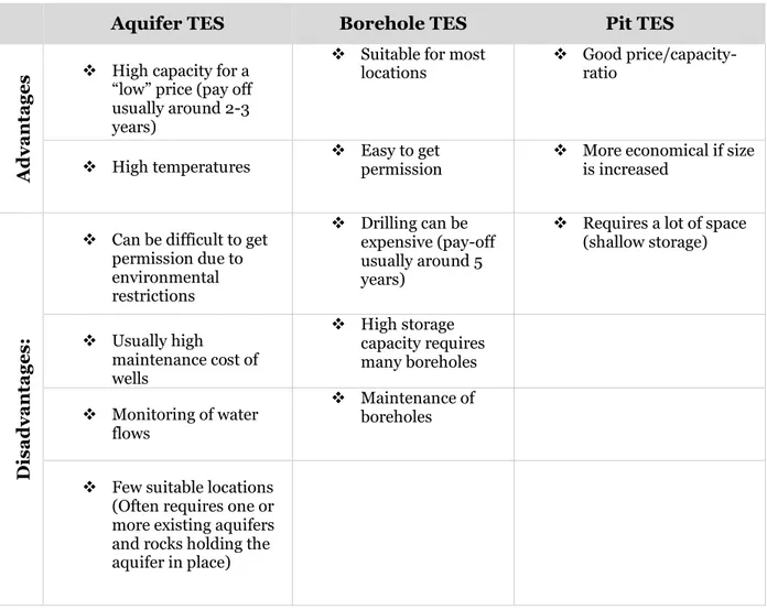
Table 2 highlights the advantages and disadvantages of different sensible energy storage types for seasonal storage (Michael Harris 2011).
Table 2: Sensible heat storage advantages and disadvantages
Aquifer TES Borehole TES Pit TES
A d va nt a g
es ❖ High capacity for a “low” price (pay off usually around 2-3 years)
❖ Suitable for most
locations ❖ Good price/capacity-ratio
❖ High temperatures ❖ Easy to get permission ❖ More economical if size is increased
Di sa d va nt a g es :
❖ Can be difficult to get permission due to environmental restrictions ❖ Drilling can be expensive (pay-off usually around 5 years)
❖ Requires a lot of space (shallow storage) ❖ Usually high maintenance cost of wells ❖ High storage capacity requires many boreholes ❖ Monitoring of water flows ❖ Maintenance of boreholes
❖ Few suitable locations (Often requires one or more existing aquifers and rocks holding the aquifer in place)
3.3 Latent heat Storage (Phase-Change Materials)
Latent heat storages (LHS) apply the phase change materials (PCMs), remove and store energy in phase transition of the PCMs. PCMs absorb heat during temperature rising. The heat absorption is like sensible material until the PCM reaches the temperature of phase transition. After phase transition temperature, PCM’s chemical bonds break and it starts to absorbs energy at constant temperature(K. S. Reddy, Mudgal, and Mallick 2018). A certain amount of heat is needed for phase transition of a substance so called latent heat of fusion and a certain amount of heat needed to be removed from a substance to come back to the former phase(Dincer and Rosen 2010). Exploiting this phase change enthalpy of PCMs, utilize the energy storage in the certain range of temperatures, depends on the characteristic of the PCMs. The typical PCMs that applied in LHS are liquid, liquid-gas and solid-solid(Scapino et al. 2017).
The storage capacity of LHS can be expressed by Equation 2. In Equation 2, 𝑇𝑚 is the melting point of the PCM. Specific heat of PCM is expressed by 𝐶𝑃𝑙 & 𝐶𝑃𝑠 in liquid and solid phases.
Enthalpy of phase change is expressed as ∆𝐻𝑚. In the case of when the specific heat is not as a function of temperature, the equation can be expressed by Equation 3(Zhang et al. 2016).
Equation 2 Heat of PCM's phase transition
𝑄 = 𝑚 ∫ 𝐶𝑃𝑠 𝑇𝑚 𝑇𝐿 𝑑𝑇 + 𝑚∆𝐻𝑚+ 𝑚 ∫ 𝐶𝑃𝑙 𝑇𝐻 𝑇𝑚 𝑑𝑇
Equation 3 Heat of PCM's phase transition when Cp is independent to temperature
𝑄 = 𝑚[𝐶𝑃𝑠(𝑇𝑚− 𝑇𝑙) + ∆𝐻𝑚+ 𝐶𝑃𝑙(𝑇𝐻− 𝑇𝑚)]
The most common LHS is known as melting-solidification cycle, at the specific constant temperature with different temperature ranges and for the specific thermal applications. The absorbed or released energy during phase transition as melting-solidification is known as the latent heat of fusion(melting). In Figure 1, the latent heat of vaporization is significantly larger than the latent heat of fusion(melting). But most of the applications of PCMs are on solid-liquid LHS system. The main reason for this, is the high density change that takes place during liquid-gas phase transition; Therefore, it requires a significant quantity of equipment that makes the application unfeasible(Fleischer 2015a).
Figure 1: Standard heating curve(Fleischer 2015a)
As described, the solid-liquid LHS is the most common type of LHS. For solid-liquid applications, PCMs are classified into the main three categories. Organic compounds, inorganic compounds and eutectics mixtures. All of these three PCMs categories are classified into the subgroups in Table 3(Lizana et al. 2017).
Table 3 Classification of solid-liquid PCMs
phase change material
Organic compound Inorganic compound Eutectics Paraffin wax Salt hydrates Organic-organic
Fatty acids Metallic Inorganic-organic
Alcohols Inorganic-inorganic
Esters
(Farid et al. 2004) reviews different kinds of phase-change materials (PCMs). The study investigates Paraffin Waxes and hydrated salt storage. The focus is on storing energy from solar energy, but it is stated that the storages can be used for other applications. It is
concluded that most organic PCMs are non-corrosive, chemically stable and exhibit little or no sub-cooling. They are also compatible with most building materials, have high latent heat per unit of weight and low vapor pressure. On the negative side, they have high volume change on phase-changes and flammability, and low thermal conductivity. (Lizana et al. 2017) in comparison with paraffin it is stated that fatty acids, esters and alcohol have higher flammability, toxicity and low thermal conductivity which limited the application of them in the building.
Inorganic compounds have higher latent heat per unit of volume, high thermal conductivity, and are non-flammable. They are also low in cost in comparison with the organic substances (Farid et al. 2004). Salt hydrates are a combination of inorganic salt (oxides, carbonates, sulphates, nitrates and halides) and water molecules. Salt and salt hydrates have a wide range of melting points that enable operating range of 10 °C to 900 °C (Fleischer 2015b). Inorganic PCMs are corrosive to most materials. Their face sub-cooling and decomposition properties can affect their phase-change capacities. Because of this, inorganic compounds require thickening agents to minimize sub-cooling and phase segregation(Farid et al. 2004). Metallic PCMs in LHS applications are not widely applied because of high weight density. But based on the high thermal conductivity, high latent heat of fusion, low specific heat and less vapor pressure, they are potential candidate in TES(K.S. Reddy, Mudgal, and Mallick 2018). Eutectic PCMs are combination of two or more PCM components, mostly inorganic and/or organic, that do not shape a new chemical compound(Lizana et al. 2017). The certain ratio of these compounds results in crystallization inhabitant that leads to lower melting temperature than its components. Thermal properties of few eutectic PCMs are known and there are further investigation in this area(K.S. Reddy, Mudgal, and Mallick 2018).
(Fleischer 2015c) reviewed the applications of PCMs in LHS. Almost 50 years ago, there was an interest in PCMs for thermal management systems. In Table 4, the most popular
applications of PCM are listed.
Table 4: most common PCM applications
PCM applications Electronic
thermal management
Building solar energy
plants domestic solar application
packed
bed design Textile design In 1970 NASA implemented PCMs as what they called “thermal capacitor” in moon vessels and Skylab. 1977 NASA published a tech brief handbook for design and control strategy of PCMs. At the same decade, there was a development in conception of embedding PCMs in building material to enhance the efficiency of energy consumption by reducing the heating and cooling load. There was also building application of TES with PCMs in solar systems for domestic hot water. TES with PCMs was interesting also for large solar plants. It was also in that decade that the studies were started on comprehensive thermophysical and numerical study of PCMs. In 1980 by significant growth in computer science and technology, PCMs material were studied and integrated to the high-performance process military, consumer electronics. Finally, the most recent application of PCMs are on textile design for energy absorbing clothing.
In depth review of PCMs is not in the scope of this thesis but worthy to have a general review as one of the TES alternatives.
3.4 Thermochemical heat storages (THS)
Thermochemical heat storage (THS) absorbs heat during a reversible chemical reaction and release it in the reverse reaction(Zhang et al. 2016). Thermochemical heat storages have an excellent energy density in comparison with other methods of storing heats(Aydin, Casey, and Riffat 2015). A chemical reaction that mostly is under constant pressure can equates in this form:
𝑅𝑒𝑎𝑐𝑡𝑎𝑛𝑡𝑠 → 𝑃𝑟𝑜𝑑𝑢𝑐𝑡𝑠
Standard Enthalpy of reaction ∆𝐻°
𝑟𝑥𝑛 is the difference between summation of enthalpies of
products and summation of enthalpies of reactant. ∆𝐻°
𝑟𝑥𝑛 = ∑ 𝐻°(𝑝𝑟𝑜𝑑𝑢𝑐𝑡𝑠) − ∑ 𝐻°(𝑟𝑒𝑎𝑐𝑡𝑎𝑛𝑡𝑠)
Sign of enthalpy of reaction defines the nature of reaction whether it is endothermic or exothermic(Chang and Goldsby 2012). THS applies the reversibility of chemical reaction to absorb, store and release energy in the form of heat. In a reversible chemical reaction, heat can be released/stored when the bounds between the reactants breaks. Thermochemical heat storage can be expressed with different terminology “chemical”, “thermochemical sorption”, “sorption” and “compact storage”(Fopah Lele n.d.).
One of the most important information is the temperature which reaction proceeds in a favorable manner. For thermochemical energy storage we can express this temperature as operating temperature or condition. Due to second law of thermodynamic: the entropy of the universe increases in a spontaneous process and remain unchanged in an equilibrium
process.
(Chang and Goldsby 2012) states that the standard entropy of reaction ∆𝑠𝑟𝑥𝑛 is important to study the spontaneous condition of reaction and it can be expressed as follow:
∆𝑆°
𝑟𝑥𝑛 = ∑ 𝑆°(𝑝𝑟𝑜𝑑𝑢𝑐𝑡𝑠) − ∑ 𝑆°(𝑟𝑒𝑎𝑐𝑡𝑎𝑛𝑡𝑠)
To clarify and making the spontaneity of reaction clear, the thermodynamic term Gibbs free energy is important for calculation of the suitable operating temperature of chemical reaction in constant pressure and temperature. The free energy 𝐺 is expressed as:
Equation 4 Gibbs free energy
𝐺 = 𝐻 − 𝑇𝑆
Both terms at the right side of the Equation 4, is in the form of energy unit enthalpy and entropy of the system. T is the temperature of the system. G has the unit of energy like S and H. G is a state function. The change in free energy of the system can be expressed by:
∆𝐺 = ∆𝐻 − 𝑇∆𝑆
T is the constant-temperature of the system and Free energy is the available energy to do work. Due to entropy changes in the system and the enthalpy changes of the system at the specific temperature that makes ∆𝐺 negative enough it guaranties that the reaction is
spontaneous. With those range of temperature (T) that makes ∆𝐺 positive, the system is nonspontaneous in the opposite direction. When ∆𝐺 = 0 system is at equilibrium(Chang and Goldsby 2012).
By finding the equilibrium condition (∆𝐺(𝑇∗) = 0), the transition temperature, 𝑇∗ , at the
given standard pressure can be determined with Equation 5. During charging 𝑇 > 𝑇∗ which
decomposition dominates. When 𝑇 < 𝑇∗ synthesis dominates and the discharging takes place
in the system(Alva, Lin, and Fang 2018).
Equation 5 Transition temperature of chemical reaction
𝑇∗=∆𝐻(𝑇∗)
∆𝑆(𝑇∗)
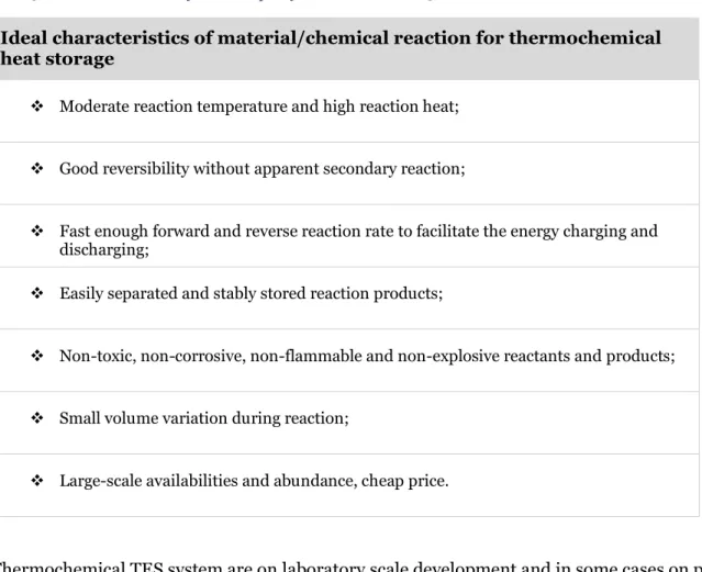
The ideal thermochemical heat storage material selection generally characterized with these items that summarized in the Table 5(Yan et al. 2015).
Table 5 Ideal characteristics of TCM adapted from (Yan et al. 2015)
Ideal characteristics of material/chemical reaction for thermochemical heat storage
❖ Moderate reaction temperature and high reaction heat;
❖ Good reversibility without apparent secondary reaction;
❖ Fast enough forward and reverse reaction rate to facilitate the energy charging and discharging;
❖ Easily separated and stably stored reaction products;
❖ Non-toxic, non-corrosive, non-flammable and non-explosive reactants and products;
❖ Small volume variation during reaction;
❖ Large-scale availabilities and abundance, cheap price.
Thermochemical TES system are on laboratory scale development and in some cases on pilot projects. Development of thermochemical heat storage is a multi-disciplinary work that requires development from different technical engineering before it commercially becomes viable in operation(Pardo et al. 2014). (Garg, Mullick, and Bhargava 1985) &(Pardo et al. 2014) identified the technical disciplines that is essential in development of thermochemical TES system in Table 6.
Table 6: Technical development of THS adapted from(Pardo et al. 2014; Garg, Mullick, and Bhargava 1985)
inter-disciplinary of thermochemical heat storage material/chemical reaction chemistry process engineering material heat transfer system analysis reaction selection operating process
plant corrosion reactor/heat exchanger design technical and economic feasibility studies
reversibility process sizing impurities factor catalytic reactor
design process safety reaction rates process
optimization inexpensive materials of construction
improving the heat
transfer cost benefit studies
operating condition thermodynamic optimization catalyst lifetime
kinetic
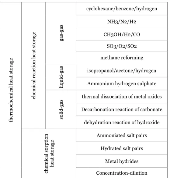
Chemical reaction can be classified into two main groups. Chemical reaction heat storage without sorption and chemical sorption heat storage. The most typical and promising candidate reaction for both chemical reaction and sorption chemical reaction based on the phase of reactor and reactance summarized in Table 7, by (Yan et al. 2015).
Table 7 Thermochemical reaction classification with some promising candidate(Yan et al. 2015)
the rm oche m ica l he at sto ra ge che m ica l r ea cti on he at sto ra ge ga s-ga s cyclohexane/benzene/hydrogen NH3/N2/H2 CH3OH/H2/CO SO3/O2/SO2 methane reforming liqu id -g as isopropanol/acetone/hydrogen
Ammonium hydrogen sulphate
so
lid
-ga
s thermal dissociation of metal oxides
Decarbonation reaction of carbonate dehydration reaction of hydroxide
che m ica l s or ptio n he at sto ra ge
Ammoniated salt pairs Hydrated salt pairs
Metal hydrides Concentration-dilution
3.4.1 Ammonia based chemical reaction
The chemical reaction is 2𝑁𝐻3(𝑔) ↔ 𝑁2(𝑔) + 3𝐻2(𝑔) with the reaction enthalpy of 66.8 𝑚𝑜𝑙𝑘𝑗
ammonia at 20 MPa and 300 K. Technical feasibility of ammonia-based TES system for concentrating solar power has been proven among different studies. A concentrating solar plant with 400 larges dishes, with area of 400 𝑚2 arranged in array can supply a 10 MW base
load plant with a synthesis reactor by rate of 1500 t/day. The heat of the synthesis reaction can utilize a power cycle to produce the superheated steam at 793 K and pressure of 10 MPa(Yan et al. 2015). (Chen et al. 2018) presents the advantages of ammonia based THS as follows, relative to other technologies:
❖ Single step reversible dissociation-synthesis reaction without any side reactions with essential control of the reaction path.
❖ All elements, Ammonia, nitrogen and hydrogen remain stable at the operating temperatures. ❖ Both reactants and products are abundant.
❖ Automatic phase separation in ambient temperature because of the large density difference between ammonia and hydrogen/nitrogen gas mixture, which leads to that, they can be stored in the same tank.
❖ The enormous industrial experience with ammonia synthesis is available(Chen et al. 2018).
3.4.2 Sulphur trioxide (𝑺𝑶𝟑) dissociation
Another promising candidate for gas-gas chemical reaction is the chemical reaction of Sulphur trioxide (𝑆𝑂3) stand on the reversible dissociation of 𝑆𝑂3.
2𝑆𝑂3(𝑔) ↔ 2𝑆𝑂2(𝑔) + 𝑂2(𝑔)
Decomposition proceeds in temperature range of 1073-1273 K without any unwanted side reaction. Reactivity enhancement can be done with presence of a proper catalyzer. In this form of THS the gases 𝑆𝑂2, 𝑂2 from dissociation reaction are deliverable with pipes for
heating purposes. In one study with integration of this chemical reaction THS with a solar plant steam cycle, the heat storage system efficiency is about 58% with overall conversion efficiency from thermal to electric energy of 26%. The related solar power plant steam cycle’s efficiency is about 40%(Yan et al. 2015).
3.4.3 Methanol decomposition
The decomposition of methanol is a potential candidate for low temperature application since the decomposition takes place in low temperature.
The good properties of methanol decomposition are that it is cheap, clean and can be stored conveniently. There is a proposal for two step liquid-phase including the intermediate products methyl as follows:
𝐶𝐻3𝑂𝐻 + 𝐶𝑂→𝐻𝐶𝑂𝑂𝐶𝐻3 ; 𝐻𝐶𝑂𝑂𝐶𝐻3 + 2𝐻2 → 2𝐶𝐻3𝑂𝐻
The two-step decomposition, by conversion ratio of 90% can reach the transportation efficiency of 75% (Yan et al. 2015).
3.4.4 Methane reforming
Methane reforming chemical reaction as THS is another promising candidate in application of solar heat and industrial waste. The temperature of endothermic reaction is high. By reversible exothermic reaction, as a positive point, there is a possibility of long distance transportation of the gas as the product of reforming reaction. As a result, methane
reforming reaction is a potential and effective candidate for on operation energy system with means of utilization and optimization. Methane reformation with water or carbon dioxide widely applied in industrial production with 𝐶𝑂2 or steam reforming(Anikeev et al. 1998). But solar reforming of methane got a great attention recently.
𝐶𝐻4(𝑔) + 𝐻2O →𝐶𝑂(𝑔) + 3𝐻2(𝑔) 𝐶𝐻4(𝑔) + 𝐶𝑂2(g) → 2𝐶𝑂(𝑔) + 2𝐻2(𝑔)
Theoretically, by supplying the heat of endothermic reaction of methane reforming to produce syngas via solar power plant, the calorific value of feedstock methane can be upgraded by 22-28 %. The CH4/CO2 reforming is superior in comparison to CH4/H2O reformation. The side reaction, water-gas shift and insufficient exothermic heat rate are drawbacks for CH4/H2O. Solar reforming of CH4/CO2 has had experimental feedback more than 20 years. The solar CH4/CO2 provide the energy or in other words, store the energy into a high-grade energy as well as reducing the CO2 emission(Yan et al. 2015).
(Brown et al. 2014) clarify the impact of syngas as the product of methane reforming THS with an example. The General Electric syngas turbine, 7FA, has a capacity of 232 MW. In comparison to the same turbine but, natural-gas fired, 7FA, has 3% higher LHV efficiency. For combined cycle it has even more advantages. The syngas-fired combined cycle plant has 10 % higher efficiency than natural gas fired combined cycle power plant correspondingly 67.9 % and 57.5 %.
3.4.5 Ammonia hydrogen sulfate chemical reaction:
(Wentworth and Chen 1976) investigated the decomposition of ammonium hydrogen sulphate. The author constructed 10 criteria for applicability of a reaction with means of thermochemical heat storage. Ammonium hydrogen sulphate satisfied all these criteria and it is a promising reaction.
The endothermic reaction temperature and exothermic released temperature depend on the condition of the reaction. The thermal energy storage density varies between 3.098 and 4.102
𝐺𝐽
𝑚3 by storing 𝐻2𝑂, 𝑁𝐻3, 𝑆𝑂3 as liquids at ambient pressure. Two-step reaction proposed for an effective separation of 𝐻2𝑂, 𝑁𝐻3, 𝑆𝑂3 . The endothermic reaction, by employing one metal
sulphate( 𝑀2𝑆𝑂2) to form intermediate pyrosulphate ( 𝑀2𝑆2𝑂7). The decomposition of (
𝑀2𝑆2𝑂7) leads to an effective decomposition of ( 𝑀2𝑆2𝑂7) in a way that gas product of
decomposition (𝐻2𝑂, 𝑁𝐻3, 𝑆𝑂3) can be condensed for long term transportation and storage(Yan et al. 2015).
(Wentworth and Chen 1976) investigated twenty-five metal oxides, among them, 𝑍𝑛𝑂 was the best intermediate reagent for this reaction that gives the best separation in decomposition. 𝐻2𝑂(𝑔) at temperature of 436 K, 𝑁𝐻3(𝑔) at temperature of 638-691 K and the mixture of 𝑆𝑂2 𝑎𝑛𝑑 𝑆𝑂3 at temperature of 1173 k. The endothermic reaction, by employing the 𝑍𝑛𝑆𝑂4
was also very fast and progressive at temperature of 1123 K.
3.4.6 Redox system:
Storing and release or retrieval of heat takes place during the reduction and re-oxidation of solid metal oxides in REDOX (reduction and re-oxidation) system. During charging, the oxide undertakes a reduction. During discharge, by employing cool air, heat releases during the re-oxidation. In the REDOX system both heat transfer fluid and reactant can be
air(Project Staff 2011). In one study due to the study of 74 metal oxide reaction with chemical reaction and equilibrium software (HSC), these pairs nominated as the potential candidate for THS, in operating range temperature of solar thermal power plant(STPP)(Agrafiotis, Roeb, and Sattler 2016).
2𝐵𝑎𝑂2+ ∆𝐻 ↔ 2𝐵𝑎𝑂 + 𝑂2; 𝑇𝑒𝑞𝑢𝑖𝑙𝑖𝑏𝑟𝑖𝑢𝑚= 690°𝑐; ∆𝐻 = 474𝑘𝐽 𝑘𝑔 2𝐶𝑜3𝑂4+ ∆𝐻 ↔ 6𝐶𝑜𝑂 + 𝑂2; 𝑇𝑒𝑞𝑢𝑖𝑙𝑖𝑏𝑟𝑖𝑢𝑚 = 870°𝑐; ∆𝐻 = 844𝑘𝐽 𝑘𝑔 6𝑀𝑛2𝑂3+ ∆𝐻 ↔ 4𝑀𝑛3𝑂4+ 𝑂2; 𝑇𝑒𝑞𝑢𝑖𝑙𝑖𝑏𝑟𝑖𝑢𝑚= 1000°𝑐; ∆𝐻 = 204𝑘𝑔𝑘𝐽 4𝐶𝑢𝑂 + ∆𝐻 ↔ 2𝐶𝑢2𝑂 + 𝑂2; 𝑇𝑒𝑞𝑢𝑖𝑙𝑖𝑏𝑟𝑖𝑢𝑚= 1030°𝑐; ∆𝐻 = 811𝑘𝐽 𝑘𝑔
Barium oxides showed a good potential but, some difficulties in reaction conversion in kinetic studies considers as the draw back(Pardo et al. 2014). Direct thermal dissociation of metal oxides is quite energy consuming and difficult in practice. In some studies the binary
iron/cobalt oxide shows a good structural ability that leads to long duration reversibility with 10% iron at the same time maintaining the enthalpy sufficient for THS (Yan et al. 2015). (Agrafiotis, Roeb, and Sattler 2016) reviewed different redox pairs and characterized each pair for the application of air operated STPP. The study concluded that there are a series of challenges in the real-world application of barium oxide as THS. The study predicts the trends of REDOX system development in combination of two single metal oxides for large scale application.
3.4.7 Reversible chemical reaction of Metal hydroxide
The reaction of metal oxides with water(steam) is a possible choice for heat storage
application. The most typical metals that has this potential are in groups of the alkaline and alkaline earth metal. Mg(OH)2 , Ca(OH)2, Sr(OH)2 or Ba(OH)2 and LiOH are heat storage materials but most of the investigations and experimental laboratory are for magnesium hydroxide and calcium hydroxide(Felderhoff, Urbanczyk, and Peil 2013).
Calcium oxide chemical reaction with water is one of the high energy density TCM. The operating temperature depends on the steam partial pressure, can varies between 623 K and 1173 K, respectively, for 0 to 2 bar steam partial pressure. With high experimental material energy density of 200𝑘𝑊ℎ𝑚3 , high number of reversible cycles, no by product, product
separation, the high availability and low price, non-toxic product and over 10 years of experimental feedback on reaction and its technology, calcium oxide has a high potential of utilization in large scale THS. Some challenges in applying this reaction as THS is
agglomeration and sintering, change of volume to 95% and low conductivity(Pardo et al. 2014).
𝐶𝑎(𝑂𝐻)2(𝑠) + ∆𝐻 ↔ 𝐶𝑎𝑂(𝑠) + 𝐻2𝑂(𝑔); ∆𝐻 = 104 𝑘𝐽
𝑚𝑜𝑙
As mentioned with more than 10 years of experience feedback in applying salt in THS, there are further improvement in the technology of salt. SaltX Company (former Climatewell AB) in Sweden developed a method of salt treatment in year 2011 to enhance the capability of Calcium oxide and or salt hydration. One of the main drawback of THS materials is corrosive reaction in contact with atmospheric tank during absorption. SaltX developed a method to manufacture a particle consists of a salt (Cao) as inner part and hydrophobic nanoparticles as the outer coating of particle. The advantages of these particles (Nano coated calcium oxide) is eliminating the effect of corrosion almost completely by enclosing the salt within the
hydrophobic nanoparticles. This leads to long term stability of the absorption machines and open new horizons for the application of salt material in form of chemical reaction. The form of NCS stops the salt migration in liquids or gas phases. 100 times greater surface contact claimed to be achieved with NCS particles in compare with the common salt absorption. NCS particles reduce the system costs by eliminating the needs of expensive circulating pump and corrosion inhibitor injection package as the PH buffer to counteract with corrosion(Bolin and Glebov 2016).
Magnesium hydroxide with operation temperature between 450-550K for charge and discharge(Felderhoff, Urbanczyk, and Peil 2013). Sufficient reaction rate both forward and backward approved in some studies for this reaction to apply it for TES(Pardo et al. 2014). 𝑀𝑔(𝑂𝐻)2(𝑠) + ∆𝐻 ↔ 𝑀𝑔𝑂(𝑠) + 𝐻2𝑂(𝑔); ∆𝐻 = 81𝑚𝑜𝑙𝑘𝐽
3.5 Energy storage for CHP
(Aravindh Murali 2017) reviews both latent heat storage and PCM that can be used with CHP-plants. It is stated that implementation of a TES into the combined CHP plants has great potential for increasing the energy efficiency in industries. By introducing a SHS(tank) the energy efficiency and flexibility of the CHP is increased, while CO2 emissions and energy consumption is decreased. The CHP can also operate more continuously and increase the operating hours of the plant. When properly optimizing and controlling the operation of the TES, the Combination of CHP and TES can adapt to areas with high renewable penetration. New technologies for heat storage will have the ability to further increase the energy
efficiency and reduce costs.
Researchers at University of Liége in Belgium (Sartor and Dewallef 2017) investigated the benefits of integrating SHS (tank) into DHN. The model is applied to the DHN of University of Liége. The model is built to estimate the economic, environmental, and energetic
performance of the CHP plant when connected to DHN. Both seasonal and short-term use of the SHS is evaluated. They conclude that an hourly optimal volume of the storage can be found, but SHS is not feasible from an economic standpoint due to long pay-back time and lack of subsidies from the Belgian government. For seasonal storage, it is not possible to find an optimal volume and large investment costs combined with few operating hours means that it is not economical.