SKI Report 99:28
Design Basis for the Copper/Steel Canister
Stage Five. Final Report
ISSN 1104-1374 ISRN SKI-R--99/28--SE
William Henry Bowyer
SKI Report 99:28
Design Basis for the Copper/Steel Canister
Stage Five. Final Report
William Henry Bowyer
Meadow End Farm, Tilford, Farnham, Surrey. GU10 2DB, England
May 1999
This report concerns a study which has been conducted for the Swedish Nuclear Power Inspectorate (SKI). The conclusions and viewpoints presented in the report are those of the author and do not necessarily coincide with those of the SKI.
Summary
The development of the copper/iron canister which has been proposed by SKB for the containment of high level nuclear waste in the Swedish Nuclear Waste Disposal Program, has been studied by the present author from the points of view of choice of materials, manufacturing technology and quality assurance. Earlier reports1, 2,3 describe observations made in the period to April 1998.
This report describes the observations on progress that has been made between May-1-1998 and April-30-1999 and the result of further literature studies.
Cast steel has been rejected in favour of cast iron as a candidate material for the load bearing liner. The nodular iron that was selected has been the subject of casting trials at several foundries. Early trials, using uphill feeding, met with limited success owing to difficulties feeding during solidification. Lessons from this trial led to a modification to the casting design to include extra cores that have the effect of reducing the need for feeding in the heaviest sections. Results using the new design and direct (downhill) casting are very promising. Castings appear to be sound and mechanical test results cast-on bars are within specification. Tensile test results from specimens cut from the casting have reduced ductility compared with the cast-on bars and this may be evidence of microstructural variations within the casting.
The material specified for the overpack is OF (Oxygen Free) copper with 50 ppm of phosphorus added. Concentration limits have now been placed on impurity elements which are below those allowed in the OF specification. All current trials are using material from Outokompu produced from cathode on their OF(E) line, which delivers total impurity levels of less than 30 ppm excluding silver and phosphorus. The
phosphorus addition is made using a master alloy added to the launder and this does not give good control of phosphorus level either within or between castings. Phosphorus is added to improve creep rates and creep strain to failure. The level is limited to 50ppm in order to avoid difficulties, which it might cause, in electron beam welding. The
improvement in creep strength conferred by the phosphorus is valuable, but the
evidence that is available suggests that the influence of phosphorus is very complicated. A view is expressed that further work is required to understand the coupling between the effects on creep properties of phosphorus, processing and grain size. The writer is concerned that the problem of low creep ductility may not have been overcome. It has been recognised that the roll forming method is not suitable for serial production and this approach has been abandoned.
Two candidate processes are under investigation for tubular production. These are extrusion and a pierce and draw process, which is similar to backward extrusion. Both these methods are more suitable for serial production and there is a reasonable prospect that either may be developed to provide a satisfactory metallurgical structure. A further option under investigation is reduction of the thickness of the overpack from 50 mm to 30 mm.
Very good results have been achieved by using an extrusion temperature of 675 °C and the problem of controlling grain size in the tubular appears to have been overcome. The pierce and draw process has the advantage that it produces a tubular with an integral bottom. The first trial with this process used a processing temperature of 800 °C. The resulting grain size was very coarse and the draw did not continue to
completion. Further trials are planned.
A new electron beam welder has been developed to overcome the problems, which have beset the earlier trials. It has been supplied to the SKB pilot plant where commissioning is in progress. An alternative welding process, friction stir welding, is being examined as a candidate for attaching lids. This is potentially a more favourable process than electron beam welding but it is in an early stage of development.
Ultrasonic and radiographic test equipments have been developed for examination of lid welds. They have been supplied to the SKB canister laboratory where they will undergo commissioning and calibration trials.
Contents
SUMMARY ...3
CONTENTS...5
1. INTRODUCTION ...7
2. PROGRESS ON CANISTER DEVELOPMENT...8
2.1. Materials Selection...8
2.1.1. The Load Bearing Liner ... 8
2.1.2. The Copper Overpack ... 8
2.2. Technology Developments ... 11
2.2.1. The Load Bearing Liner ... 11
2.2.2. The Copper Overpack ... 13
2.2.2.1. Ingot Casting... 13
2.2.2.2. Fabrication ... 15
2.2.2.3. Extrusion... 15
2.2.2.4. Pierce and Draw ... 16
2.2.2.5. Forged lids ... 18
2.2.2.6. Welding ... 20
3. ANNEALING OF O.F. COPPER ...21
4. NON DESTRUCTIVE TESTING ...21
5. CONCLUSIONS ...21
6. REFERENCES ...22
1. Introduction
This is the final report on stage five of a consulting assignment aimed to assist SKI in understanding and reviewing the work of SKB on the development of the composite canister for long term storage of high level nuclear waste. The writer’s views on the status of the programme at April 30 1998 are summarised in earlier reports1, 2,3. The activities in the 1998/99 assignment are as follows,
(1) Continuing liaison with SKB at meetings arranged in Stockholm and at the premises of their contractors, members of SKI would be present at these meetings. The purpose of these liaisons would be, to understand and report on the technology developments. These would include,
(1) Monitoring the production of cast liners, commenting on casting technology, quality and quality assurance procedures.
(2) Consideration and comment on the procedures for attaching lids. (3) Monitoring and commenting on, progress towards casting large
ingots suitable for extrusion or piercing and drawing procedures, extrusion research and development, pierce and draw research and development, welding research and development and non destructive evaluation proposals/progress.
(4) Observation of the quality of the starting materials and the effects of processing on the microstructures and their properties.
(2) Reading and commenting on the component of the 1998 FUD report from SKB4 related to canister technology.
(3) Monitoring and commenting on SKI commissioned studies on annealing of OF copper at the University of Linkoping.
(4) Attending four discussion meetings in Sweden to report on progress and to support SKI in interpretation of further work carried out on behalf of SKB or SKI.
Two important reports from SKB5, 6 emerged in August and September 1998, they are form the basis of the canister section of SKI’s “Detailed programme for research and development 1999-2004”4 (FUD 98) which emerged in September 1998. Detailed comments on these three reports part which form part (2) of this current programme are presented elsewhere7. Some of the comments are repeated in this report for the sake of completeness.
2. Progress on canister development
2.1. Materials Selection
2.1.1. The Load Bearing Liner
The decision to change from a fabricated steel liners to cast liners has been previously discussed3. On liners produced to date the bond between the seamless tubes used as cores and the cast iron has been poor. SKB do not see this as a problem and nor do I provided that cooling contractions do not lead to unacceptable buckling of the walls of the seamless tubes. The lack of bonding is presumably a consequence of the discrepancy in melting points of the iron and the steel, which could be in the region of 300 °C. Andersson6 has disclosed that test bars have been cast with each ductile iron liner and that one liner had been sectioned for mechanical tests and microscopical examination. Results from tests6 on these specimens indicate that all the casts on test bars were within specification for the iron on yield strength, UTS and ductility. Test bars cut from
sections of the casting tended to have much lower ductility however. The changes in ductility reported (from 20% on test bars to less than 10% on specimens cut from a casting) are an indication of some variation in structure between the cast on test bars and the material from the casting. An increase in yield strength, which is observed between specimens cut from the bottom of the casting and specimens cut from the middle, suggests that there is also some variation of structure within the castings. Whilst this is not seen as problem at this level, the cause should be investigated.
In due time it will be necessary to carry out sufficient tests on material cut from cast inserts to give a confident determination of the range of material properties and structures which occur in real castings. The variations in microstructure within single castings and between castings and the location, type and frequency of occurrence of casting defects should be determined as part of the same exercise.
Werme5 has stated that calculations for a cast canister with internal support, according to the current concept indicate that, the critical stress for failure, based on ideal
properties in the cast iron, are 81 MPa for the BWR version and 114 MPa for the PWR version. These appear to offer good safety margins over the proposed design basis case (44 MPa when 3000-meter thick ice is accounted, otherwise 14 MPa).
2.1.2. The Copper Overpack
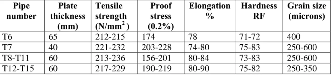
An earlier report3 gave detailed descriptions of the materials used for the production of tubulars by extrusion and by fabrication from plate. No further changes are reported. A total of ten tubulars has been made by roll forming and seam welding. Nine are in 60-mm thick plate and one is in 40-60-mm thick plate. It has been said that if 40-60-mm thick plate were used then the thickness of the liner would be increased to provide the extra shielding which would be required.
During the year mechanical property and grain size information for plate used in the manufacture of tubulars has become available8 and is summarised in table 1 below.
Table 1 Properties of plates used for fabricated tubulars
Pipe
number thicknessPlate (mm) Tensile strength (N/mm2 ) Proof stress (0.2%) Elongation
% HardnessRF Grain size(microns)
T6 65 212-215 174 78 71-72 400 T7 40 221-232 203-228 74-80 75-83 250-600 T8-T11 60 213-236 156-201 80-84 73-83 250-600 T12-T15 60 217-229 190-219 80-90 75-82 250-350 The mechanical property information is unremarkable, it does show how very soft the material is but this is to be expected. The grain size is very coarse for all materials and the reported figures are somewhat finer than the values measured by the writer on similar materials. Whilst it is common for reasonably fine grained material to estimate grain sizes using the ASTM comparator charts and to convert to grain diameters using a conversion table, this process can lead to serious inaccuracies for materials like the ones under consideration which have very mixed coarse grain sizes. These inaccuracies are significant when the estimates are used to calculate the concentration of segregates to grain boundaries.
The results of this work are now academic as SKB have decided that the roll forming approach is not a serial production process and that this approach should be abandoned. The ingots for extrusion or pierce and draw processing are specified as OF Copper with 50 ppm Phosphorus added and also with other elements limited to the values given in ppm, below.
Ag As Fe S Sb Se Te Pb Bi
25 5 10 <8 4 3 2 5 1
Cd Mn Hg Ni Sn Zn H P O
1 0.5 1 10 2 1 <6 40-60 5
So far suitable ingots have only been made by Outokompu at their Pori works and the specification has been designated as OFEP-OK. This grade is made from cathode which is more pure than the OF specification demands. It is produced in the casting line for Outokompu`s grade OF (E) which typically has impurity levels (excluding silver) of less than 30 ppm9.
The reasons for adding phosphorus that have been given by SKB are to increase
recrystallization temperature and improve creep strength and creep ductility. The reason given for limiting it to 50 ppm is to avoid adverse effects of phosphorus during electron beam welding. The manufacturing trials to date have resulted in analysis values lying between 40 ppm and 85 ppm9. There is no published information at present on any likely effects of this variation in phosphorus content. It is a function of the process and it may be very difficult to control. Detailed information on the critical level of
phosphorus for electron beam welding is not currently available. It is not clear whether or not problems experienced in welding to date are related to this variability. The casting method (see section 2.2.2) for the ingots, does not allow close control over phosphorus levels and this accounts for the high variability seen to date. It may be
necessary to determine the level of phosphorus that can be tolerated by the electron beam welding process if this is eventually adopted for production use.
The SKB work on the effects of phosphorus on creep properties has been carefully re-examined 10,11,12. The most recently published work, Henderson and Werme 10,
compares the results of creep tests on 30 specimens, which include 10 different types. The number of tests for each specimen type is therefore rather small.
The results suggest that at constant grain size, for extruded material tested at 215 °C and 100 MPa, creep rates are reduced by a factor of 100 by the addition of 50-ppm
Phosphorus. Also Phosphorus bearing material, processed by hot rolling and having a grain size of 115 µm (compared with 45 µm for the extruded material) tested under the same conditions has a creep rate which was 10 times faster than the extruded
phosphorus bearing material. If these observations are taken at face value, it seems that either hot rolling rather than extrusion, or a change in grain size from 45 µm to 115 µm or a combination of both causes a ten-fold reduction in creep rate. This effect is
sufficiently large to justify further examination.
All of the specimens used in the tests referred to above had 6 ppm Sulphur and, whilst the phosphorus free material had lower fracture strains than the phosphorus bearing material, non had the very low fracture strains (circa 1-3 %) which have been the cause of concern1, 2,3. It is now accepted that the very low creep ductility that has been
observed in coarse-grained material arises as a result of segregation of sulphur to grain boundaries. It is also accepted that for fine-grained material, the problem may be avoided by controlling sulphur levels to less than 6 ppm. It is not surprising therefore that the low creep ductility was not observed, the grains were fine and the sulphur level was 6 ppm.
All the remaining specimens had less than 3 ppm sulphur and are therefore not relevant to the argument concerning poor creep ductility caused by segregation of sulphur or to the practical case. There is still no evidence that additions of phosphorus improve the creep strain to fracture of coarse-grained material and there is every reason to expect that the upper limit of sulphur content should be lower for coarse grained material than it is for fine grained material.
A very limited number of tests on material taken from welds are reported in the work referred to above. Specimens of phosphorus free material were cut so that the entire gauge length was weld metal. The specimen long axes were either along the weld direction or perpendicular to the weld direction. Specimens of phosphorus bearing material were cut to include a transverse section of the weld, which would be part weld metal and part parent metal.
There are too few results to reveal any difference in creep properties that might arise as a result of the addition of phosphorus in these weld materials. In addition, the effects of different specimen types could mask any effects of phosphorus.
Two specimens of the phosphorus free welds failed at unacceptably low fracture strains. The reason for this is not clear, as they are also very low in sulphur. They were coarse grained and they could be providing evidence to support the view that very low sulphur levels may be required when this is so.
At this stage the results of creep tests are too few and too disparate to allow firm
conclusions to be drawn. There is however sufficient information to demonstrate a need for a comprehensive creep testing program designed to improve our understanding of the creep properties of the overpack material both including and remote from the welds. The yield strength of the copper is of order 50 MPa (depending on grain size and
mechanical condition). The calculations for the unsupported steel lid, reported by Verme6, indicated tensile stresses exceeding 250 MPa for a pressure in the repository of 27 MPa. Since the forces on the lid are transmitted through the overpack, it seems probable that, on the lid and near corners, the yield stress or creep stress of the copper could be exceeded at very modest repository pressures, even for the current design of insert. This is worthy of further examination since deformation of this type could seriously damage the system for lifting and retrieval which is provided for in the design of the lid, or even lead to extreme thinning of the lid by flow or failure by creep.
2.2. Technology Developments
2.2.1. The Load Bearing Liner
So far a total of eight nodular iron liners have been cast. Seven of these are to the BWR design and one to the PWR design. A further twenty-three are planned before the end of the year 2001. Of these seventeen will be to the BWR design and six to the PWR design. Six steel canisters have been cast to the BWR design but the results were not encouraging and consideration of steel castings was abandoned. In the forward program only nodular iron will be used, three different foundries will be trailed and progressive improvement in quality is expected.
All the castings made to date have been examined, either in the SKB storage area at Kockums or at the Valmet foundry in Karlstad. Some of the earliest castings appeared to have been repaired at various points on the surface opposite the heavy sections. It was disclosed that these were the bottom fed (uphill cast) castings. The repairs were made after removing feeders. Feeding had been inadequate and pipe (shrinkage) defects had been present.
Additional cylindrical cores had been added in the heavy sections of later castings and whilst this had helped it had not eliminated the problem.
A breakthrough in quality improvement had come with a change from uphill casting to direct casting (also incorporating the cylindrical cores in the corners). The need for feeders had been eliminated and there were no obvious surface defects on the castings made this way. It was later reported (CGA-verbal) that no defects have been revealed on machining the small number of castings which have been prepared for demonstration purposes or for use in trials.
To date all directly cast liners in nodular iron have been made at the Valmet foundry at Karlstad in Sweden. The foundrymen at Karlstad are very experienced in the production of large and complex castings in nodular iron. Their recommendation for this case was that direct casting should be employed.
The mould used is a resin bonded sand mould and the core is a fabricated assembly of steel tubes that are filled with sand. Feeding, is from a tundish through a series of refractory nozzles (pencil gates) into the heavier sections of the casting. The number and the diameter of the nozzles is controlled to enable filling of the mould in 90 seconds whilst avoiding turbulent flow in the mould and jetting onto the mould wall. The casting temperature is 1330 to 1350°C and cooling takes 48 hours. It is claimed that whilst the flow of metal is streamlined it causes sufficient stirring of the metal in the mould to enable the slag to float out. The possibility of slag inclusions in the casting is therefore reduced.
Cast-on test bars are made with each casting and the mechanical test results referred to in section 2.1.1 compare results from these test bars with results taken from a single casting that has been sectioned.
The key area of the casting influencing the strength properties is the outer 50 mm skin. This area can be examined by ultrasonic testing using a water jet probe and Valmet claim to detect all of the defects where the effect is greater than that of a 3 mm flat-bottomed hole. Surface defects (cracks and inclusions) may also be detected by magnetic particle testing. Indications arising from an ultrasonic examination may be checked using X radiography or gamma radiography but in view of the size and shape of the casting this could be a very complex and difficult procedure.
There is no developed test procedure for detecting defects that are deep between the webs in the casting. The disbond between the steel tube, which acts as a core, and the casting, will prevent the use of ultrasonic inspection from inside the steel tubes to detect voids or cracks in the webs.
The direct casting procedure described above has been discussed with Professor John Campbell who is head of the University of Birmingham Interdisciplinary Research Centre on Casting Technology. Campbell13has confirmed that using this practice, some splashing of hot metal would create dross during mould filling. However the turbulence and long solidification time will allow the dross to float out or settle against the wall of the mould. This benefit arises from the rapid filling of the mould using pencil gates. In his opinion this would be lost if bottom feeding were employed (it would be slower and less turbulent and the coldest metal would be on top).
The solidification time is estimated at 30 minutes plus14 depending on superheat. This together with the thick sections should allow convection currents in the molten metal to assist in feeding and removal of gas bubbles by floatation. Coupled with the long cooling time, it should also ensure that the structure is ductile right through. However the long solidification time can lead to the formation of coarse graphite particles and to segregation of graphite nodules by floatation. Such coarse graphite particles and segregation would lead to variations in strength and ductility.
Such graphite coarsening and segregation would be detected by examination of
microstructure and by tensile testing of test bars taken from the top and bottom discards. It would be controlled by the degree of superheat employed. The superheat should be the minimum required to allow floating out of dross and gas bubbles. Campbell13 has suggested that a superheat of 40 °C (corresponding to a casting temperature of 1200 °C) should be adequate but the optimum would be determined by practice.
2.2.2. The Copper Overpack
2.2.2.1. Ingot Casting
Owing to the very large size of the ingots which are required for pierce and draw or extrusion processing, (1m diameter and 2.6 m long) it is not possible to use fully continuous casting. Semi-continuous casting is used and a single ingot is cast in each run. The casting rate of 4-5 cm per minute, which is unusually slow, is limited by the rate of melting in the furnace and the rate of cooling in the mould. Since it would be very difficult to increase the rate of cooling in the mould and to produce more than one ingot in a single run there is little point in increasing melting rate.
Melting is in a 40 tons induction furnace having a melting capacity of 10 tons per hour. After the melting furnace is a 30 tons holding furnace which feeds the continuous caster through a launder.
It is very important to keep the material in the melting and holding furnaces
uncontaminated with alloying elements or impurities since in continuous processing, residues of such alloying elements or impurities would require to be flushed through the melting and holding furnaces between the production of separate alloys. This would be a very long and costly process. Thus the only alloys which can be made routinely on the OF (E) line are the silver bearing alloys. The reason for allowing silver alloys to be made on the line is that the total impurity level in OF (E) material is given net of silver. This is because silver is recognised as having no adverse effect on OF (E) material. To date one cast made for canister production has had a higher than expected silver content. This is because a silver bearing alloy had been made on the line immediately before the cast for SKB and residual silver was still contaminating following casts. There is no evidence to suggest that such contamination by silver would have a negative effect on the material to be used for canisters. The considerable evidence, which does exist, indicates the effects of silver at residual levels (i.e. less than the >0.08% which are deliberately added to raise the softening temperature of lightly rolled material for
applications requiring high electrical conductivity) would be neutral.
A consequence of using this type of manufacturing route is that additions of phosphorus must be made as phosphorus bearing master alloy in the launder, immediately prior to casting. This allows very poor control over phosphorus level, both within a single casting and between castings.
Normally material of this composition made by continuous casting is susceptible both to centre line (star) cracks and to surface breaking cracks. These arise as a result of
shrinkage during solidification (the sharp melting point reduces the opportunity for feeding which is available for an alloy with an extended freezing range). No surface cracks have been observed to date and the centre line cracks, which have been seen, are said by Outokompu to be restricted to the top end of the ingot rather than right through it. Outokumpu suggest that these centre line cracks are the remnants of primary pipe after the top of the cast ingot has been removed and that the reason for the absence of this defect through the length of the ingot is a result of the very slow cooling rate. Outokompu accept however, that star cracks and surface breaking cracks are a possibility in continuous production. They also expect to see some segregation of phosphorus to the centre of the ingot.
Normally centre line cracks may be observed (if they are present) with the unaided eye in a machined cross section of the as cast ingot. They are usually free of oxide in truly continuous casting and they are of no consequence provided that they are closed and welded in the early stages of metalworking. In this case however they are not free of oxide as they may be large and they are exposed to an oxidising environment during the cooling of the ingot. Hot working may disrupt and disperse the oxide and weld the surrounding material to provide a nominally sound product but this depends on the detail of the hot working process. Some modelling of the extrusion has already been conducted on behalf of SKB and this will be described later. It is understood that SKB intend to extend this work to model both the extrusion and pierce and draw processes and to determine where and how, oxide originating in shrinkage cracks is distributed in the final product. It will then be necessary to decide whether or not the oxide particles are damaging. This will depend on their size and location. Large oxide particles or clouds of small oxide particles would cause difficulties during electron beam welding, depending on their proximity to the surface and their size; they may also influence corrosion or load bearing behaviour.
A number of ingots have been cast for extrusion or pierce and draw processing. The available information on the first six of these are given in tables 2 and 3 below.
Table 2 Ingots cast for the pierce and draw process
Ingot Data
Analysis Pipe
Number Length
(mm) Diameter(mm) Weight(Kg) P(ppm) O(ppm)
T16 2201 860 11470 79/85 4.2/6.0 T17 2243 855 11610 60/70 1.8/2.4 T18 2230 857 11550 40 2.9/10
Table 3 Ingots cast for the extrusion process
Ingot Data Analysis Pipe Number Length (mm) Diameter(mm) WeightKg P (ppm) (ppm)O T19 2299 838 11350 74/85 2.3/5.2 T20 2273 840 11275 58/79 2.4/5.2 T21 2290 840 11361 55/70 2/3.1 This data is unremarkable except for the high oxygen contents in T16 and T18. These are assumed to be a result of contaminated samples or an error in the analysis as the given values for phosphorus and oxygen are incompatible. The difference in the diameters of the ingots in tables 2 and 3 reflect that ingots for extrusion are surface machined to remove defects whilst ingots for pierce and draw are not. It appears that it has been necessary to remove 20 mm from the diameter to remove defects. This indicates that a very poor surface exists on the as continuously cast ingots. This will have no effect on extruded tubulars provided that it is all removed by machining. It is not clear what happens to the surface material when tubulars are made by the pierce and draw process. The modelling exercise proposed by SKB should shed light on this.
Six seamless tubulars have now been made from these ingots, five by extrusion and one by pierce and draw. In addition a number of ingots have been cast for future use.
2.2.2.2. Fabrication
It was reported early in 1998 that the seam welding process was becoming more reliable with experience. However experience has convinced SKB that the craft nature of the roll forming process leads to difficulty of controlling shape during welding and post heat treatment. This coupled with the difficulty in procuring satisfactory plate; the difficulty in machining and the defects that arise in welding has led to the decision to abandon this approach.
The alternatives of extrusion and pierce and draw are now being more actively explored.
2.2.2.3. Extrusion
Four tubulars have been made by extrusion at Wyman-Gordon. Three were made with a target wall thickness of 60mm (for a final wall thickness of 50mm) and the final one with a wall thickness of 46 mm. (for a final wall thickness of 30mm). The extrusion temperature was 675°C and the extrusion pressure was 24,000 to 26,000 tons.
The first stage of processing is to produce a “blocker” by forging to reduce the height of the ingot and increasing its diameter. The diameter is increased from 840 mm to 1450 mm, which corresponds to a three-fold reduction in height. This forging operation is conducted in an open container, which controls the finished dimensions. The bottom corner of the container is radiused. The purpose of the radius is to assist the entry of the blocker into the extrusion die but it also has the effect of reducing the tendency to form forging laps as the final expansion of the ingot occurs to fill the blocker chamber. Forging laps are defects that arise when the surface material is folded over during the forging operation. The surface material is oxidised and the process of folding creates a film of oxide extending from the surface to the interior of the blocker. This film would be broken up and dispersed during extrusion. It would occur as a “cloud” of oxide particles in the extruded product. Their effect would depend on their location and their size.
After forging to fill the chamber the blocker is pierced to accept the extrusion mandrel, this causes some back extrusion in the blocker chamber. Finally the die descends over the blocker and mandrel forcing the copper to extrude vertically through the die. For tubes with a final wall thickness of 50 mm the target wall thickness of the extrudate is 60 mm. The overall extrusion ratio for this case (from the entire blocker to the tube) is 9. For the case of a tube with a 30mm wall thickness the target wall thickness after extrusion is 46 mm. The extrusion ratio for this case is 11. Either of these extrusion ratios coupled with the original upsetting process should be sufficient to break up the ingot structure and provide a uniform grain size providing that the temperature is controlled to prevent the onset of grain growth. Trials to date have demonstrated that an extrusion temperature of 675 ºC achieves this for the extrusion with a 70 mm wall thickness.
A modelling exercise conducted at KTH and described in section 7.3 has been used to predict the temperature-time and strain-time histories for three positions in an idealised
ingot during the extrusion process. The exercise has predicted strain gradients arising in the ingot during extrusion and their sensitivity to initial ingot temperature, extrusion chamber temperature and extrusion ratio. It demonstrates the results of competing effects of adiabatic heating and cooling from the extrusion chamber on these gradients. The ideal process would create a uniform high strain throughout the structure and, with appropriate cooling conditions; this would result in a uniform fine grain size in the tubular. It is clear from the practical results already achieved on full size tubulars that satisfactory fine-grained material can be produced by extrusion. It seems likely that the modelling approach could be extended to the practical conditions to optimise the extrusion temperature.
Tables 4 and 5 below give the dimensions that have been achieved on three extruded tubes and the grain sizes that have been measured. Measurements from the fourth tube are not yet available.
Table 4 Dimensions of extruded tubulars
Tubular
number Length mm diameter mmInner diameter mmOuter Wall thicknessmm
T19 5013 941-962 1072-1073 65-67 T20 5006 938-945 1072-1073 64.5-68.4 T21 5010 936-944 1067 64.5-67 Specification >4900 940 1060 60
Table 5 Grain sizes in extruded tubulars
Reported grain size Tubular number
Top Bottom
T19 - 44-88 µm
T20 - 44-88 µm
T21 88-177µm 52-88 µm These results represent a dramatic improvement over any which have been previously reported. The inner diameters are out of specification but this will be simple to remedy in further trails. All other dimensions are very satisfactory. The grain size data are produced by converting estimates using the ASTM method to mean grain diameters using a conversion table. There is no reason to suppose that the numbers given will not be representative of the whole structure. If checks prove this to be the case then all grain size problems and associated concerns with the tubular have been overcome.
2.2.2.4. Pierce and Draw
The pierce and draw process is practised by Vallourec & Mannesmann at their
Dusseldorf works. The works have now been visited by the writer and this has enabled the process to be studied in more detail.
The ingot is reheated for all stages of processing in a pit furnace under an oxidising atmosphere. Any star cracks in the ingot will therefore be further oxidised in the first reheat.
The reheated ingot is upsett in a closed chamber to reduce the ingot length and increase its diameter to fit one of the piercing chambers. A range of chambers are available with diameters up to 1150 mm. Upsetting is followed by piercing using a solid mandrel. A number of piercing mandrels are available, they have a range of diameters up to 1100 mm. The diameter used is limited by the dimensions of the piercing chamber, a very large mandrel would lead to back extrusion of the displaced material beyond the end of the chamber such that control of shape would be lost. The length of the piercing
chamber is 3 metres. The maximum upsetting and piercing forces are 4000 tons.
Piercing sometimes leads to the formation of circumferential cracks and therefore inner and outer surfaces are machined after piercing. Crack detection after this step is by die penetrant testing.
Following piercing and machining, the workpiece is subjected drawing through a succession of dies to reach final dimensions. The maximum drawing-pressure is1500 tons and up to 30% reduction in section may be taken at one draw. Reheating is conducted in the pit furnace between draws as required. As an alternative to drawing (which reduces the diameter and wall thickness) it is possible to expand the diameter whilst also reducing the wall thickness. The disadvantages of expanding the diameter whilst reducing the wall thickness are.
1. Any variation in wall thickness that arises in drawing is accentuated in later draws unless it is removed by machining between draws. And
2. Expansion steps can lead to cracking at the boundaries of coarse grains.
One tubular has been made by the pierce and draw process to date, unfortunately the draw was incomplete and only 95% of the expected tubular length was realised. This would seem to be a considerable achievement for a first attempt and two further
attempts are planned. Examination of the one tubular, made complete with a bottom, has revealed that there is a gradient in grain size from fine at the top to very coarse at the bottom. In this context fine is understood to mean 300 µm and coarse is 1mm plus. The reason for the gradient in grain size is a gradient in cooling rate that is inherent in the process, even the finer grains reported for this case are very coarse however.
For this first attempt, the final step was carried out at 750 °C, which is too high. The temperatures of the earlier steps have not been disclosed but it has been disclosed that they were higher than 750 °C. The final grain size is therefore not surprising.
The dimensions of the pierced and drawn tubular are given in table 6 below.
Table 6 Dimensions of the pierced and drawn tubular
Obtained Specification
Final length mm 4500 >4900 Inner Diameter mm 932-956 940 Outer diameter mm 1084-1098 1060 Wall thickness mm 57-90 60 Grain size µm-Bottom 1060-1100 180-360 - Half length 356-370 180-360 - Top 470-350 180-360
The upsetting reduced the length of the ingot by 39% and increased the diameter from 860 mm to1050 mm. Piercing was with a mandrel of 745 mm diameter. Following machining of the surfaces, the further processing used dies to increase the diameter and reduce the wall thickness to the dimensions given above. Five steps were employed with reheating between each step.
Mannesmann would prefer to use drawing down rather than expansion steps but this would require a greater diameter upsetting and piercing chamber and none is available. They would also prefer to have a larger ingot because it is difficult to achieve the required yield for a full size tubular from the existing ingot size.
The multiple steps are a weakness in the process since reheating is carried out in a pit furnace under oxidising conditions. Any cracks opened up in an individual step will therefore be oxidised in the furnace and lead to oxide inclusion-defects being formed in later steps. For smaller components machining between steps may be practised but in this case the initial ingot size will not allow it.
Centre line cracks in the original ingot are driven ahead of the piercing mandrel to the base of the drawn tubular and it has been suggested that the oxidised material associated with the cracks then remains in the bottom that is subsequently removed. As the steps after piercing are tensile rather than compressive along the axis of the tubular, it is likely that material in the bottom remains there. However if the cracking in the ingot is
extensive it is likely that some of it may be displaced into the wall of the tubular during piercing. If this happens then it is likely that stringers of oxide inclusions will arise in the finished product.
The process does produce a tubular with an integral bottom and this could be a great benefit, providing that the bottom is sound, the internal surface can be machined from one end and the grain size can be controlled.
Two further trials are planned and it is understood that attempts will be made to process at lower temperatures with a finishing temperature not exceeding 750 °C.
2.2.2.5. Forged lids
A total of forty-two forging for lids or bases have been made to date, the earlier ones were by free form forging but more recent ones have been made using closed die forging. No details have been given regarding the grain sizes in these components. SKB have not yet disclosed results of metallurgical examinations.
The starting stock for lids and bases is 350 mm-diameter continuously cast ingot to specification OFEP-OK given in section 2.2 above. The ingot length is 1.4 metres and it is upset to a flat disc in three stages with a starting temperature of 800° C and reheating to the same temperature between stages. The flat discs are converted to final forged shapes either by a free forging or a closed die forging process.
Control of grain size in this process will not be easy. The final stage of forging from a flat disc to a finished lid or base forging may involve substantial deformation in some regions but it may involve relatively little deformation in others. This would lead to a forging with coarse grains in some regions and fine grains in others.
It will be necessary to control the deformations and temperatures at each stage of the forging with view to minimising the variations in the levels of deformation in the final stages and to promoting recrystallization throughout the work but avoiding grain
growth. The final forging temperature of 800 °C is very high and grain growth would be likely at this stage.
Ingot to the specification being used is likely to have centre line (star) cracks, which may extend along the entire length. Surface cracks (longitudinal) are also possible. Centre line cracks would normally present no problem as they would be oxide free and they would be healed during the first stage of forging, which would be along the diameter of the ingot. In this case however there is no forging along the diameter in the early stages.
Forging along the length of the ingot may lead to opening up of the centre line cracks and oxidation of the crack surfaces. Subsequent reheating and forging steps may increase the total amount of oxidation and disperse the oxide within the structure of the forging. Such oxide inclusions could form unacceptable lines of weakness in the forging, or cause difficulties in electron beam welding.
If this problem arises it would be because the forging process, which is selected to suit the dimensions of the starting material, is non ideal. An ideal process, for this material, would start with a larger diameter ingot, so that the first stage of forging could be used to heal the centre line defects. Unfortunately larger diameter ingots are not routinely made in this material and this is partly because a larger diameter accentuates the problem of centre line cracking. Conventional casting could be used to produce larger diameter ingots but this approach would bring it’s own problems related to surface quality and relatively poor yield. There is no obvious solution other than careful process control to minimise oxidation during reheating.
The significance of oxide inclusions will depend on their size and location whether they arise as a result of ingot defects or the forging practice. No specification exists at present but it seems likely that clouds of small oxide inclusions would not have a seriously negative effect on mechanical performance. It must be for SKB to determine the levels that are tolerable. Should such defects occur close to the electron beam weld line, it is likely that the welding would be disrupted or even stopped. Welding defects would then be the matter for concern.
Ultrasonic inspection may be used for the detection of oxide inclusions depending on their size, the structure of the copper matrix (grain size) and their distance below the surface.
The structure of the copper will depend on the forging procedures used. The reheating temperature of 800 °C will cause recrystallization and may be high enough to cause grain growth, depending on the previous forging cycle (distribution of strain and finishing temperature) and the holding time at temperature. The distribution of grain sizes in the forging will be closely related to the entire forging process. It is important to produce fine grains throughout the structure to aid the inspection process, particularly near the welds.
2.2.2.6. Welding
A new electron beam welder has been installed at the canister research laboratory at Oskarshamn and it is at present being commissioned. TWI has built it and it
incorporates the new technology developed in the light of their experience in earlier trials. An important part of the new technology is the new inverter and control system that has been designed to enable very rapid and repeated shut down of the equipment when flash over occurs. The purpose of this is to enable the instabilities associated with flashover to be controlled without the formation of defects associated with pour out or interruption of the weld.
The cause of repeated flashover is migration of ions into the high vacuum region of the electron gun from the welding chamber that is held at a much lower vacuum. Some improvements have been made to the gun with the aim of reducing backflow from the welding chamber but this is as yet untested.
Earlier reports1, 2 have suggested that the reason for bursts of flashover to arise
following long periods in which satisfactory welds have been made could be connected with the zone refining effect of the electron beam weld. If, zone refining occurs,
impurities concentrated in the weldpool may reach the levels where their vapour pressure rises to a high value where backflow into the high vacuum region in the gun may not be adequately resisted.
Whilst there is some evidence for this from observations, the argument is not proven. However the fact that it has so far been impossible to effect satisfactory repairs, in regions of the weld that are defective due to interruption by flash over, supports the zone refining suggestion. Removing the material close to the defect by machining should also remove the concentration of impurities and the immediate problem.
Unfortunately it leaves the problem of making a repair by “running in and running out” which is likely to produce continuous strings of weld root defect.
The development program for the Electron beam welding process has been delayed until the new unit is available. It has now restarted.
It has been disclosed that SKB are considering alternative welding methods. The chief candidate appears to be Friction stir welding but this is at too early a stage in
3. Annealing of O.F. Copper
SKB have placed a small research contract with Professor Torsten Ericcson (TE) at the University of Linköping. Its purpose is to relate annealed grain size to amount of prior cold work, annealing temperature and annealing time. A second piece of work may be to use the specimens prepared for the work to examine the segregation of impurities in the materials of varying grain size. Progress to April 1998 has been reported earlier. In the current year some further work has been carried out. A number of tapered specimens have been strained and annealed but unfortunately the grain sizes after annealing were irregular in any one section. The workers conclude that alignment of test specimens in the tensile machine may have been imperfect leading to this effect. One specimen has been annealed to produce an average grain size of 750 µm before being examined for grain boundary segregation using Auger analysis. No segregation was observed. It is not clear whether or not this means that no segregation was present since the size of the analysis area was very large compared with the size of a grain boundary. The sampling process would therefore seriously dilute any segregation.
A further attempt to complete the work will be made in the summer of 1999.
4. Non Destructive Testing
Ultrasonic and radiographic equipment have been installed in the encapsulation laboratory. They are designed only to examine the copper overpacks lid welds. They have not yet been commissioned on site or tested against real components. No details of their performance specification or of the type and size of defect that must be detected have yet been provided. Reservations concerning the effectiveness of the two methods have been discussed elsewhere1, 2,3. It has been said that copper tubulars and cast iron liners have been evaluated non destructively but no details have been provided. Both TWI and Wyman-Gordon who have been responsible for non destructive testing to date and more recently the Valmet foundry in Karlstad have recommended non destructive testing procedures, which conform, to industry standards. They all accept that the procedures have not been calibrated for the materials and structures used in this development program.
5. Conclusions
1. Since the last report3 the SKB development of the canister has made considerable forward steps.
2. Three foundries have now been selected for production trials on the cast iron liner. Direct casting is believed to give satisfactory results at the Karlstad foundry of Valmet and the reasons are understood. It should now be possible to duplicate the process elsewhere.
3. Addition of cooling channels in the corners of liner castings improves casting performance and some further optimisation with respect to control of structure and mechanical properties may be possible.
4. Roll forming has been abandoned as the manufacturing method for the overpack because it is a craft process which is difficult to control.
5. The alternatives of extrusion and pierce and draw require very large continuously cast copper ingots. Outokompu has produced these but control of phosphorus level is not good.
6. High phosphorus content is believed to have a negative influence on electron–beam welding but no quantitative data is available.
7. The extrusion process at Wyman-Gordon is providing very promising results with tubulars of good shape and very good control of grain size.
8. A modelling exercise at KTH has described the effects of ingot temperature, extrusion chamber temperature and extrusion ratio on strain distribution in an ideal extrusion. It is likely that this could be extended to optimisation of extrusion temperature for the practical case.
9. The pierce and draw process at Mannesmann has been used to produce a single tubular. The result is unsatisfactory in terms grain size but it does have an integral bottom. Processing at lower temperatures may control the grain size problem. 10. Application of the process using present equipment requires that the pierced ingot is
processed to increase its diameter and decrease its wall thickness. This has a number of drawbacks.
11. The small reductions in area and the large number of steps in the process are far from ideal for the production of a uniform fine grain size.
12. Closed die forging has been adopted for the production of copper lids but no details are yet available on quality of the product.
13. Work on development of electron beam welding procedures has been resumed using newly designed and built equipment at the canister research laboratory at
Oskarshamn. The new equipment has been designed in an effort to overcome the difficulties, which have so far prevented the production of satisfactory lid welds. 14. TWI have started development on the application of friction stir welding to
attaching lids and bottoms to the overpack.
15. New radiographic and ultrasonic test equipments have been designed built and installed in the canister research laboratory. They are designed only to examine lid welds. They have not yet been tested on real welds and the inspection standards for welds have not yet been disclosed. Procedures and standards for examination of the remainder of the canister, both overpack and liner, are not available.
16. No NDT methods have yet been calibrated for application in canister inspection.
6. References
1. W H Bowyer, Design Basis for the Copper Canister, Stage Four, Final Report. February 1996
2. W H Bowyer, Design Basis for the Copper Canister, Stage Three, Final Report. February 1997
3. W H Bowyer, Design Basis for the Copper Canister, Stage Four, Final Report. February 1998
4. RD&D Programme 98 Treatment and final disposal of nuclear waste-September 1998
5. Werme L Design Premises for Canister for Spent Nuclear Fuel- SKB Technical Report TR-98-08
6. W H Bowyer and H-P Hermansson Comments on “SKB FUD-Program 98” focused on canister integrity and corrosion-To be published by SKI
7. Andersson C G Test manufacturing of copper canisters with cast inserts-Assessment report-SKB Technical Report TR9809
8. Andersson C G – Private communication
9. Outokompu-Pori works, Private communication
10. Henderson P J et al, 1996 Creep testing of copper for Radwaste containers. Euromat 96 Materials and nuclear power Bournmouth.
11. Henderson P J et al, Low temperature creep of OF copper., Materials science and engineering, A246, (1997), 143-150
12. Henderson et al Low temperature creep of copper intended for nuclear waste containers. SKB Technical Report TR 92-04 (1992)
13. Campbell J private communication
14. Castings, Campbell John Butterworth Heinemann 1995 (ISBN 0 7506 1696 2
7. Literature Reviews
7.1 Stress corrosion cracking of the advanced cold process canister: Carbon steel in nitric acid vapour. D J Blackwood, J Henshaw, N Platts and JP Bildich, SKB report 96-05 June1995
The motivation for this work was a concern that the originally planned steel liner for the Advanced Cold Process Canister (ACPC) could be susceptible to stress corrosion cracking (SCC) under the influence of nitric acid formed by radiolysis of air and water vapour retained in the canister after sealing. It uses a combination of accelerated testing to determine susceptibility to SCC and mathematical modelling to determine whether or not the conditions likely to occur in the canister would trigger any susceptibility that might be established.
The material selected for the work was a 0.16% carbon steel in the water quenched (from 920 °C) condition, the specimens were 3mm diameter. This choice of material and heat treatment was and is inappropriate. It was intended to simulate material near the lid weld. If the liner had been made from plain carbon steel and the lid seal had been laser welded, as was suggested very early in the development programme, this
simulation may have been valid. However thoughts of laser welding were abandoned very quickly. Conventional arc welding was considered for some time and a number of trials were conducted. In these cases there would certainly have been a heat affected zone but in material of the section considered it would have been much more slowly cooled than a water quenched and the most rapidly cooled areas would have been heavily tempered martensite. The material used in the tests would certainly be
martensitic after quenching and it would temper during the process of the tests at 150 °C. Tempering would have the effect of reducing strength and improving ductility during the test. This could, at least in part be responsible for a failure to detect any pattern in mechanical properties determined in constant extension rate tests. The measured strain to fracture in constant strain rate test in dry air at 150 °C was 0.103. This is consistent with the expected structure. The fractrography on test
may be susceptible to stress corrosion cracking. However, whilst it is possible to induce martensitic structures in nodular iron, they would reduce it's ductility to unacceptable levels without providing any benefit. There is no way that the observations described in the work can be extrapolated to apply to nodular iron in the as cast, annealed or
normalised conditions. The experimental work is therefore irrelevant to any case other than the laser-welded case, which was abandoned for many reasons. It did conclude that a nitric acid concentration of >1 vpm represents a conservative estimate of the threshold for the onset of nitric acid induced SCC and this was used as the basis of the
mathematical modelling. A model has been applied to the radiation chemistry of
air/water vapour/inert gas atmospheres likely to be found in the ACPC to predict species concentrations as a function of time. The model is briefly described. The model was used to predict the time required for the critical concentration of l vpm nitric acid to be produced. The main conclusion is that the critical threshold of l vpm will be exceeded if 10 vpm of air is allowed to ingress the canister and that production of nitric acid will continue until all the oxygen inside the canister has been used. The writers therefore conclude that in order to prevent nitric acid induced SCC in the canister it is necessary to fill >99.999% of the volume in the ACPC with inert gas and that this is unlikely to be achieved. They consider that it is unlikely to achieve this and they state that if the amount of air inside the canister exceeds 100 vpm then SCC could initiate within a few years. The authors discus some refinements to the model treatment which they consider are necessary in order to strengthen their conclusions. Whilst it would be interesting to pursue the model treatment further it would be necessary to define;
(1) The critical concentration for nitric acid for a canister in nodular iron subjected to representative stresses and
(2) The effects of the change to the present design (which has a much lower free volume than the one originally considered, therefore the prospect of exhausting the available oxygen in a short time is increased).
7.2 T Stepinski, E Martinez and Tsonic Uppsala, Detection of surface and subsurface defects in copper canisters using eddy current. SKB Report 98-02 April 1998
This work is motivated by the need to detect surface cracks and subsurface voids in the copper canister, which have so far been impossible to detect by radiography or by ultrasonic examination. It took the form of a trial involving equipment from five suppliers. Six different probes were used three were industrial standard and three were specially designed. The designs were optimised for detection rather than resolution and they were said to be large diameter.
Four organisations carried out tests, each on one of three specially prepared test blocks. The test blocks were copper plates containing an array of small diameter flat bottomed holes situated at varying distances from the test surface non contained surface breaking defects. Flat-bottomed holes varied in diameter from l mm to 2.5 mm and in depth from the surface from 0.5 to 4.5 mm. It was said that the surface of the plates was "typically machined" but the surface finish was not given. The report concludes that all the defect sizes examined "are detectable using standard probes". The maximum depth for
detection varies from 3.3 mm for a l diameter hole to 4.5 mm for a 2.5 mm-diameter hole. The experimental data support this conclusion.
It is pointed out that the penetration capability of the probes is achieved at the expense of spatial resolution. They can not resolve voids that are close to each other.
The report also claims that surface-breaking defects can be detected but there is no evidence provided in the report to support this.
This is the most promising result yet reported for these sizes of defects. The report suggests that further work is required, particularly using real or more realistic defects.
7.3 U Stålberg and S Hamzah. Grain size as influenced by process parameters in copper extrusion, KTH report, KTH/MB TRITA-MB-INR-001: 1999, also to be published as an SKB report.
This report has been read in the draft form and has been discussed with the authors by permission of SKB who sponsored the work. It describes a programme in which modelling (FORM2D) has been used to predict flow patterns during extrusion of cylindrical copper ingots of diameter 50 mm and length 100 mm. This work was complemented by practical experiments conducted under the same conditions to produce copper extrudates on which grain size measurements were made. Extrusion ratios of 10 and 15 were considered.
For the modelling exercise a frictional constraint equal to 0.3 (literature value) times the flow stress (as determined by others and not provided in the report) was used. The flow stress of the copper would be strain rate and temperature dependent and the paper does not reveal whether or not a strain rate and temperature dependant value was employed in the analysis.
Strain, strain rate and temperature histories were predicted for three elements which were disposed at distances 0.2R0, 0.6R0 and 0.8R0 from the axis of the ingot, where R0 is the initial radius of the ingot. In the model the die angle was 45°, it extended to the full radius of the extrusion chamber and the ingot was tapered to match. An initial chamber temperature of 350 °C and ingot starting temperatures of 550 °C, 650 °C and 750 °C were studied.
The modelling results suggest that the flow of the copper at the three positions is very much as would be expected with all the strain taking place over a time interval of order 1-2 seconds for all positions and conditions. When the extrusion ratio was 15 strain gradients were predicted in all specimens with the maximum values close to the surface and the minimum values in the centre. The predicted strain gradients were steepest for the 750 °C extrusion and shallowest for the 550 °C extrusion. For an extrusion ratio of 10 the predicted strain gradients were less severe than the case for an extrusion ratio of fifteen and they showed no apparent temperature sensitivity.
Adiabatic heating was predicted for all cases with the degrees being higher for the higher extrusion ratio and the lower extrusion temperatures. Cooling from the extrusion chamber was also predicted and this caused temperature gradients within the extrudate with the highest temperature in the centre and the lowest temperature at the surface. The degree of cooling was highest for the highest temperature extrusions with the surface temperature actually decreasing for the 750 °C cases. Adiabatic heating should lead to
steepening of strain gradients through its effect on flow stress and cooling from the extrusion chamber should decrease strain gradients for the same reason. When both mechanisms occur in synchronism the end result will depend on the precise conditions of ingot temperature, chamber temperature and extrusion ratio. The ideal conditions would yield a uniform high strain throughout the structure and extending this modelling approach to the practical dimensions should enable the ideal ingot and chamber
temperatures to be selected for the practical case.
For the experimental work cast ingots were used and their dimensions matched the dimensions used in the modelling. The microstructure of the cast material showed equiaxed grains, which are more typical for, worked material. This is probably due to the small size of the ingot leading to rapid cooling after casting to produce a chill cast structure. The measured mean grain diameter in the ingots was 1.91 mm, which could be similar to that occurring in the Blocker after preparation for extrusion by Wyman-Gordon. All the grain sizes in extruded material were very fine (of order 30 µm) and this is a reflection of the high extrusion ratios and the rapid cooling after extrusion. The actual grain size results showed a systematic decrease with predicted strain across the section and for the extrusion ratio of 15 they showed a systematic increase with extrusion temperature. However within the total range of 26-37 µm this result must be viewed as fortuitous.