FACULTY OF ENGINEERING AND SUSTAINABLE DEVELOPMENT
Department of Electronics, Mathematics and Natural SciencesIñaki Abrego peris
2017
Electronics and telecommunications 15 credits
Supervisor: Mahmoud Alizadeh Examiner: Jose Chilo
Antenna with medical applications for tumour
cancer: hyperthermia function
page 2 de 52
Abstract
The idea is to improve or help the treatments that exist in the market in the medical field. Treatments such as mammography or radiotherapy make use of X-rays. X-rays are electromagnetic radiation in a high frequency band, this type of electromagnetic is dangerous to health because ionizing radiation is used, ionized atoms interact with matter. For this reason, in our work we give alternative solution to these treatments without any risk to health.
This project consists in the use of non-harmful frequencies such as microwave. In this way, we will make an antenna with medical applications whose frequency range will be between 300 MHz and 30 GHz, specifically between 950MHz and 2.45GHz (medical range). The first step will be the detection of the tumour and classification of this, but our work is about another technique called hyperthermia.
This technique consists in increase the temperature with a value of 40-43 degrees in the tumour area. Tumour resistance decreases when heat is applied to this. When combining a treatment with oncologic hyperthermia, the effect of radiotherapy is most effective (between 1.5-5 times). The most important part is study antenna in body tissues characteristics as SAR, depth penetration and antenna size; this theory part is essential to know the best parameters and what case use this. In work development we will choose and design antennas for the different parts of the body in some specific frequencies and choose circular antennas in frequencies of 915 MHz and 1.8 GHz. Finally, we will take measurements about temperature increase with meat and say some conclusions.
page 3 de 52
Preface
This thesis work is being of my bachelor degree in Electronic/Telecommunications of Högskolan i gävle, Gävle, Sweden. It was a three-month simulation, test and manufacture project work and the goal of the thesis is to present this project in June.
In order to do this, we learn the use of different programs to simulate the different cases, this is explaining in methodology part. This work can be separated into three parts. The first part is an introduction that explain the different tumours and his classification, the second part and the most important because in this are given a solution or application to the problem raised in the introduction. The third part consist in analyse results and made one conclusion of these.
In the project development we work out the part of the laboratory and elaboration of a prototype, an antenna that perform the requirements and his pertinent function.
page 4 de 52
Acknowledgement
I am grateful to electronic department for giving me the opportunity to give myself the freedom to choose a theme with a specific function, and also to thank Mahmoud Alizadeh in the elaboration and production of the project.
The University of Gavle for letting me use its facilities and resources for this work and the UPV for advising me and recommending the best in my destiny. Also to Vicente Morro for helping me in the project from Spain.
page 5 de 52
List of figures
FIG 1. PART OF THE BODY WITH HEAT BY INDUCTIVE GENERATION ... 16 FIG 2. PART OF THE BODY WITH HEAT BY CAPACITIVE GENERATION ... 16 FIG 3. PART OF THE BODY WITH HEAT BY MICROWAVES ... 16 FIG 1. TYPES OF ANTENNA ... 17 FIG 2. MICROSTRIP LINE MODEL ... 17FIG 3.DIMENSIONS OF TRANSMISSION-LINE MODEL-RECTANGULAR PATCH ... 18
FIG 4. DIMENSIONS OF RECTANGULAR MICROSTRIP-LINE FEED ... 19
FIG 5. DIMENSIONS OF CIRCULAR PATCH ANTENNA ... 21
FIG 6. PEAK SAR PENETRATIONS FOR THE HOMOGENEOUS MUSCLE ... 22
FIG 7. SCHEME OF PROJECT DEVELOPMENT ... 23
FIG 11. INTER SCAPULAR REGION ... 26
FIG 12. EPIGASTRIC REGION ... 26
FIG 13. CIRCULAR PATCH ANTENNA FREQUENCY 915MHZ WITH HFSS ... 27
FIG 14. E FIELD FOR CIRCULAR PATCH ANTENNA FREQUENCY 915MHZ WITH HFSS ... 27
FIG 15. E TOTAL (DB) IN 3D FOR CIRCULAR PATCH ANTENNA FREQUENCY 915MHZ WITH HFSS ... 28
FIG 16. CIRCULAR PATCH ANTENNA FREQUENCY 1800 MHZ WITH HFSS ... 28
FIG 17. E FIELD FOR CIRCULAR PATCH ANTENNA FREQUENCY 1800 MHZ WITH HFSS ... 28
FIG 18. E TOTAL (DB) IN 3D FOR CIRCULAR PATCH ANTENNA FREQUENCY 1800MHZ WITH HFSS ... 29
FIG 19. WEB CONVERTER MIL TO MM ... 29
FIG 20. LAYOUT ANTENNA CIRCULAR 915 MHZ ... 30
FIG 21. PARAMETERS S_11 ANTENNA CIRCULAR 915 MHZ ... 30
FIG 22. LAYOUT ANTENNA CIRCULAR 1800 MHZ ... 31
FIG 23. PARAMETERS S_11 ANTENNA CIRCULAR 1800 MHZ ... 31
FIG 24. LPKF PROTOMAT E34 ... 32
FIG 25. VECTOR SIGNAL GENERATOR FIG 26. TEMPERATURE SENSOR ... 33
FIG 27. MEAT TEMPERATURE WITHOUT VECTOR SIGNAL GENERATOR ... 34
FIG 28. MEAT TEMPERATURE WITH VECTOR SIGNAL GENERATOR TURN ON ... 34
FIG 29.PARAMETERS S_11 CIRCULAR ANTENNA 1800 MHZ WITH HFSS ... 43
FIG 30.LAYOUT ANTENNA CIRCULAR 915 MHZ IN 3D WITH A/M ... 43
FIG 31. LAYOUT ANTENNA RECTANGULAR 915 MHZ ... 44
FIG 32. PARAMETERS S_11 ANTENNA RECTANGULAR 915 MHZ ... 44
FIG 33.LAYOUT ANTENNA RECTANGULAR FEED 915 MHZ ... 45
FIG 34. PARAMETERS S_11 ANTENNA RECTANGULAR FEED 915 MHZ ... 45
FIG 35. LAYOUT ANTENNA CIRCULAR 1800 MHZ IN 3D WITH A/M ... 46
FIG 36. . EF OF ANTENNA CIRCULAR 1800 MHZ IN 3D ... 46
FIG 37. LAYOUT ANTENNA RECTANGULAR 1800 MHZ ... 47
FIG 38. PARAMETERS S_11 ANTENNA RECTANGULAR 1800 MHZ ... 47
FIG 39. LAYOUT ANTENNA RECTANGULAR 1800 MHZ IN 3D WITH A/M ... 48
FIG 40. EF OF ANTENNA RECTANGULAR 1800 MHZ IN 3D ... 48
FIG 41. LAYOUT ANTENNA RECTANGULAR FEED 1800 MHZ ... 49
FIG 42. PARAMETERS S_11 ANTENNA RECTANGULAR FEED 1800 MHZ ... 49
FIG 43. LAYOUT ANTENNA RECTANGULAR FEED 1800 MHZ IN 3D WITH A/M ... 50
FIG 44. EF OF ANTENNA RECTANGULAR FEED 1800 MHZ IN 3D ... 50
page 6 de 52
List of tables
TABLE 1. PARAMETERS IN FREQUENCY 27 MHZ ... 12 TABLE 2. PARAMETERS IN FREQUENCY 433 MHZ ... 13 TABLE 3. PARAMETERS IN FREQUENCY 915 MHZ ... 13 TABLE 4. PARAMETERS IN FREQUENCY 1800 MHZ ... 13 TABLE 5. PARAMETERS IN FREQUENCY 2,45 GH ... 14TABLE 6. RESULTS OF SAR AT DIFFERENT FREQUENCIES ... 24
TABLE 7. DEPTH OF PENETRATION IN DIFFERENT FREQUENCIES AND BODY TISSUES ... 15
TABLE 8. RESULTS OF MATLAB FUNCTIONS AT DIFFERENT FREQUENCIES ... 25
TABLE 9. RESULTS OF MATLAB FUNCTIONS AT DIFFERENT FREQUENCIES ... 26
page 7 de 52
Index
ABSTRACT ... 2 PREFACE ... 3 ACKNOWLEDGEMENT ... 4 LIST OF FIGURES ... 5 LIST OF TABLES ... 6 I. INTRODUCTION ... 8 GOAL ... 8 OVERVIEW ... 8 II. THEORY WORK ... 9 CANCER AND TUMOURS THEORY ... 9 CONCEPT OF HYPERTHERMIA THEORY ... 11 IMS FREQUENCY BANDS ... 11 PROPERTIES, MODELS ELECTROMAGNETICS OF THE HUMAN BODY AND BANDS OF FREQUENCY ... 11 ANTENNA THEORY ... 17MEAUMEREMENTS WITH SAR AND POWER THEORY ... 22
III. PROJECT DEVELOPMENT ... 23 3 SIMULATION WITH HFSS ... 27 4 DESIGN WITH ADS ... 29 MANUFACTURING ... 32 Budget ... 32 ANALYSIS OF RESULTS ... 33 MEASUREMENTS ... 33 IV. CONCLUSION ... 36 APPENDIX ... 37 APPENDIX A ... 37 APPENDIX B ... 43 REFERENCES ... 51
page 8 de 52
I.
Introduction
The field of electronics or antennas is already practically developed; we have looked for another complementary field like medicine. The work has medical information but we will be based on obtaining the most optimum antenna for some characteristic cases. Antenna is a device designed to emitting and / or receiving electromagnetic waves into the free space. Our transmitting antenna transforms electrical energy into electromagnetic waves, specific microwave in a range that only use in medical applications. The job is to find the best option within this range and later a type of antenna best suited for commercial use.
Goal
The objective is to implement an electronic or telecommunications project with an application in the market. One of the most important market right now is medicine mixed with engineering. How solution any defect or disease I chose a disease with a very high mortality rate how cancer and find a function to delete this problem. These are some objectives:
- Find a function with a specially element that can help eliminate this disease, in this case is an antenna that use microwave frequencies.
- Study of the different cases to know when use our element.
- Learn and work with some electronic programs such as ADS, HFSS.
- The main objective is to make the antenna physically and obtain the appropriate measurements with the instruments of the laboratory.
Overview
- Chapter II: This chapter will give you the previous theory knowledge and parameters necessary to do our project
- Chapter III: The previous chapter helps us to perform part of calculations and take decisions to manufacture the antenna and late measure this.
- Chapter IV: We will give our conclusion, this does not necessarily imply that it is absolutely safe, since it may be provisional.
page 9 de 52
II. Theory work
Cancer and tumours theory
This introduction will focus on explaining the problem of cancer, one of the diseases with a mortality rate worldwide. Then we will describe this disease, his problems and solutions. Finally, we will give an alternative solution or function to facility this problem and where or when can use this.
Cancer is a disease of the cells that compose different parts of our body. Thus in a healthy body, the cells divide and die, this cellular suicide is called apoptosis. Cells multiply rapidly to adulthood. At this time the cell division is no longer produced to grow, but to repair the tissues that deteriorate or improve certain injuries. Unlike healthy cells, the cancerous ones continue to multiply, for a host of causes still unknown. This continuous cell division produces accumulations of abnormal cells or lumps, which are tumours.
The difference between cancer and tumour (whether benign or malignant) is the tumour is a mass created by excess extra cells, whereas cancer is the disease.
In the case of the benign tumour, it only appears in a specific place of the body and does not invade other parts. The tumour usually does not appear, if it has been treated and excised in most cases. When we speak of a malignant tumour, all the alerts are activated to start a treatment that prevents the development of the tumour by the rest of the body, this process is called metastasis.
There are three types of tumours: benign, premalignant, and malignant.
The word benign indicates that it does not advance, that it remains of stable form. Most benign tumours are not harmful to human health. Although they are not carcinogenic, some of them can compress some nerves or against blood vessels, causing pain and other negative effects.
Benign tumours of endocrine tissues can cause excessive creation of hormones. Some benign tumours are Adenomas, Fibroids, Hemangiomas and Lipomas,
Premalignant tumours are a kid of tumour that is not yet malignant, but can become. Some of them are Actinic keratosis and Cervical Dysplasia. The next kind of tumours are caused by tobacco, this are Lung Metaplasia and Leucoplakia.
Malignant tumours are cancerous tumours that are cancerous tumours that get worse and cause death. This type of tumour is not as benign and grows much faster, try to find new places that are not infected, what we call metastases.
Metastasis occurs when malignant tumours attack other neighbour cells until they expand. If one of these cells separates from the tumour, it can reach other parts of the body through the blood or lymphatic system, this would form other tumours in different parts of the body.
page 10 de 52
Cancerous tumours can be classified into Carcinoma or Germ cell tumour. The next kind of tumours are known because this is usually in children, this are Sarcoma and Blastoma,
These types of tumours can be classified according to their shape or appearance. there are solid and liquid tumours.
Liquid tumours originate in blood cells such as Leukemias which are the most common and lymphomas. Solid tumours can be visible to the eye. Solid tumours are abnormal mass of tissue that does not contain areas with liquids. This can be benign (noncancerous) or malignant (cancerous). In this work we will focus on this type of tumours because only can use hyperthermia function with these.
There are several treatments for cancer depending on the types described above. Some people with cancer will only receive one treatment. However, most receive a combination of treatments such as surgery with chemotherapy or with radiotherapy. In this case hyperthermia with chemotherapy are a good combination. The main types of cancer treatment are:
Immunotherapy: Treatment that helps the immune system fight cancer.
Directed therapy: Treatment that acts on changes that stimulate the growth, division and spread of cancer cells.
Hormone Therapy: Treatment that slows or stops the growth of cancer that uses hormones.
The most known treatments that will be used together with our system created with hyperthermia function are:
Surgery Procedure in which a doctor, called surgeon, removes the cancer of his body.
Radiotherapy Treatment that uses high doses of radiation to destroy cancer cells and reduce tumours. Chemotherapy Treatment that uses drugs to kill cancer cells.
page 11 de 52
Concept of hyperthermia theory
Hyperthermia Oncologic is a therapy that consists of raising the temperature (40-43 degrees) in order to help the treatments mentioned above.
Alternative medical technology allows devices to raise the temperature artificially in a particular region of the body (local hyperthermia). We will use the microwave frequencies to raise the temperature in a controlled way in that region.
A person with this chemotherapy or radiotherapy treatment sessions will see increased healing capacity of these processes if they are combined with oncologic hyperthermia. As for radiotherapy combined with oncologic hyperthermia, it can be achieved that the effect of radiotherapy is between 1.5-5 times more effective. Both circumstances are due to the fact that the organism, after raising the temperature inside the tumour, presents new conditions that make the tumour cells weaker.
Oncologic hyperthermia can only be performed on solid tumours. For example, sarcomas, carcinomas, and lymphomas are solid tumours. Leukemia tumour (cancer of the blood) that usually do not form solid tumours. This function should be examined by medical oncologists who are knowledgeable about oncologic hyperthermia since each patient and tumour is different. For this reason, the patient does a physical and check examination to see if this treatment can be performed.
One system found with hyperthermia function is the HY-DEEP 600WM (13.56MHz / 600 watts max), has use of deep hyperthermia and damages cancer cells from solid tumours without damaging healthy tissues. The heat induced by these devices is regional and is produced by a radiofrequency applicator with multiple antennas. The antennas are placed directly on the patient in the area with the tumour.
IMS frequency bands
This work has a frequency determinate and his name is ISM (Industrial Scientific and Medical frequencies), because this depend about a free band in a spectrum jurisdiction. The range between 950MHz – 2,45GH and most famous frequencies used are 27 MHz, 434 MHz, 915 MHz, 1800MHz and 2,45 GHz. For this reason, we compare all the body characteristics in this specify frequencies and choose only the best that make hyperthermia function.
Properties, models electromagnetics of the human body and bands of frequency
In this part we will see an introduction to the electromagnetic properties of the human body and the different frequency bands, with importance to the Implantable Medical Devices. For this we will study the properties and different electromagnetic models of the human body.
Before starting to design a microstrip antenna, it is important to know in which environment we are going to work or where to apply this. In this project, this environment is the human body, this behaves differently with the various electromagnetic waves existing.
The human body or tissues have electromagnetic properties; these properties change if the waves change in amplitude or frequency.
page 12 de 52
It is important to know the main characteristics and aspects of the frequencies in our body, since we will have a patient exposed to them. Therefore, we want to avoid side effects, something that did not happen with X-rays.
Investigations to find out these characteristics have been done with a wide range, although we only have a characteristic range such as microwave frequencies. To do this, dead or living meat is used. The following parameters were found with an animal or human tissue in an electromagnetic way: relative permittivity, conductivity and depth of penetration.
- Permittivity (𝜺) is a physical constant that describes how an electric field affects and is affected by a medium and is determined by the tendency of a material to polarize. This parameter is dimensionless since it is compared to the permittivity in the vacuum. (F/m)
This permittivity decreases to high frequencies in three main points, known as dispersions 𝛼 , 𝛽 and o The dispersion 𝛾 that appears in the GHz region is due to the polarization of the water
molecules.
o The dispersion 𝛽 that occurs around the KHz region is due to the polarization of the cell membranes, not allowing the ions to pass between the intracellular and extracellular media. Various contributions to this dispersion are given by the polarization of organic proteins or macromolecules.
o The dispersion 𝛼 that is associated with processes of ionic diffusion in the cellular membrane. This appears in slow frequencies.
- Conductivity (𝝈) is the ability of a body to conduct electric current, giving way to charged particles: measured in Siemens per meter (S/M). The electric field is directly proportional to the distribution of Electric current thanks to this magnitude.
𝐽 = 𝜎 ∙ 𝐸
- Permeability (𝝁) is the measure of the material ability to support the formation of a magnetic field within itself. It is also called degree of magnetization. (𝑁/𝐴1)
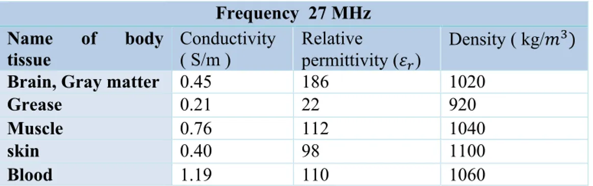
Now we will give certain values of the previous characteristics for a frequency of 27 MHz, 434 MHz, 915 MHz, 1500MHz and 2,45 GHz. Then we will give some important characteristics to choose the best frequency. [12]
Table 1. parameters in frequency 27 MHz Frequency 27 MHz Name of body tissue Conductivity ( S/m ) Relative permittivity (𝜀3) Density ( kg/𝑚5) Brain, Gray matter 0.45 186 1020
Grease 0.21 22 920
Muscle 0.76 112 1040
skin 0.40 98 1100
page 13 de 52
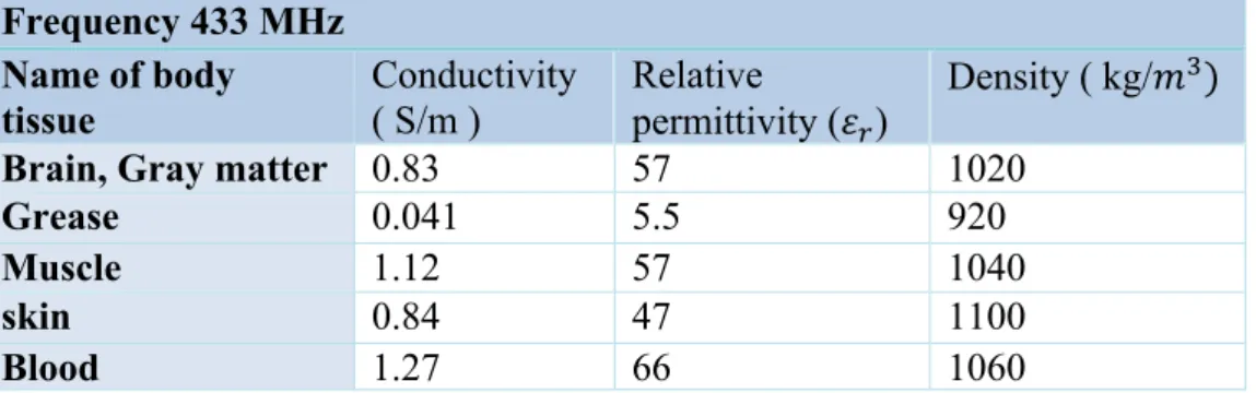
Table 2. parameters in frequency 433 MHz
Table 3. parameters in frequency 915 MHz
Table 4. parameters in frequency 1800 MHz Frequency 433 MHz Name of body tissue Conductivity ( S/m ) Relative permittivity (𝜀3) Density ( kg/𝑚 5) Brain, Gray matter 0.83 57 1020
Grease 0.041 5.5 920 Muscle 1.12 57 1040 skin 0.84 47 1100 Blood 1.27 66 1060 Frequency 915 MHz Name of body tissue Conductivity ( S/m ) Relative permittivity (𝜀3) Density ( kg/𝑚 5) Brain, Gray matter 1 50 1020
Grease 0.35 15 920 Muscle 1.45 55.4 1040 skin 0.97 45 1100 Blood 1.41 62 1060 Frequency 1800 MHz Name of body tissue Conductivity ( S/m ) Relative permittivity (𝜀3) Density ( kg/𝑚5) Brain, Gray matter 1.65 46 1020
Grease 0.105 7.75 920
Muscle 2 55.3 1040
skin 1.2 42 1100
page 14 de 52
Table 5. parameters in frequency 2,45 GH
The Temperature in a human body increase with two parameters: Specific absorption rate and lost energy.
- Specific absorption rate (SAR) is a rate of energy absorption in human body. [9]The measure is the power per mass of tissue (W/kg) but this is normalized by his density. this is the equation:
𝑆𝐴𝑅 = 𝑃 𝜌 =
𝜎 ∙ 𝐸 1 𝜌
𝐸 = rms magnitude of the electric field strength vector (V/m). 𝜌 = tissue density (kg/𝑚5).
𝜎 = conductivity (S/M).
The SAR of a biological organism depends on exposure parameters such as the frequency of radiation, the intensity, the polarization, the configuration of the radiant source and the body, the surfaces of reflection and Size and shape and electrical properties of the body.
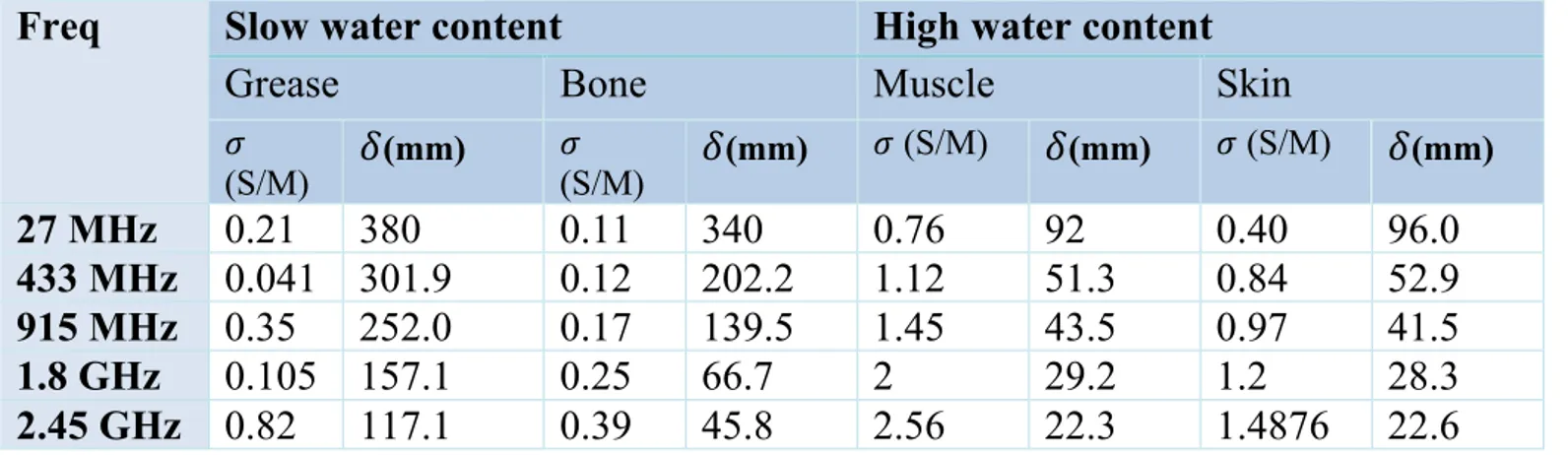
- Depth of penetration (
𝛿
) is defined as the length at which electromagnetic radiation can reach within a material. It is measured in meters or millimetres, depends on the two parameters mentioned above, also on the geometry of the body, the intensity of the radiation, the frequency, etc. [12]𝑝 =
𝜎
𝜔 ∙ 𝜀
3𝛿 𝑑𝑒𝑝𝑡ℎ 𝑜𝑓 𝑝𝑒𝑛𝑒𝑡𝑟𝑎𝑡𝑖𝑜𝑛
= 1 𝜔 𝜇𝜀 2 1 + 𝑝 2 1/2 − 1 1/2 Frequency 2,45 GHz Name of body tissue Conductivity ( S/m ) Relative permittivity (𝜀3) Density ( kg/𝑚 5) Brain, Gray matter 1.43 43 1020Grease 0.82 12 920
Muscle 2.56 49.6 1040
skin 1.4876 44 1100
page 15 de 52
𝜀
3=
permittivity in the vacuum. (F/m)𝜔 = Pulsation or angular frequency of the wave. (rad/s)Escriba aquí la ecuación.
Freq
Slow water content
High water content
Grease
Bone
Muscle
Skin
𝜎 (S/M)
𝛿
(mm) 𝜎 (S/M)𝛿
(mm) 𝜎 (S/M)𝛿
(mm) 𝜎 (S/M)𝛿
(mm)27 MHz
0.21
380
0.11
340
0.76
92
0.40
96.0
433 MHz 0.041 301.9
0.12
202.2
1.12
51.3
0.84
52.9
915 MHz 0.35
252.0
0.17
139.5
1.45
43.5
0.97
41.5
1.8 GHz
0.105 157.1
0.25
66.7
2
29.2
1.2
28.3
2.45 GHz 0.82
117.1
0.39
45.8
2.56
22.3
1.4876
22.6
Table 6. Depth of penetration in different frequencies and body tissues
Normal human body temperature is around 35-37 degrees. This hyperthermia function need to raises the temperature above 40-43 degrees. So we need to increase a certain temperature differential:
∆𝑇 = ℎ𝑦𝑝𝑒𝑟𝑡ℎ𝑒𝑟𝑚𝑖𝑎 𝑡𝑒𝑚𝑝𝑒𝑟𝑎𝑡𝑢𝑟𝑒 − 𝑏𝑜𝑑𝑦 𝑡𝑒𝑚𝑝𝑒𝑟𝑎𝑡𝑢𝑟𝑒 = 40℃ − 36℃ = 4 ℃ approximately
The objective of raising the temperature of the body with microwave waves is due to the characteristics of the human body. The human body and also food contain water, fats and other substances, these elements have molecules that are electric dipoles meaning they have a partial positive charge and a partial negative charge at each end, they rotate because they want to align with the electric field Microwave alternating current. When the molecules are rotated they collide with others and are in movement, this generates heat. This phenomenon is called dielectric heating.
There are different ways of having this dielectric heating in the human body. In addition to the microwave waves that we use in our work, there are also the “short wave”. The “short wave” are high frequency currents between 3 and 300 MHz, these have a heating effect of the tissues that absorb their energy, these waves are in the bands of high frequency and very high frequency.
These "short waves" are divided by how they are generated. Inductive or Capacitive.
The inductive method produces high frequency electrical currents within the body tissue. These currents will increase if the electrical conductivity of the tissue region also increases, such as tissues with good blood circulation.
page 16 de 52 Fig 1. Part of the body with heat by inductive generation
The capacitive field treatments consist of placing the body part with the tumour between two electrodes and using high frequency fields. The transformation of energy into heat takes place mainly in tissues with low blood circulation. Therefore, most of the heat is generated in the areas near the surface of the skin.
Fig 2. Part of the body with heat by capacitive generation
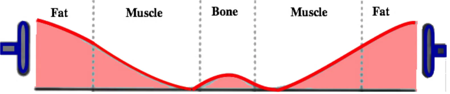
Our antenna uses microwave frequency between 27 MHz and 2,45 GHz. These heat all the muscle evenly without giving too much heat to the skin and deep areas, because microwaves are absorbed by tissues with a high water content.
Fig 3. Part of the body with heat by microwaves
The required power for a maximum temperature threshold of 40-43°C is inversely proportional to peak SAR. The next section, we will obtain the dimensions of different types of antenna for certain frequencies. In this way with all these conclusions we will choose a single frequency and later simulate with the HFSS program.
The last characteristic for antenna is the dimension of this. For this reason, we will make some function with the formulas of antenna theory and show all the results in a table.
page 17 de 52
Antenna theory
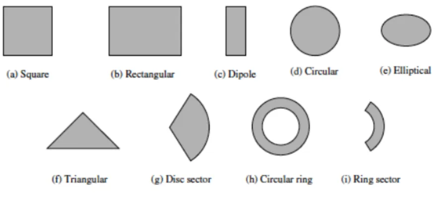
The types of antenna are very varied, but in our work we will focus on a concrete antenna because our laboratory has some limitations for the manufacture. The most common and economical antennas are Microstrip Antennas antennas have characteristic and specifications [9], the most important are substrate and dimensions.
There are numerous substrates that can be used for the design with different range of dielectric constants (2.2 ≤ 𝜖3 ≤ 12) or permittivity , but in the laboratory only have a permittivity substrate (FR4 epoxy) with 𝜖3 = 4.6 and a fixed height of the dielectric layer is 1.5 mm. For this reason, only can change antenna dimension or shape (frequency) to get the most optimal result.
Fig 4. types of antenna
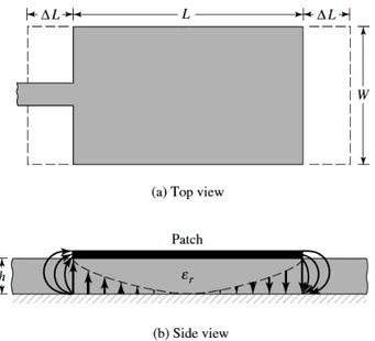
Transmission-Line Model-Rectangular Patch
page 18 de 52 Transmission-Line Model-Rectangular Patch
Based ont he simplified formulation that has been described, a design procedure is outlined which leads to practical designs of rectangular microstrip antennas. The procedure assumes that the specified information includes the dielectric constant of the substrate (𝝐𝒓 ) , the resonant frequency (𝒇𝒓 ) , and the height of the substrate 𝒉.
Fig 6.dimensions of transmission-Line Model-Rectangular Patch
There is the formulation to obtain the parameters 𝑾 and 𝑳 that deepens of frequency.
𝑾 = 𝒗𝟎 𝟐 ∙ 𝒇𝒓 𝟐 𝝐𝒓+ 𝟏 𝑣s= speed of light 𝑓3= resonant frequency
𝜖3= dielectric constant of the substrate
𝝐𝒓𝒆𝒇𝒇 = 𝝐𝒓+ 𝟏 𝟐 + 𝝐𝒓 − 𝟏 𝟐 𝟏 + 𝟏𝟐 𝒉 𝑾 u𝟏/𝟐
𝜖3vww= effective dielectric constant ℎ= height of the substrate
𝑊= antenna width
∆𝑳 = 𝟎. 𝟒𝟏𝟐 ∙ 𝒉 𝜺𝒓𝒆𝒇𝒇+ 𝟎. 𝟑 𝑾𝒉 + 𝟎. 𝟐𝟔𝟒 𝜺𝒓𝒆𝒇𝒇− 𝟎. 𝟐𝟓𝟖 𝑾𝒉 + 𝟎. 𝟖 ∆𝐿= extended incremental length of the patch
page 19 de 52 𝑳𝒆𝒇𝒇 = 𝒗𝒐
𝟐𝒇𝒓 𝜺𝒓𝒆𝒇𝒇
𝐿vww= effective length of the patch 𝑳 = 𝑳𝒆𝒇𝒇− 𝟐 ∙ ∆𝑳
𝑳= length of the patch
𝑳𝒈= 𝟔 ∙ 𝒉 + 𝑳
𝑾𝒈= 𝟔 ∙ 𝒉 + 𝑾
𝒅𝒊𝒇 = 𝑾𝒈− 𝑾 Rectangular microstrip-line feed
The next type of antenna is similar in the calculation of the 𝑾 and the 𝑳, but in this case we add a feed (𝒚𝟎).
Fig 7. dimensions of Rectangular microstrip-line feed
The formulation to obtain the parameters W and L are the same and only obtain the feed.
𝑾 = 𝒗𝟎 𝟐 ∙ 𝒇𝒓 𝟐 𝝐𝒓+ 𝟏 𝝐𝒓𝒆𝒇𝒇 = 𝝐𝒓+ 𝟏 𝟐 + 𝝐𝒓 − 𝟏 𝟐 𝟏 + 𝟏𝟐 𝒉 𝑾 u𝟏/𝟐 ∆𝑳 = 𝟎. 𝟒𝟏𝟐 ∙ 𝒉 𝜺𝒓𝒆𝒇𝒇+ 𝟎. 𝟑 𝑾𝒉 + 𝟎. 𝟐𝟔𝟒 𝜺𝒓𝒆𝒇𝒇− 𝟎. 𝟐𝟓𝟖 𝑾𝒉 + 𝟎. 𝟖 𝑳𝒆𝒇𝒇 = 𝒗𝒐 𝟐𝒇𝒓 𝜺𝒓𝒆𝒇𝒇
page 20 de 52 𝑳 = 𝑳𝒆𝒇𝒇− 𝟐 ∙ ∆𝑳
feed whose characteristic impedance is given by:
𝝀𝟎= 𝒄 𝒇 𝑮𝟏= 𝑰𝟏 𝟏𝟐𝟎𝝅𝟐 𝑰𝟏 = 𝒔𝒊𝒏 𝒌𝟎𝑾𝟐 𝒄𝒐𝒔 𝜽 𝒄𝒐𝒔 𝜽 𝟐 𝒔𝒊𝒏𝟑𝜽 𝝅 𝟎 𝒅𝜽 = −𝟐 + 𝒄𝒐𝒔 𝑿 + 𝑿𝑺𝒊 𝑿 + 𝒔𝒊𝒏 𝑿 𝑿 𝑿 = 𝒌𝟎𝑾
Using modal expansion analysis, the input resistance for the inset feed is given approximately. However, the inset feed introduces a physical notch, which in turn introduces a junction capacitance. The physical notch and its corresponding junction capacitance influence slightly the resonance frequency.
𝑮𝟏=𝟏𝟐𝟎𝝀𝑾 𝟎 𝟏 − 𝟏 𝟐𝟒(𝒌𝟎𝒉) 𝟐 𝒉 𝝀𝟎 < 𝟏 𝟏𝟎 𝑮𝟏𝟐 = 𝟏𝟐𝟎𝝅𝟏 𝟐 𝒔𝒊𝒏 𝒌𝟎𝑾𝟐 𝒄𝒐𝒔𝜽 𝒄𝒐𝒔𝜽 𝟐 𝑱𝟎 𝒌𝟎𝑳 𝐬𝐢𝐧 𝜽 𝒔𝒊𝒏𝟑𝜽 𝒅𝜽 𝝅 𝟎 aproximadle 0
the desired impedance (𝑹𝒊𝒏) is 50 ohms, the inset feed point distance 𝒚𝟎 is obtained using:
𝑹𝒊𝒏 = 𝟏
𝟐 𝑮𝟏± 𝑮𝟏𝟐 𝒄𝒐𝒔𝟐 𝝅 𝑳𝒚𝟎
Circular path
Other than the rectangular patch, the next most popular configuration is the circular patch or disk. Therefore, the order of the modes can be changed by changing the relative dimensions of the width and length of the patch (width-to-length ratio). However, for the circular patch there is only one degree of freedom to control (radius of the patch). Doing this does not change the order of the modes; however, it does change the absolute value of the resonant frequency of each.
page 21 de 52 Fig 8. dimensions of circular patch antenna
Similarly for the circular patch a correction is introduced by using an effective radius, given by:
𝐹 =8.791 ⋅ 10œ 𝑓3⋅ 𝜖3 (𝑐𝑚) 𝑎 = 𝐹 1 + 2 ∙ ℎ𝜋 ∙ 𝜖 3∙Ÿ ∙ 𝑙𝑛 𝜋 ∙ 𝐹2ℎ + 1.7726 ¡/1 𝑎 = antenna radius Cavity model-Circular patch
Another type of antenna that we will only give theorical information without any calculation. Initially, the antenna evolved from a circular patch to an annular ring patch antenna. The circular patch antenna presents a fundamental resonant frequency of:
𝑓 = 1.8412 ∙ 𝐶s 2 ∙ 𝜋 ∙ 𝑎v∙ 𝜀3
𝐶s= speed of the light in the vacuum 𝜀3 = dielectric constant of the substrate h = substrate thickness (cm)
𝑎v = the effective radius to account the fringing that makes the patch look electrically larger 𝑎£¤= physical radius of the circular patch (cm
)
𝑎
v= 𝑎
£¤1 +
2ℎ
𝜋 ∙ 𝑎
£¤∙ 𝜀
3𝑙𝑛
𝜋 ∙ 𝑎
£¤2ℎ
+ 1.7726
page 22 de 52 𝜀3vww_¦§§_3¨§© = effective dielectric constant
𝑎ª«¤ = inner radius of the antenna 𝑏ª«¤= outer radius of the antenna
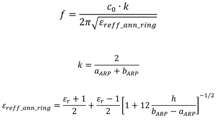
The fundamental resonance frequency for the annular ring patch antenna can be calculated with:
𝑓 =
𝑐
s∙ 𝑘
2𝜋 𝜀
3vww_¦§§_3¨§© 𝑘 = 2 𝑎ª«¤+ 𝑏ª«¤ 𝜀3vww_¦§§_3¨§© = 𝜀3+ 1 2 + 𝜀3− 1 2 1 + 12 ℎ 𝑏ª«¤− 𝑎ª«¤ u¡/1Measurements with SAR and power theory
The power levels used for the three different major body (epigastric, inter-scapular and head location) are related to SAR. We need to know the peak SAR in three parts of the body where we will measure, because this peak is inversely proportional to power for a maximum temperature threshold of 43°C. The SAR limit is 2 W/kg in 10 grams of tissues, if this valour increase also the temperature increase too. [13]
Peak SAR (W/kg ) 1/𝒆𝟐 SAR penet. (mm)
Epigastric 6.14 56
Head 6.41 53
Inter – scapular 5.28 60
Fig 9. Peak SAR penetrations for the homogeneous muscle
The required power source for the different locations and there is a linear relation between peak SAR and required power, approximately:
- epigastric (peak SAR = 6.14W/kg, required power = 78 W) - head (peak SAR = 6.41 W/kg, required power = 75 W)
- inter-scapular location (peak SAR = 5.28 W/kg, required power = 92 W)
page 23 de 52
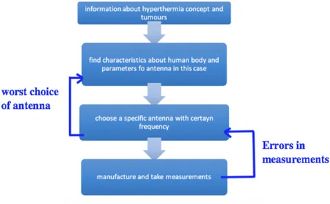
III. Project development
General scheme of project development. This diagram is generally process step by step with modifications to another back if results are not correctly.
Fig 10. scheme of project development
The previous theory "Properties, models electromagnetics of the human body and bands of frequency" gives us information for important parameters to obtain a certain antenna. The table show some valour’s about permittivity and conductivity in human body changing with frequencies.
When the frequency is more high:
Conductivity
page 24 de 52
We are calculated SAR and depth of penetration with some suppositions (𝐸=1) and the valour’s of tables in theory work of permittivity, density and conductivity.
%%%%%%%%calc%%%%%%%%%% %%%%%%%%SAR%%%%%%%%%%%% SAR_27_skin=(cond_skin_27*abs(E)^2)/(dens_skin) SAR_27_grease=(cond_grease_27*abs(E)^2)/(dens_grease) SAR_27_muscle=(cond_muscle_27*abs(E)^2)/(dens_muscle) SAR_27_blood=(cond_blood_27*abs(E)^2)/(dens_blood) SAR_433_skin=(cond_skin_433*abs(E)^2)/(dens_skin) SAR_433_grease=(cond_grease_433*abs(E)^2)/(dens_grease) SAR_433_muscle=(cond_muscle_433*abs(E)^2)/(dens_muscle) SAR_433_blood=(cond_blood_433*abs(E)^2)/(dens_blood) SAR_915_skin=(cond_skin_915*abs(E)^2)/(dens_skin) SAR_915_grease=(cond_grease_915*abs(E)^2)/(dens_grease) SAR_915_muscle=(cond_muscle_915*abs(E)^2)/(dens_muscle) SAR_915_blood=(cond_blood_915*abs(E)^2)/(dens_blood) SAR_1800_skin=(cond_skin_1800*abs(E)^2)/(dens_skin) SAR_1800_grease=(cond_grease_1800*abs(E)^2)/(dens_grease) SAR_1800_muscle=(cond_muscle_1800*abs(E)^2)/(dens_muscle) SAR_1800_blood=(cond_blood_1800*abs(E)^2)/(dens_blood) SAR_2450_skin=(cond_skin_2450*abs(E)^2)/(dens_skin) SAR_2450_grease=(cond_grease_2450*abs(E)^2)/(dens_grease) SAR_2450_muscle=(cond_muscle_2450*abs(E)^2)/(dens_muscle) SAR_2450_blood=(cond_blood_2450*abs(E)^2)/(dens_blood)
SAR
Frequency
Skin
Grease
Muscle
Blood
27 MHz
3.6364e-04 2.2826e-04 7.3077e-04 0.0011433 MHz
7.6364e-04 4.4565e-05 0.0014 0.0013915 MHz
8.8182e-04 3.8043e-04 0.0014 0.00131800 MHz
0.0011
1.1413e-04
0.0019
0.0012
2.45 GHz
0.0014 8.9130e-04 0.0025 0.0019page 25 de 52
The conductivity of the body tissues increases with frequency, and consequently for the same radiation power the SAR increases for higher frequencies. Frequency band (27 MHz- 2.45 GHz), the body can absorb energy in a localized way, this absorption decreases with frequency. The absorbed energy is a function of the frequency of operation, incident E-field, and dielectric properties of the tissue. The lost energy is a function of the generated blood flow in the tissue and the conduction of heat.
Conclusions:
- bone and fat are bad conductors so they absorb energy weakly and the radiofrequency signal penetrates deeply into the tissues.
- High water content in tissues such as muscles and skin are good conductors and these are more strongly absorbed energy.
- At higher frequencies the depth of the skin decreases. The absorption in the body becomes increasingly limited to the surface of the tissues.
- The hyperthermia function is better in 1800 MHz and 915MHz, the reason is these frequencies have more depth penetration than 2.45 GHz but more less SAR. The next characteristics give more information about which antenna use in one case or another.
We have performed a Matlab function (Antcal (), Antcal_rectfeed () and Antcal_circ() ) with the formulas previously used. See appendix A :
The matlab functions created for the different cases, give this result of the following tables:
Frequency Size
Transmission-Line Model-Rectangular
Patch Rectangular microstrip-line feed 27 MHz (W=3201mm,L=2589mm ) Area = 8.287.389 𝒎𝒎 𝟐 (W=33201mm,L=2589mm, y0=864mm) Area =8.287.389 𝒎𝒎 𝟐 433 MHz (W=207mm,L=157mm) Area = 𝟑𝟐𝟒𝟗𝟗 𝒎𝒎𝟐 (W=207mm,L=157mm, 52.4mm) Area = 𝟑𝟐𝟒𝟗𝟗 𝒎𝒎𝟐 915 MHz (W=98mm,L=70.1mm) Area =6.869,8 𝒎𝒎𝟐 (W=98mm,L=70.1mm, 23.4mm) Area = 𝟔. 𝟖𝟔𝟗, 𝟖𝒎𝒎𝟐 1.8 GHz (W=49.8mm,L=31.2mm) Area =1553,6 𝒎𝒎𝟐 (W=49.8mm,L=31.2mm, y0=10.4mm) Area =1553,6 𝒎𝒎𝟐 2.45 GHz (W=36.6mm,L=20.5mm) Area =750,3 𝒎𝒎𝟐 (W=36.6mm,L=20.5mm, 6.8mm) Area =750,3 𝒎𝒎𝟐 Table 8. results of matlab functions at different frequencies
page 26 de 52
Frequency Size
Circular path Cavity model-Circular patch 27 MHz (R=1551 mm) Area = 7557418.43 𝒎𝒎𝟐
433 MHz (R=96 mm) Area = 28952.92 𝒎𝒎𝟐 915 MHz (R=43.4 mm) Area = 5917.38 𝒎𝒎𝟐 1.8 GHz (R=22.7 mm) Area = 1618.83 𝒎𝒎𝟐 2.45 GHz (R=16.6 cm ) Area= 865.7 𝒎𝒎𝟐 Table 9. results of matlab functions at different frequencies
The size of the antenna is higher when the frequencies is smaller. For this reason, we will choose circular antennas in frequencies of 915 MHz and 1.8 GHz, because these are smaller than another models. These two frequencies are best for performing the function of hyperthermia, it depends what part of the body we use. 915 MHz antenna is higher than 1.8 GHz but have more quality of SAR and depth of penetration, this is god in two parts of the body:
Fig 11. Inter scapular Region Fig 12. Epigastric Region
Antennas in frequencies of 915 MHz:
- For example in epigastric region have sarcoma tumours that originate in the muscular elements: leiomyosarcoma, fibrosarcoma and rhabdomyosarcoma (explain in introduction).
- Lipomas are frequently in Inter Scapular Region.
page 27 de 52
3 Simulation with HFSS
HFSS is program that can I find in laboratory pcs and work , this program have finite element method solver for electromagnetic structures from ANSYS. It is one of several commercial tools used for antenna design, and the design of complex RF electronic circuit . The theory work I came to the conclusion that the antennas of circular type for the two frequencies of 915 MHz and 1.8GHz are the best case. For this reason, we will simulate these two antennas with HFSS to see the results.
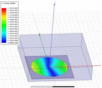
Fig 13. Circular patch antenna frequency 915MHz with HFSS
page 28 de 52
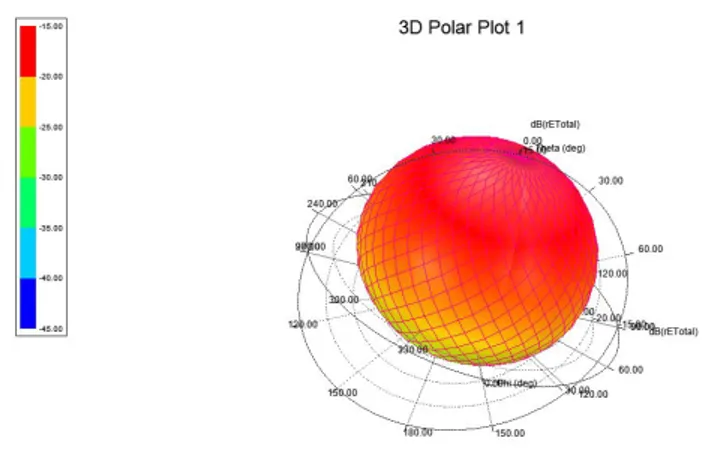
The simulation gives us a 3D graph of the electric field; we can see that the electric field (rE Total) has a range of -15 to -45 dB. So we have a maximum of -15 dB
Fig 15. E total (dB) in 3D for circular patch antenna frequency 915MHz with HFSS
Fig 16. Circular patch antenna frequency 1800 MHz with HFSS
page 29 de 52
Fig 18. E total (dB) in 3D for circular patch antenna frequency 1800MHz with HFSS
The simulation gives us a 3D graph of the electric field; we can see that the electric field (rE Total) has a range of -5 to -35 dB. So we have a maximum of -5 dB. The E field is the electric field strength in the direction of maximum radiation. The different antennas have difference of -10 dB. The antenna in 1800 MHz frequency have more power ratio than the another.
4 Design with ADS
We use the program ADS of the laboratory or remote application of HIG. The reason is a simple program that you can work on or draw on a layout, then you can see the main features such as parameters 𝑠¡¡ or the electromagnetic field in 3D.
In this step we will design the three types of antennas for the two different frequencies 915 MHz and 1800 MHz, but we are only going to manufacture circular patch antenna. The program uses measures in mil. For this reason, we will convert the Table 8 and Table 9 with this web program:
Fig 19. web converter mil to mm
page 30 de 52
Circular antenna design to 915 MHz
Fig 20. layout antenna circular 915 MHz
page 31 de 52
Circular antenna design to 1800 MHz
Fig 22. layout antenna circular 1800 MHz
Fig 23. parameters S_11 antenna circular 1800 MHz
The figures of parameters S_11 antenna circular in frequencies 915 MHz and 1800MHz show the power relationship with frequencies.
- Circular antenna in frequency 915 MHz have -3,6 dB of power - Circular antenna in frequency 1800 MHz have -4,6 dB of power
The frequency antenna 915 MHz has the best power output that the other but the difference is small. These two types of antenna with different frequencies are choice for manufacture and tested.
page 32 de 52
Manufacturing
Making the antenna is simple when we already have the files created with ADS, we only need to import them and follow a few steps in CircuitPro software. The next step is to calibrate the machine with the substate "lpkf protomat e34" and late change this with the different measurements. The last step is weld SMA connector in the substrate.
Fig 24. LPKF protomat e34
Budget
The cost of this project will be 455 euros (with VAT) due to the sum of the components plus labour or workforce.
The component FR4 substrate plate of size D-A4 LPKF Brand have a price of 10 euros and one SMA connector have 5 euros. The labour of a technician work (4∙ 30 + 𝑉𝐴𝑇 =140 euros) and 4 hours of rental of measuring and manufacturing equipment (300 euros). Manufacture a specific component or antenna for a characteristic part of the body is expensive.
page 33 de 52
Analysis of results
Measurements
When evaluating the antenna for different types of tumours, we have to consider the conductivity and density ratios indicate absorption rates throughout the body, other factors should be considered. Factors such as tissue volumes or organ forms. Measurements will be obtained with laboratory antennas working at a frequency of 2.45 GHz (the worst case within the IMS band) in this case the RF increase temperature although it is the worst option. This frequency is the same as that used in microwave ovens but these use more power than our laboratory instruments. The disadvantage of this frequency as mentioned above is the low of depth penetration and SAR.
Now we will make an experiment. The laboratory consists of this instruments of measurement and power generation
Fig 25. vector signal generator Fig 26. temperature sensor
The vector signal generator has a limit voltage and therefore also of power. We will input this maxim limit in this instrument, this is 30dBm (1 W). In real life we would need higher power ranges to perform in perfect conditions the hyperthermia function. Later we will talk about these ranges and the relation with SAR.
page 34 de 52
The tests are done with a piece of meat raising the temperature of the meat with water. We waited for more than an hour until the temperature stabilized and not lower more, this temperature is 16.6 ºC. The meat and antenna are distance of 5 cm:
Fig 27. meat temperature without vector signal generator
The next step is turn ON the vector signal generator and wait. After of 6 minutes approximately (5 min 34 sec) and see how the temperature increase 0.1 ºC, but not more of this temperature.Can see in the next pictures:
page 35 de 52
We observe the result and this can’t increase more his value, we turn off the machine and wait to decrease the temperature, approximately. This process is repeated two times again to support more our experiment. The previous result is repeated again but with different times:
↑ 𝟎. 𝟏℃ ↓ 𝟎. 𝟏℃
First time 5 min 34 sec 15 min 10 sec
Second time 7 min 40 sec 16 min 60 sec
Third time 6 min 10 sec 14 min 10 sec
Table 10.Experiment times
The experiment is done with the worst case antenna and we came to the conclusion that we need 1 W to increase 0.1. Measurements and power theory say that antenna need powers between 70-90 W to increase 4ºC depends part of the body. The experiment would correctly use the antenna between our different parts of the body and the sensor, use higher levels of power and see how it increases the temperature of tissue.
An important improvement could be the use of a waterbolus, this interfere the skin of the exposed body region is used to cool the body surface and for improved antenna coupling. With this modification in our antenna we should take into account again the characteristics like the SAR or the depth of penetration, most important is depth of penetration because we have to choose a certain frequency. Volume and surface wave oscillations are generated inside the waterbolus if the thickness of the waterbolus exceeds a frequency dependent value. For this case the best antenna is rectangular feed or circular at 915 MHz.
In clinical trials the water circulates in a temperature controlled system and in this work values are
reported for a water temperature of 27°C. So another factor would be the temperature variation, since now the waterbolus has a lower temperature and for this reason should be increased even more power. The last is the shape of the antenna together with the waterbolus.
page 36 de 52
IV. Conclusion
This project reveals the different cases (tumours and zones) where we can use the concept of hyperthermia. The main objective has been to discover the main characteristics (SAR and depth of penetration) to know which antenna to use and for which case. The antenna has to be in the frequency range IMS (Industrial Scientific and Medical frequencies), as an optimal result we have the antennas of 915 MHz or 1800 MHz, one for larger body sites (Epigastric Region and Inter Scapular Region) and the other for more specific sites (head), this is determined by the size. Finally, we have seen how the microwave frequencies can heat an organic object; we have also found the approximate power values to obtain a good result in the heating. The work might have determined on the measures part by choosing a frequency between the IMS range for example, make measurements with a device that do 70-100 W to obtain the “best characteristic power” with a unique antenna and obtain our own conclusions, but this in not own thesis project.
We only do the technical part of obtaining the best antenna based on the medical part and parameters. Doctor should check the type of tumour (liquid or solid) more exhausted to determine if the next treatment may be good or not, or this treatment can also be combined with chemotherapy.
page 37 de 52
Appendix
Appendix A
E=1; dens_brain=1020; dens_grease=920; dens_muscle=1040; dens_skin=1100; dens_blood=1060; %%%%%%27MHz%%%%%% cond_brain_27=0.45; cond_grease_27=0.21; cond_muscle_27=0.76; cond_skin_27=0.40; cond_blood_27=1.19; perm_brain_27=186; perm_grease_27=22; perm_muscle_27=112; perm_skin_27=98; perm_blood_27=110; %%%%%%433MHz%%%%%% cond_brain_433=0.83; cond_grease_433=0.041; cond_muscle_433=1.12; cond_skin_433=0.84; cond_blood_433=1.27; perm_brain_433=57; perm_grease_433=5.5; perm_muscle_433=57; perm_skin_433=47; perm_blood_433=66; %%%%%%915MHz%%%%%% cond_brain_915=1; cond_grease_915=0.35; cond_muscle_915=1.45; cond_skin_915=0.97; cond_blood_915=1.41; perm_brain_915=50; perm_grease_915=15; perm_muscle_915=55.4; perm_skin_915=45; perm_blood_915=62; %%%%%%1800MHz%%%%%% cond_brain_1800=1.65; cond_grease_1800=0.105; cond_muscle_1800=2; cond_skin_1800=1.2; cond_blood_1800=1.25;page 38 de 52 perm_brain_1800=46; perm_grease_1800=7.75; perm_muscle_1800=55.3; perm_skin_1800=42; perm_blood_1800=62.3; %%%%%%2450MHz%%%%%% cond_brain_2450=1.43; cond_grease_2450=0.82; cond_muscle_2450=2.56; cond_skin_2450=1.4876; cond_blood_2450=2.04; perm_brain_2450=43; perm_grease_2450=12; perm_muscle_2450=49.6; perm_skin_2450=44; perm_blood_2450=60; >> SAR SAR_27_skin = 3.6364e-04 SAR_27_grease = 2.2826e-04 SAR_27_muscle = 7.3077e-04 SAR_27_blood = 0.0011 SAR_433_skin = 7.6364e-04 SAR_433_grease = 4.4565e-05 SAR_433_muscle =
page 39 de 52 0.0011 SAR_433_blood = 0.0012 SAR_915_skin = 8.8182e-04 SAR_915_grease = 3.8043e-04 SAR_915_muscle = 0.0014 SAR_915_blood = 0.0013 SAR_2450_skin = 0.0014 SAR_2450_grease = 8.9130e-04 SAR_2450_muscle = 0.0025 SAR_2450_blood = 0.0019 >> SAR SAR_27_skin = 3.6364e-04
page 40 de 52 SAR_27_grease = 2.2826e-04 SAR_27_muscle = 7.3077e-04 SAR_27_blood = 0.0011 SAR_433_skin = 7.6364e-04 SAR_433_grease = 4.4565e-05 SAR_433_muscle = 0.0011 SAR_433_blood = 0.0012 SAR_915_skin = 8.8182e-04 SAR_915_grease = 3.8043e-04 SAR_915_muscle = 0.0014
page 41 de 52 SAR_915_blood = 0.0013 SAR_1800_skin = 0.0011 SAR_1800_grease = 1.1413e-04 SAR_1800_muscle = 0.0019 SAR_1800_blood = 0.0012 SAR_2450_skin = 0.0014 SAR_2450_grease = 8.9130e-04 SAR_2450_muscle = 0.0025 SAR_2450_blood = 0.0019 function Antcal_rect()
%This function is to be used to calculate the different parameters of a %rectangular path antenna
clc;
% 0.95 GHz - 2.45 GHz fo=;
page 42 de 52 Er=4.6; h=1.5e-3; W=(3*10^8)/(2*fo*sqrt((Er+1)/2)) Eref=(Er+1)/2+((Er-1)/2)/(sqrt(1+12*h/W)) Lef=(3*10^8)/(2*fo*sqrt(Eref)) dL=((0.412*h)*(Eref+0.3)*(W/h+0.264))/((Eref-0.258)*(W/h+0.8)) L=Lef-2*dL Lg=6*h+L Wg=6*h+W dif=Wg-W function Antcal_rectfeed()
%This function is to be used to calculate the different parameters of a %rectangular feed path antenna
clc; % 0.95 GHz - 2.45 GHz fo=2.45*10^9; Er=4.6; h=0.015; c=3*10^8; lambda0= c/fo; k0=(2*pi)/(lambda0); W=(3*10^8)/(2*fo*sqrt((Er+1)/2)) Eref=(Er+1)/2+((Er-1)/2)/(sqrt(1+12*(h/W))); Lef=(3*10^8)/(2*fo*sqrt(Eref)); dL=(0.412*h)*(((Eref+0.3)*((W/h)+0.264))/((Eref-0.258)*((W/h)+0.8))); L=Lef-2*dL %G1=(W/(120*lambda0))*(1-(1/24)*((k0*h)^2)) G1=(1/120)*(W/lambda0) %50=(1/(2G1))*cos((pi*y0)/(L))^2 y0=((acos(sqrt(50*G1*2)))*L)/(pi) function Antcal_circ()
%This function is to be used to calculate the different parameters of a %circular path antenna
clc; % 0.95 GHz - 2.45 GHz fo=; Er=4.6; h=1.5e-3; F=(8.791*10^9)/(fo*sqrt(Er)) %%%ratio of antenna%%%
page 43 de 52
a=(F)/(1+((2*h)/(pi*Er*F))*(ln((pi*F)/(2*h))+1.7726))^1/2
Appendix B
Fig 29.parameters S_11 circular antenna 1800 MHz with HFSS
page 44 de 52
Fig 31. layout antenna rectangular 915 MHz
page 45 de 52
Fig 33.layout antenna rectangular feed 915 MHz
page 46 de 52
Fig 35. layout antenna circular 1800 MHz in 3D with A/m
page 47 de 52
Fig 37. layout antenna rectangular 1800 MHz
page 48 de 52
Fig 39. layout antenna rectangular 1800 MHz in 3D with A/m
page 49 de 52
Fig 41. layout antenna rectangular feed 1800 MHz
page 50 de 52
Fig 43. layout antenna rectangular feed 1800 MHz in 3D with A/m
page 51 de 52
References
[1] Ingeniería de microondas técnicas experimentales . José Miguel Miranda , 2002
[2] An UWB Antenna Array for Breast Cancer Detection . master thesis, Sayad Arafath Ruzdiana ,
2011
[3] Caracterización y mejora de equipo para hipertermia magnética. trabajo final grado , Beatriz
Leon Dominguez, 2016
[4] Dual- mode antenna design microwave imaging and microwave heating: experimental simulation of detection and treatment of tumour with hyperthermia. Pan American health care exchanges, 2012 [5] Ondas electromagneticas . Conceptos basicos. Universidad de Cordoba, 2010
[6] Robbins Pathologic Basis of disease, Ramzi Cotran , 1999
[7] Therapeutic applications of electromagnetic power. Guy, AW; Lehmann, JF; Stonebridge, 1974 [8] Alpha-dispersion in human tissue. Dept. of Physics, Univ. of Oslo, Norway . Sverre Grimnes,
Ørjan G Martinsen
[9]Microstrip Patch Antennas. World Scientific.. Lee, Kai Fong,; Luk, Kwai Man , 2011. [10]Antenna Theory. A Balanis. 1976.
[11] Fundamentos fisicos de los procesos biologicos. Fernando Cussó Pérez. 2013 [12] Efectos biológicos de los campos electromagnéticos
[13] Trabajo fin de master: efectos radiaciones no ionizantes en el cuerpo humano. Víctor Manuel
Febles Santana. 2015
[14] Worst case temperature rise in a one-dimensional tissue model exposed to radiofrequency radiation. T. Samaras, A. Christ, A. Klingenbock, and N. Kuster. 2007