Master of Science Thesis
(D-level)
Petr Štěpán
An extensible attribute framework for ProCom
Mälardalen Research and Technology Centre Thesis supervisors: Séverine Sentilles, Jan Carlson
Thesis examiner: Ivica Crnkovic
{severine.sentilles,jan.carlson,ivica.crnkovic}@mdh.se
I would like to express my thanks to supervisors of my thesis, Séverine Sentilles and Jan Carlson, for fruitful discussions about my work and their numerous suggestions for its improvement as well as for their helpfulness in organizational matters.
I also wish to thank Tomáš Bureš for opening up the opportunity for writing my thesis at Mälardalen University.
Abstract
This thesis is focused on the attributes concept of ProCom, a component model developed within The Progress Centre for Predictable Embedded Software Systems. Attributes are pieces of information of various types and levels of abstraction associated with the ProCom entities during the development of a system.
Based on the analysis of the development process envisioned by Progress, the requirements for the attributes of ProCom entities are identified, and various alternatives of realizing attributes are analyzed. The chosen solution of highly structured, multi-valued, and extensible attributes is elaborated.
The thesis also consists of the design and the prototype implementation of an attribute framework realizing and proving the feasibility of the proposed concepts. The framework ad-dresses the needs of all actors involved in working with attributes throughout the development of a system: It provides an extensible, modular GUI for viewing and editing possibly highly complex information contained in attributes, an interface for the programmatic access to at-tributes, and well-defined mechanisms for extending the attribute pool by new atat-tributes, new attribute types, and means for their manipulation. The framework is integrated into the main tool supporting the Progress development, the Progress IDE.
Contents
1 Introduction 1
1.1 Goals of the thesis . . . 2
1.2 The structure of the thesis . . . 2
2 Background 3 2.1 Theoretical background . . . 3 2.1.1 Embedded systems . . . 3 2.1.2 Component-based development . . . 4 2.1.3 Progress . . . 5 2.1.4 ProCom . . . 6 2.2 Technological background . . . 7 2.2.1 Eclipse Platform . . . 7 2.2.2 Progress IDE . . . 9
2.2.3 Eclipse Modeling Framework . . . 9
3 Problem Analysis 11 3.1 Attributes in the development process envisioned by Progress . . . 11
3.2 General attribute requirements . . . 12
3.3 Actors working with attributes . . . 13
3.4 Requirement specification . . . 14
3.4.1 Common attribute requirements . . . 14
3.4.2 Terminology clarification . . . 15
3.4.3 IDE users requirements . . . 15
3.4.4 Module developers requirements . . . 16
3.4.5 Attribute contributors requirements . . . 17
3.5 Use cases . . . 18
3.5.1 Use cases associated with an IDE user . . . 18
3.5.2 Use cases associated with an IDE module developer . . . 19
3.5.3 Use cases associated with an attribute contributor . . . 19
4 Solution Design 20 4.1 Integration with the ProCom metamodel . . . 20
4.2 Attribute structure . . . 21
4.3 Attribute value structure . . . 23
4.3.1 Conceptual structure . . . 23
4.3.2 The implemented design . . . 24
4.3.3 Rejected alternative designs . . . 26
4.3.4 Possible alternative solution: Named extensible metadata . . . 30
4.4 Type extensibility . . . 30
4.4.1 EMF-based methods . . . 31
4.4.2 Externally serialized data . . . 32
4.5 GUI . . . 32
4.5.1 Attribute View . . . 33
4.5.2 Editors and viewers . . . 35
4.5.3 Help . . . 37
4.6 Client API . . . 38
4.7 SPI . . . 39
CONTENTS
4.7.2 Attribute specification . . . 41
5 Prototype description 43 5.1 Scope . . . 43
5.2 Implementation overview . . . 45
5.2.1 The framework core plugin . . . 45
5.2.2 The framework GUI plugin . . . 46
5.3 Demonstration . . . 47
5.3.1 Attribute contribution . . . 47
5.3.2 Prototype GUI . . . 50
6 Conclusion 54
List of Figures
2 Background
1 ProSys subsystems communicating using a message channel [14] . . . 6
2 ProSave components realizing a ProSys subsystem . . . 7
3 Eclipse Platform architecture . . . 8
3 Problem Analysis 4 Various information included in component’s attributes . . . 13
5 Actors in the attribute framework and their associated use cases . . . 18
4 Solution Design 6 Attributableand its role in the attribute metamodel . . . 21
7 Main entities forming an attribute . . . 22
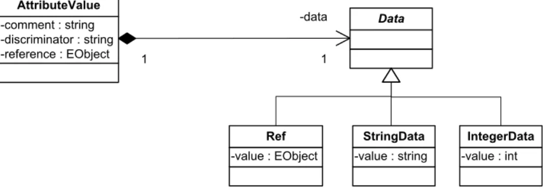
8 Attribute value structure . . . 24
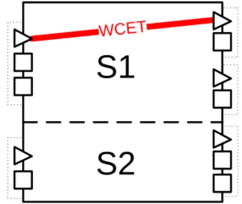
9 Attribute of the worst-case execution time (WCET) between two groups of a service 26 10 All-in-one attribute design exhibiting redundancy . . . 27
11 Attribute design leading to type definition language . . . 27
12 Combining data in an attribute value using multiple inheritance . . . 28
13 Extensible metadata in attribute value combined using composition . . . 29
14 Recursive attributes design . . . 29
15 Named extensible metadata design . . . 30
16 Displaying attribute values comprising of extensible metadata . . . 34
17 Displaying attribute values having fixed metadata . . . 34
18 Interfaces for attribute editors . . . 36
19 Interfaces for attribute viewers . . . 37
20 The client API implemented by the ValueProvider class . . . 38
21 Attribute value proxies . . . 39
22 Sample extension of the attribute contribution extension point . . . 40
5 Prototype description 23 A simplified code of the validator . . . 47
24 A simplified code of the reference provider . . . 48
25 Contribution mark-up for the WCET between two port groups of a service . . . 48
26 Simplified implementation of the image data type . . . 49
27 Serialization support for the ImageData class . . . 50
28 Viewer displaying an image in an external application . . . 50
29 Integration of the Attribute View and the model editor . . . 51
30 The Attribute View . . . 51
31 Managed attribute viewer (the bitmap image viewer) . . . 52
32 Various types of attribute editors . . . 52
Chapter 1
Introduction
In recent years the role of embedded systems1 has grown. They surround us in our lives,
often unnoticed in almost every electronic device we use. They can be found in consumer electronics, safety and control systems in vehicles, telecommunication, industrial automation, medical, robotics, military and many other systems [13].
In 1996 it was estimated that an average American came into contact with 60 microprocessors a day [13]. However, due to improving technologies and dramatical decreases in hardware prices, smaller and at the same time more capable devices are unceasingly coming to the market in greater numbers. This ubiquitous proliferation of embedded systems moves us to the
post-PC era, where more and more information processing is being performed by embedded systems
distributed in our surroundings rather than in our PCs. In the light of these facts, the statement of the journalist Mary Ryan does not seem so much exaggerated:
... embedded chips form the backbone of the electronic world in which we live ...
Despite the growing proliferation of embedded systems, their development is a challenging task since they are required to meet many strict resource limitations in terms of performance, consumed energy and space. Especially in the domain of control-intensive systems, where the cost of a system failure is significant or even critical due to their interaction with the physical world, embedded systems have to be dependable (correct, reliable, robust, high-performing, etc), often working under tight real-time constraints. All of the aforementioned requirements are reflected in the development of these software systems, where low resource consumption and for-mally proved correctness are of a major importance leading to monolithic, platform-oriented, not reusable and hardly maintainable software systems. Embedded system development is starting to become the bottleneck of their further growth in terms of increasing complexity of systems and its high cost.
Progress, a Swedish national research centre for applied research in development of pre-dictable embedded software, has been established to devise theories and techniques dealing with the complexity of embedded systems and their development. The approach taken by Progress consists in employing the well-known development paradigm of component-based development (CBD) successfully applied in other areas of software. However, CBD process has to be ad-justed to the specifics and hard requirements of embedded systems; new procedures, methods and appropriate tools have to be devised and implemented.
One of the cornerstones of the Progress approach is a component model, called ProCom (Progress Component Model), whose design reflects the needs of development process proposed by Progress and which provides the framework supporting the other key activities emphasized by Progress: analysis, verification and deployment. All these activities demand some infor-mation to be associated with components, serving as their inputs or outputs. This feature of
1
Embedded systems are information processing systems performing a limited set of specialized operations, usually being part of some bigger devices (ergo embedded).
CHAPTER 1. INTRODUCTION 1.1. GOALS OF THE THESIS
the component model is furnished by the attributes concept. This thesis should elaborate the notion of an attribute in ProCom by designing its structure and refining its semantics.
However, the development process envisioned by Progress and supported by ProCom is so complex that it is not feasible without proper and massive tool support. Therefore, one of the goals of Progress lies in developing an integrated development environment, called Progress IDE, providing this tool support. It is intended to be an integration platform, where various tools and methods coming from the Progress research should be incorporated to become an ultimate tool backing up the whole development process.
Consequently, this thesis also proposes the design and implementation of an attribute frame-work integrated into the Progress IDE. The frameframe-work aims at providing IDE users with a comfortable means for viewing and modifying component attributes of various types of infor-mation, accumulated throughout their development. Furthermore, the framework is extensible to support adding of new attributes and new attribute types since these are expected to arise frequently as another methods and tools will be developed within Progress.
1.1
Goals of the thesis
Briefly, the goal of this thesis is to propose an attribute framework for the ProCom component model and prove the devised concepts in a prototype integrated into the Progress IDE. Looking closer, there are two main sub-goals comprising the overall goal.
The first one lies in defining the structure of attributes in ProCom based on the analysis of the needs of different stakeholders involved in the development process envisioned by Progress, extending ProCom to support these attributes and devising methods of adding new attributes and attribute types.
The second one relates to the prototype implementation of the attribute framework. The main actors working with attributes should be identified as well as their requirements imposed on the interface of the attribute framework. Their needs should be reflected in the design of interfaces exposed by the framework, which should then be implemented and integrated into the Progress IDE.
1.2
The structure of the thesis
The structure of this document is the following. A brief introduction to the theories forming the context of this thesis together with the technologies used during its implementation part are presented in Chapter 2. The following two chapters represent the main contribution of the thesis. Chapter 3 gathers the main actors and key requirements for the properties of ProCom attributes and working with them. The designs realizing these requirements are elaborated and discussed compared to their alternatives in Chapter 4. Chapter 5 briefly describes the prototype implementation in terms of its scope and main features illustrating the main concepts on sample attribute additions. The whole thesis is concluded in Chapter 6, where the contribution of the thesis is assessed and the possible future improvements are suggested.
Chapter 2
Background
In this chapter the theories and technologies forming the context of thesis are briefly summarized. Embedded systems, component-based development, Progress and ProCom are introduced in the theoretical background. The technological background consists of concise descriptions of the Eclipse Platform, the Progress IDE and Eclipse Modeling Framework.
2.1
Theoretical background
2.1.1 Embedded systems
‘Embedded systems are information processing systems that are embedded into a larger product.’ [13] Nowadays, they can be found in a great variety of electronic devices ranging from consumer electronics (MP3 players, calculators, microwave ovens, etc.) to traffic lights controllers, vehic-ular control systems and systems controlling nuclear power plants. Despite the diversity of this class of systems some common characteristics exist [13]:
• Typically, they interact with and control the physical environment they are embedded in. • There is the strong need for dependability of these systems, which is caused mainly by the fact that they can physically influence the surrounding environment (e.g. an arm of the robot manipulating some product on the assembly line, or the autopilot controlling the course of the flight of an airplane). Dependability includes the properties of reliability, maintainability, availability, safety and security.
• Embedded systems are supposed to be efficient in terms of energy, code-size (especially systems on one chip), run-time efficiency, weight and cost.
• Embedded systems are usually special-purpose computers dedicated only to performing the intended functionality (as opposed to general-purpose computers).
• Often, embedded systems must satisfy real-time constraints, therefore being real-time systems.
Real-time systems are computing systems whose correctness depends on meeting timing constraints, i.e. the correct behaviour depends not only on the result of computation but also on the time of producing the result [8]. There are two basic classes of these systems: soft and hard real-time systems. In soft real-time systems meeting the deadline is desired but not essential. In hard real-time systems the timing constraints must be guaranteed to be always met. Examples of real-time systems include vehicular control systems, certain medical devices or automated factories. Typically, real-time systems are embedded systems having to meet the above-mentioned requirements on embedded systems beyond the timing constraints.
CHAPTER 2. BACKGROUND 2.1. THEORETICAL BACKGROUND
The domain of real-time embedded systems brings new challenges beyond those known in general software development. Hard time and resource constraints of designed systems, which require thorough (often formal) verification and testing, tend to be reflected in the whole de-velopment process. The resulting software products are usually monolithic pieces of software heavily hardware-oriented and customized to a particular platform they run on. The preference for simple and thus easily verifiable systems is evident, as opposed to the criteria of versatility, reusability or design purity applied in e.g. desktop or enterprise software systems.
2.1.2 Component-based development
Component-based development (CBD) is an approach to the development of software systems
putting emphasis on reusability. The approach is based on the notion of a component, a piece of software with well-defined functionality and clearly specified interface to the rest of the system. A component is a reusable unit of composition and deployment of a system [8].
Although reusability belongs to the long-known goals of software development, CBD has reestablished this notion by modifications introduced throughout the whole development process in all the phases of software life cycle in order to support and maximize the component reuse (see the following subsection describing the CBD process). A sub-discipline of software engineering studying and proposing customizations of the development processes to support CBD is called
component-based software engineering (CBSE).
CBD has many benefits making it a successful development approach in many software areas (e.g. graphical desktop applications, enterprise systems, etc.): dealing with increasing complexity of software systems, shorter development times, greater productivity and usability [8]. On the other hand, there are some issues that, if handled improperly, can pose a risk to the successful development of a system: too much effort spent on building too general and abstract components (trade-off between usability and reusability), difficult component requirements management (requirerequirements coming from many systems, throughout and regardless of -the component life cycle), component maintenance costs and threatening a system reliability by component updates during the system operation [8].
CBD Process
The most evident modification of the development process is its splitting into the two inter-dependent processes [7] of
• building a system from components, • development of reusable components.
From early phases of the development of a system (even in the requirement specification stage), the decisions made are strongly influenced by a set of components that can be (re)used in the project (‘component pool’). There also rises the need for completely new processes of selecting, adapting and testing components before they are integrated into the system. In comparison with other software development approaches, less time is spent on the actual imple-mentation, which should ideally be restricted only to implementing the ‘glue-code’ connecting components and possible adaptation of components that do not fully satisfy the requirements. On the other hand, the processes of seeking for suitable components together with their verifica-tion and testing, which has to be performed for components in isolaverifica-tion as well as for assembled components, require more effort [7]. CBD even influences the support and maintenance phase of the software system life cycle, where processes similar to those taking place in the integration phase are performed during components updates.
Development of a new component is principally the same as in the classic approaches (arbi-trary development process model can be used) with an emphasis on component reuse. However, developing a reusable component is much more demanding and thus requiring more effort and
CHAPTER 2. BACKGROUND 2.1. THEORETICAL BACKGROUND
resources since it has impacts on its analysis and design striving for more general and abstract solutions. Abstract design is beneficial for dealing with requirements both already imposed and yet unforeseen (possibly generated by systems designed in the future). Again, thorough verifi-cation and testing must be performed since the component is aimed to be reused in different systems deployed in various environments.
Although the two processes are not completely independent, they can be performed in par-allel. And typically, their life cycles differ, which is always true for the components delivered by third parties.
2.1.3 Progress
Progress is a research centre aiming at facilitating the development of predictable embedded software systems with focus on vehicular, automation and telecommunication domains. By predictability it is meant ability to guarantee or at least reliably estimate certain properties of a system, namely the ones regarding functional requirements related to interfaces and behaviours, timing requirements, reliability, resource usage, and development life cycle [12].
Progress has chosen component-base development as a way how to tackle the growing com-plexity of embedded real-time software systems. Progress attempts to develop new theories, techniques, tools and overall process improvements to CBD to better reflect the specific needs of the considered domain of software systems. The main areas considered crucial in tackling the challenges introduced by embedded systems and thus emphasized by Progress research are [5]:
• suitable component technology,
• deployment (and its significance in the development), • analyses and verifications.
Progress proposes a very broad notion of a component as a primary, reusable, design-time element able to contain information of various levels of abstraction accumulated throughout its development. The component representation changes in the process of the development of a system to better reflect the requirements of its different phases. For the earliest phases of devel-opment with the most abstract and vague information about the system, some general modeling language (e.g UML) is assumed to be sufficient. As the requirements become more concrete, another component model tailored specifically for the needs of the embedded systems should be used. This component model should support high-level design of a system as well as a more detailed design of smaller components comprising the system. Orientation to predictable embed-ded systems implies the support for associating extra-functional requirements with components and their composites (e.g. temporal constraints, reliability, robustness, safety, performance [8]). Currently, such component model is being developed within Progress, and it is called ProCom (Section 2.1.4). It should be noted that components are intended only as design-time entities, synthesized platform-specific artifacts will be executed at run-time.
The significance of a target platform belongs to the well-known specifics of embedded systems. This important role of the platform, or its abstraction, and the whole deployment is retained in the development process envisioned by Progress. Since early stages of development, it is possible to define requirements on the target platform. The platform can serve as a source of requirements influencing the design of the system but also conversely - requirements on the platform can be derived from the design of the system. Furthermore, specification of the deployment of the system to the platform is necessary for the assessment of predictability of the system, i.e. determining or estimating some properties of the system relating to the time constraints, reliability, performance, etc.
Various analyses and verifications are means for providing predictability of embedded soft-ware systems and its development [12]. They are intended to be performed throughout the whole development. Based on the level of detail of the system specification they aim to provide rough
CHAPTER 2. BACKGROUND 2.1. THEORETICAL BACKGROUND
estimates (to guide the design of the system) or precise measurements of the system properties. The various analyses planned to be developed within Progress include reliability predictions, functional compliance analysis, timing and resource usage analyses [5].
Apart from the three aforementioned main areas, Progress aims to focus on the overall amendments of the CBD process and on the support of legacy embedded software systems.
2.1.4 ProCom
ProCom [4][5] (Progress Component Model) is a component model being developed within Progress to facilitate CBD in the considered class of embedded software systems. To achieve this goal ProCom development is driven by the following main guidelines:
• To reflect different requirements imposed on the component model during different phases of development of a system.
• To associate information of different levels of abstractions, produced throughout the sys-tem development, with components to support the proposed feature of the Progress development process of non-linear transition between different development phases of a component as well as parallel performing of activities related to different development phases (e.g. specifying the target platform details, i.e. deployment specification, during the early design of a system).
• To sufficiently support the other two (beyond component modeling) important develop-ment process activities of analysis and deploydevelop-ment stressed by the Progress approach. The first guideline has resulted in separation of ProCom into two interconnected layers: ProSys and ProSave, each of which aims to provide support for a particular phase of system modelling.
ProSys, the upper layer of ProCom, enables high-level modeling of a system in which the main parts of the system are identified and their basic relations are modeled through the specification of their communication. Components on this level are called subsystems representing large units with complex functionality typically deployed to different physical nodes. Subsystems are active units, able to have one or more threads of execution, communicating with other subsystems using asynchronous messages. A subsystem is specified by defining its input and output message ports, which are connected to the message ports of other subsystems by means of message channels (see Figure 1), and its representation, i.e. a specification of its internals. Depending on its representation, a subsystem can be primitive or composite. A primitive subsystem is not further refined by means of ProSys; instead, it is either a legacy subsystem adapted to have an interface of a ProSys subsystem or its internals are modeled using ProSave. A composite subsystem is composed of a set of communicating ProSys subsystems.
Subsystem 1
Message channelSubsystem 2
Subsystem 3
Figure 1: ProSys subsystems communicating using a message channel [14]
ProSave, the lower layer of ProCom, is a component model focused on modeling small-scaled components. It has been developed to facilitate the design of control structures found usually in embedded control-intensive systems. A component is a passive entity performing some action
CHAPTER 2. BACKGROUND 2.2. TECHNOLOGICAL BACKGROUND
only upon external activation, resembling in this respect the semantics of the function construct from procedural, imperative programming languages. A component’s interface exposed to other components consists of a set of services provided by the component. A service is specified by its input port group and a set of output port groups, which allows for providing partial results of the service before its entire execution is finished. Port groups form an interface of a service, and they consist of a trigger port and a collection of typed data ports, thus separating control and data flows. The role of trigger ports is to notify the respective entity (the component’s service in case of an input trigger port and a consumer of the service’s results in case of an output trigger ports) about the fact that data in a particular port group are ready, and consequently invoke their processing by activating the respective entity. Again, a component can be primitive, realized by a set of C functions corresponding to the component’s services, or composite, consisting of other ProSave components. Component communication is modeled by connections, directed edges connecting compatible ports. Both data and control connections can have their information flows modified by so-called connectors manipulating the flows using the domain-typical patterns (forks, muxers, demuxers, joins, selectors, etc.).
The two component models are smoothly integrated by allowing a ProSys subsystem to be realized by a ProSave component (typically composite), which is illustrated in Figure 2. Moreover, entities in both models share the ability to have various information associated with them (realizing the second guideline) by means of attributes, structured pieces of information containing component-related artifacts accumulated throughout their development. It is one of the majors goals of this thesis to elaborate the notion of an attribute in ProCom.
S2
S1
Comp1
Comp2
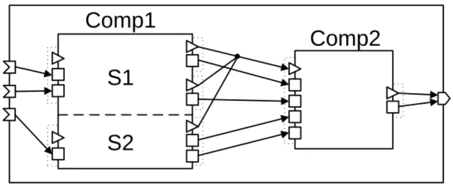
IP GFigure 2: ProSave components realizing a ProSys subsystem. The subsystem is realized by a composite ProSave component which is composed of two sub-components: Comp1 and Comp2. Comp1 has two services (S1, S2), whereas the functionality of Comp2 is provided by an unnamed service. Dotted rectangles denote port groups. Squares and triangles designate data, respectively trigger ports.
2.2
Technological background
2.2.1 Eclipse Platform
The Eclipse Platform [1][9][6] is a Java, open-source platform for building applications. It pro-vides developers with an extensible application framework and a set of components of various functionality able to build a rich client application. It has evolved from the Eclipse IDE, an ex-tensible IDE supporting multiple programming languages, to a generic platform for development of both GUI and non-GUI applications of various types.
The cornerstone of the platform is an extensible plugin architecture allowing for integration of various functionality contributed by plugins. A plugin is a unit enriching the Eclipse Platform with some functionality or providing other resources (e.g. help, images, etc.). Apart from its actual contents (source code, help files, etc.), it comprises a plugin manifest, which is a
CHAPTER 2. BACKGROUND 2.2. TECHNOLOGICAL BACKGROUND
specification of plugin run-time dependencies (plugins on whose functionality the plugin depends) and, in reverse, of classes exposed by the plugin to other plugins. In addition to run-time dependencies, the plugin manifest contains the definition of explicit points of extension of the plugin’s functionality that can be extended by other plugins. The plugin manifest also comprises the declarations of extending extension points defined by some plugins in the application (termed as defining an extension). This mechanism, called extension point mechanism, serves as the main means for achieving extensibility of the Eclipse Platform.
Plugins are not only design-time but also run-time entities managed by the Platform Run-time. The Platform Runtime is a small kernel forming the basis of each application built on the Eclipse Platform which manages plugins and their life cycles. Its role is to discover all plugins comprising an application, read their manifests and build a plugin registry, a database of all available plugins, extension points and their extensions accessible via API to the plugins. The runtime also executes the first plugin forming the basis of the application, and consequently activates all the plugins required for the given plugin to be loaded. The plugin activation is lazy meaning that plugin is not active unless one of its classes is demanded by another plugin.
The whole Eclipse Platform is built using this mechanism where plugins provide some func-tionality and points of extension to other plugins which in turn extend the former plugins and provide other functionality for yet another plugins, etc. The brief summary of the parts compris-ing the Eclipse Platform is given in Figure 3. The Eclipse Platform provides the functionality to build a full-fledged IDE (which is far more than a typical application requires). A basic subset of plugins sufficient to create a rich client application consisting mainly from the Platform Run-time, generic UI toolkits and several other features (see Figure 3) is called Rich Client Platform (RCP).
Figure 3: Eclipse Platform architecture [9]
Although the Platform provides a vast amount of functionality, there exist some parts that form a distinguishing characteristic of development in Eclipse. Since they were used heavily throughout the development of the attribute framework, their brief description is included. They are SWT, JFace and Workbench UI. All of them are concerned with the GUI of an application
CHAPTER 2. BACKGROUND 2.2. TECHNOLOGICAL BACKGROUND
focusing on different levels of its design.
The Standard Widget Toolkit (SWT) is a low-level GUI toolkit providing implementation
of common UI widgets. Its main characteristics is that the widgets are implemented using the native primitives offered by the underlying OS, as opposed to the Swing (standard Java GUI toolkit) approach which emulates all the widgets. JFace forms another level above the SWT (not necessarily hiding the SWT layer to a client). It is an OS window system independent UI framework providing high-level UI elements like dialogs, wizards, actions and viewers, which are adapters for some sophisticated SWT widgets (table, list, tree) supporting MVC-based1 design.
The Workbench UI is a framework forming typical UI paradigm of Eclipse-based applications
defining the behaviour and layout of larger UI elements comprising an application: application main window (called workbench), editors, viewers and perspectives. A main windows is com-posed of smaller UI parts of editors and viewers, whose layout configurations can be grouped and switched between by means of perspectives. Whereas editors serve as the main tool for modifi-cation of applimodifi-cation domain objects, viewers provide detailed information about the currently selected element in a workbench.
2.2.2 Progress IDE
The Progress IDE is an Eclipse RCP application developed within Progress. It is intended to provide engineering support for the whole development process envisioned by Progress. The output of the research conducted at Progress in the form of various tools, techniques and computations (e.g. analyses, verifications, synthesis) amending the process is to be integrated into the Progress IDE. The attribute framework elaborated in this thesis should be integrated with the Progress IDE as well.
2.2.3 Eclipse Modeling Framework
Eclipse Modeling Framework (EMF) [3][10] is a Java framework and a code-generation tool for creating parts of applications based on a model. By model it is meant some formal description of classes and their relations representing the entities from the application domain. EMF provides facilities for generating Java implementation of the model entities. The generated code can be further edited manually by a developer and it can also be regenerated when the model is changed having the ability to preserve manual code edits. At run-time, EMF offers several other utility features facilitating working with Java representation of the model entities: notifications about model entity changes, validation capabilities, persistence of the model entities (an XMI format by default). EMF also allows for an advanced reflective manipulation with model entities. Furthermore, one of the more advanced EMF features consists in defining models at run-time and being able to use the reflective manipulation for working with instances of those models (also called dynamic EMF).
Currently, input model representations can be in one the following formats: ECore XMI, annotated Java interfaces or an XML Schema. EMF converts these representations into its own modeling language called ECore. ECore is a simple modeling language able to represent classes and their features (primitive attributes or references to other classes). The above-mentioned reflective capability of working with model instances is realized by accessing object representation of ECore model instances.
Apart from the EMF core framework described above, EMF also consists of the EMF.Edit framework able to generate adapters to the model entities facilitating working with them in the Eclipse UI environment. Additionally, it is even capable of generating a simple GUI editor integrated with the Eclipse Platform for working with model entities.
1Model-view-controller, an architectural pattern distinguishing between model objects, their visual represen-tation and controlling their behaviour.
CHAPTER 2. BACKGROUND 2.2. TECHNOLOGICAL BACKGROUND
From a broader perspective, EMF can be seen as a simple application of the MDA (Model Driven Architecture) approach, which is based on defining a platform-independent model of an application, later on converted with the help of development tools to a platform-dependent model and finally to the code. However, EMF lacks the ambition to define some complex mod-els including the behaviour of the whole applications; instead, it focuses on a simple structural description, a kind of formalization of class diagrams, aiming to do rather a small job but thor-oughly so as to be usable in practice. Despite its simplicity, it still presents a new software de-velopment paradigm of modeling as another way of creating a software system by a (semi)formal specification used for generating the source code rather than programming manually.
In the text of the thesis, the terms of model and metamodel are used several times. Since they are closely connected with EMF, their explanation is included in this section. The model which is an input for the EMF code generation (the ECore model) is not a model of the real-world entities which are to be described. Instead, it is a specification of a description of these entities2, i.e. what are the names of the kinds of entities, their structure and relations between
each other. They are the instances of these descriptions which are actual models of the real-world entities. To terminologically distinguish between the two kinds of models, the former one is called a metamodel whereas as the latter one is denoted as a model.
2
More formally, it is the definition of the grammar of the language whose words represent the real-world entities.
Chapter 3
Problem Analysis
In this chapter the key requirements for properties and features of the ProCom attribute frame-work are specified. The chapter begins with a closer description of a component-based develop-ment process in the domain of embedded real-time systems focusing on the role of attributes. This description serves as a main source of the requirement specification in Section 3.2 and Section 3.4. Finally, functional requirements are concretized in the form of a set of use cases in the last part of the chapter.
3.1
Attributes in the development process envisioned by Progress
Regardless of a particular development process model, several main phases in the development of a software product can be identified [7]. These include
• requirement analysis and specification, • system and software design,
• implementation and unit testing, • system integration,
• system verification and validation (in relation to the requirements), • operation support and maintenance, and
• disposal.
Whereas in sequential process models (e.g. waterfall) these phases are carried out consecu-tively, in evolutionary models (e.g. iterative development, spiral model) they may be executed in parallel.
The CBD approach brings further amendments to the development process. There arises the need for completely new processes of selecting, adapting and testing components. More-over, it introduces the separation of the whole development process into two interdependent, parallel subprocesses of assembling a system from components and a component development, as mentioned in Section 2.1.2.
In order to specify the requirements imposed on the attribute framework of the ProCom component model, it is necessary to specifically focus on the development process as envisioned by Progress. Since the development process describes all involved activities, including those handling with attributes of modeled entities, it forms the ideal ground for requirements elicita-tion.
The key characteristics of the development process according to the vision of Progress, whose context is detailed in Section 2.1.3 and Section 2.1.4, are as follows [5]:
CHAPTER 3. PROBLEM ANALYSIS 3.2. GENERAL ATTRIBUTE. . .
• Pervasive usage of components (and subsystems on the system scale1) during the whole
development cycle from the early project phases of requirement specification and analysis throughout design and implementation up to the deployment of the system.
• Ability to move non-linearly, backwards and forwards in the development process both on the level of an individual component and on the level of the whole development process. To illustrate the necessity of the former transition (backwards, on the component level), consider the process of refining analyses and designs in later stages when some implemen-tation works have already begun. An example of the latter transition (forwards, on the system level) might be the specification of the characteristics of the deployment platform during the early phases of design.
• Different levels of abstraction of components in a system at the same time, the property inherent to the CBD, where the situation when a system consists of components that found themselves in different stages of development and thus of different levels of abstraction is the norm (e.g. a system consisting of a fully implemented component and a component whose development has not yet begun).
• Emphasis on analysis and verification during the whole process, dictated by the need of dependability and trustworthiness in the area of embedded real-time systems.
These characteristics have a major impact on the design of a component in ProCom. They require a component to be able to contain information associated to it during the different phases
of development and of different levels of abstraction.
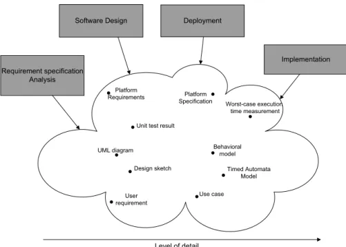
Having defined this key requirement for components in ProCom, the role of attributes in the whole process can be formulated. They are the attributes which are responsible for being able to contain all those different kinds of information associated to a component collected throughout the development process. The variety of included information is really immense (see Figure 4) as it ranges from requirement specifications, use cases and early sketches through results of various analyses (reliability predictions, functional compliance analysis, timing and resource usage analyses, etc.) up to detailed measurements of characteristics of the final version of a component.
Attributes are accessed by many actors taking part in the process, including humans (ana-lysts, designers, developers, people in charge of deployment, etc.) and other programs (analyses, synthesis), for which attributes can play a role of both an input and an output.
A process of such complexity would not be possible without a massive tool support. In respect of Progress, the Progress IDE becomes an essential part of the development process and the central point for all actors involved in it. All information relating to components, i.e. components’ attributes, should be accessed in a convenient way specific to the semantics and purpose of a particular piece of information by means of the IDE.
3.2
General attribute requirements
Taking into account the description of the Progress development process given in the previous section, we will now attempt to formulate the general requirements that should drive the whole analysis and design of the ProCom attribute framework.
As mentioned earlier, the information attached to components throughout the development process came from many sources. They are of a great variety of types and levels of abstraction. The first and evident requirement therefore is the attribute’s ability to support the containment
of a multitude of types of information.
1 For the sake of brevity, subsystems are not mentioned in this section, but the following statements about components can also be applied to subsystems.
CHAPTER 3. PROBLEM ANALYSIS 3.3. ACTORS WORKING WITH. . . Level of detail Deployment Implementation Software Design Requirement specification Analysis Use case User requirement Timed Automata Model Behavioral model Unit test result
Platform Specification Design sketch UML diagram Worst-case execution time measurement Platform Requirements
Figure 4: Various information included in component’s attributes
In the current state of the Progress project, it is not possible to obtain a definite list of all potential attributes that could be assigned to a component — the processes are not yet fully defined, many analyses and the synthesis are in a phase of sketches and early designs. But even if everything was already fully specified, there is always the possibility (approaching to certainty) of improving or adding some new step to the whole process. Hence, there arises the need for adding new information to a component, or in other words, attributes are required to be extensible. In fact, the importance of this requirement gave the name to the whole attribute framework.
However, what has just been pointed out as the need for extensibility might be also realised, due to the vagueness of the requirement specification, by creating a fixed pool of attribute data types and letting the users of the framework add new attributes of some of the known types from the pool. Although this is also intended functionality, it obviously does not suffice to meet the needs of the development process. It is necessary to be able to introduce completely new kinds of information, instances of new data types. Therefore, another requirement imposed on the attribute framework refining the previous one is type extensibility.
3.3
Actors working with attributes
Before continuing further with specifying more concrete requirements, the main actors involved in working with the attribute framework will be identified as it will help to structure the following discussion. Again, the development process description from Section 3.1 is the main basis for the following enumeration.
The first group of users of attributes are people who access components’ attributes through-out the whole development cycle: analysts, designers, system architects, component developers, etc. Their common characteristic is that they use facilities offered by the Progress IDE to work with the data associated with components using attributes, and these data are their primary concern. These users will be referred as IDE users.
CHAPTER 3. PROBLEM ANALYSIS 3.4. REQUIREMENT SPECIFICATION
inputs and outputs of various computations over the model, e.g. various analyses and simula-tions. The second group of attribute framework users consists of developers programming those computations. They are using a completely different interface than IDE users to interact with the framework: they communicate through the framework’s programmatic interface. Since the usage of this interface does not have to be necessarily constrained only to computations over model, but it might involve arbitrary invocation by any program module of the IDE, this group of users will be denoted as IDE module developers.
Although the previous actors interact with the attribute framework in completely different ways, both of these groups have something in common: they just use the existing attributes and attribute types and they do not extend them in any way. And since the key requirement for attributes is their (type) extensibility, another actor who is responsible for adding a new attribute or a new attribute type is needed. Typically, these actions will be carried out by a developer of the Progress IDE or an architect of the ProCom model, employing another part of the attribute framework which enables to plug in modules extending the capabilities of the framework. In the context of this thesis, such users will be called attribute contributors.
Not only do these three groups of users specify basic actors, but they also define three different areas of the attribute framework itself. This natural division will be used many times in the following text.
3.4
Requirement specification
Having realized the main actors involved in working with the attribute framework, the discussion about the requirements imposed on the attribute framework can now be structured according to these actors. First, the requirements for attributes common for both IDE users and IDE module developers2 are specified. Afterwards, we continue by enumerating requirements specific to the
particular groups of users.
3.4.1 Common attribute requirements
So far, only components were considered as entities to which attributes can be attached. How-ever, during the process it might be necessary to associate some information that is related to some entity inside a component (e.g. a port or a service) as well as to some object encapsulating a component (e.g. subsystem). Accordingly, attributes are required to be attachable to many
types of ProCom entities both in the ProSave and ProSys layers.
Immediately, there follows another request refining the previous one. If attributes are allowed to be associated with many types of entities, it is almost automatically expected that there exists the possibility of defining to which kinds of entities can a particular piece of information
be attached and to which it is not applicable.
Let us now focus more on the pieces of information associated with the ProCom entities. The first general requirement for the attribute framework was concerned with the support for a variety of kinds of information that can be attached to the model entities. Ranging from simple value types (e.g. integers, strings) to use cases and sophisticated behavioural models represented by e.g. timed automata, they truly represent a wide scale of data types. However, there might be the need for some parts of information to be common to several or all of the supported data types. It is not sufficient to have opaque data whose semantics is hidden inside the inner structure of the opaque pieces of information. There should be some data members common to all attribute data types (e.g. version or comment) known to the framework, helping the framework to classify associated information in a uniform way without actually peeking inside the main data chunk (e.g. a use case or a timed automaton). This requirement can be formulated as demand for the structure of the pieces of information known to the framework.
2
Common attribute requirements describe the structure of attributes, which is of minor interest to attribute contributors.
CHAPTER 3. PROBLEM ANALYSIS 3.4. REQUIREMENT SPECIFICATION
One of the characteristics of the ProCom development process mentioned in Section 3.1 was the ‘ability to move backwards to earlier phases in the development process of an individual component’, which resulted in the design of a component where it contains information of different levels of abstraction associated to it during the different stages of the development.
Practically, this implies there can be several data values of the same characteristic on different levels of abstraction associated with a component. As an example, the attribute of the worst-case execution time of a service of a component can be taken: In the early phases of development there was made an estimate by an expert. Later, when behavioural models were elaborated, the same characteristic was computed in a simulation using the models. And finally, in the testing phase some precise worst-case execution time measurement was performed. Naturally, all these values need to be associated with the component (or rather with the service). This example illustrates one important implication of the above-mentioned ProCom feature. There is the need for the attribute framework to be able to contain several pieces of information related to the
same characteristic of a component.
3.4.2 Terminology clarification
Before proceeding to the requirements specific to particular groups of users of the attribute framework, the usage of the terminology should be clarified and made consistent.
Up to now, the terms ‘piece of information associated with a model entity’ and ‘attribute’ were used intuitively and rather in an interchangeable way. However, the last requirement for the attribute framework, ‘to contain several pieces of information related to the same characteristic of a component’, forces us to distinguish two notions. The first is the notion of a characteristic of an entity, a property or a feature of an entity with precisely defined semantics, which will be referred as an attribute in the remaining text of this document. The second one is a particular piece of information, analogous to an instance of a data type (from the domain of programming languages), associated with an attribute, that represents or measures the quality of an attribute or, simply said, attribute value.
Using this terminology, the requirements stated above could be rephrased as follows: • An attribute should be attachable to many types of ProCom entities both in the ProSave
and ProSys layers.
• It should be possible to define to which types of entities a particular attribute can be attached and to which it is not applicable.
• An attribute value should be structured in a way known to the framework. • An attribute should be able to contain several attribute values.
3.4.3 IDE users requirements
The following set of requirements reflects the needs of the Progress IDE users. The first one is
to integrate the attribute framework to the IDEmaking the whole interaction possible. However,
such specification needs to be refined by taking a closer look at the details of the development process.
Since actors start working with attributes as soon as they start using components, and the two activities are overlapping during the whole development process, there should be smooth
in-tegration between the ProCom model editor, which is responsible for creating and linking various
ProCom entities, and the attribute framework. By the smooth integration it is meant that the framework should be aware of some important events (e.g. selection of a ProCom model entity) happening in the ProCom editor and it should then react to them accordingly.
Another important aspect of the framework’s integration into the IDE should be its
CHAPTER 3. PROBLEM ANALYSIS 3.4. REQUIREMENT SPECIFICATION
employing the well-known paradigm for working with properties of edited objects (e.g. text pro-cessors, vector graphics editors, etc.). Reusing some typical procedures might help to decrease learning time and increase user comfort.
Let us focus now more on the functional requirements imposed by IDE users. An IDE user, regardless of his role in the development, uses the attribute framework in order to access data associated with model entities, or more precisely, an IDE user accesses attribute values. They are the data stored using attributes that the user is primarily interested in as they become inputs or results of his or her work on the model. Consequently, the framework is required to support
basic operations with an attribute value: adding a value to an entity, removing a value from an
entity, viewing and editing a value. All of these operations are described closer in the section of use cases (Section 3.5). However, the last two represent more complex operations that yield another requirements.
The viewing of an attribute value is an action in which the framework provides an IDE user with a visual representation of the data stored in the attribute value. The visual representation
should be chosen in accordance with the data type and the semantics of the attributefacilitating
the user’s work to a maximum extent. The editing of an attribute value is similar to the viewing in the respect that it should also be attribute-specific. But whereas the primary goal of viewing was to facilitate understanding of a value by proper visualisation, editing aims at providing means
for comfortable and effective modification of a value. Thus, the above-mentioned intentions
typically lead to different appearances of the GUI realizing them, which is the reason why viewing and editing are separated even though viewing can be generally perceived as a special case of editing with no modification performed.
As there exist plenty of possible kinds of information which could be eventually attached to model entities, it is likely that there will be a great number of attributes associated with entities. Therefore, several requirements whose motivation is to make it easier for a user to deal with many attributes are needed.
Attribute values should be manipulated in a uniform way independently on their attribute type. Although there will be some attribute-specific aspects of behaviour (e.g. when viewing or editing values), the general manipulation procedures should be the same making it easier to work with types not yet known to the IDE user.
Another approach towards dealing with numerous attributes lies in localizing and centralizing
the control of attributes in a GUI element or a group of related GUI elements. Attributes
should be aggregated in one place, and a user should not be forced to search for a GUI element responsible for controlling a particular attribute value he or she wants to access.
Immediately, there follows an opposite requirement to the aggregation but facilitating work-ing with many attributes as well. Attributes should be divided into some semantically similar
sets, which would help a user in finding an attribute of his interest. For example, attributes
might be divided into several categories (e.g. reliability, performance, deployment, resource consumption) according to what characteristic they measure.
Finally, in order to be well understood by users, attributes should be supplied with
documen-tation accessible from the GUI.
3.4.4 Module developers requirements
IDE module developers use the attribute framework for working with attribute values similarly to IDE users. However, in contrast to IDE users, they access attribute values programmatically from the Progress IDE modules they create. For this reason, they require the framework to
have a public API3 allowing them to manipulate attribute values. Because the Progress IDE
as well as its modules are intended to be implemented in Java, the API in this context means a public set of Java class(es) and/or interface(s).
CHAPTER 3. PROBLEM ANALYSIS 3.4. REQUIREMENT SPECIFICATION
In order to specify what features the framework’s API must provide, the needs of IDE users can be taken as an inspiration. The API has to allow developers to add, remove and access
an attribute value of a particular model entity. However similar these requirements are, it is
worth noting the difference between the meaning of the notion of an attribute value for IDE users and module developers. Whereas the former group of users perceive an attribute value only indirectly by means of the facilities that the framework provides them to view and edit the value focusing then only on its visual representation, the latter group of users come in direct contact with the programmatic representation of an attribute value because it forms an output or input of the computations they perform.
The representation should be flexible enough to be able to contain possibly highly structured
or complex data that might be stored in attributes, but at the same time it should also allow the developers to access its structured contents in a comfortable way.
3.4.5 Attribute contributors requirements
As mentioned before, attribute contributors are concerned with adding new attributes and at-tribute types to the framework and thus form the only group of users that is able to extend the framework capabilities. They do not use neither the GUI nor the API for module developers (the client API ) to perform their job. Instead, they require another interface to be provided by
the framework. It is also a specific kind of an API but with a different role. Whereas the client
API was intended to provide its users with the attribute framework’s functionality, this API, to the contrary, allows its clients to add new functionality to the framework. There exists a term for such a kind of API4 - Service Provider Interface (SPI), which will denote the part of the
framework used by attribute contributors.
In order to express which features the attribute contributors need the SPI to provide, it is necessary to realize what it means to add a new attribute or a new attribute type. A more general case of adding an attribute of a completely new type is considered. First, a contributor has to
specify an attribute value type, a description of the data structure of an attribute value, which
will later be associated with the attribute being added and whose realization will be exposed to module developers. Next, they need to define the attribute itself. Taking into account the requirements imposed earlier in the text (Section 3.4.1), an attribute definition consists of the following parts:
• a specification of an attribute value type, a type of values associated with the attribute being defined, realized by a reference to the type created in the first step of the contribution, • providing the framework with the facilities for viewing and editing values of this attribute
in the GUI of the Progress IDE,
• a specification of type(s) of the ProCom model entity(ies) to which attribute can be at-tached,
• providing the framework with any other functionality that might be required to manipulate the values of a given attribute.
Compared to the requirements for the client API, the SPI might not be represented only by Java classes and interfaces. Here, we adhere to the broader semantics of an API (and consequently SPI) as a set of all means used in interaction between the attribute framework and its contributors.
4
CHAPTER 3. PROBLEM ANALYSIS 3.5. USE CASES
3.5
Use cases
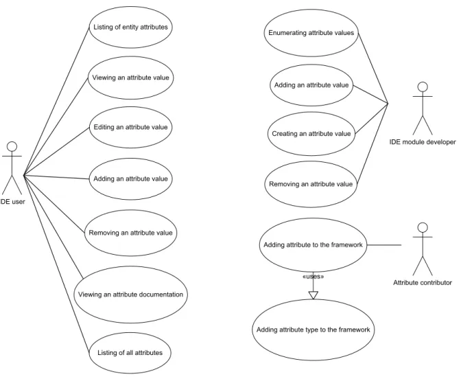
In this section, the functional requirements (see Figure 5) for the framework imposed by the actors defined in Section 3.3 are summarized in the form of use cases and provided with brief descriptions.
IDE user
Listing of entity attributes
Viewing an attribute value
Editing an attribute value
Adding an attribute value
Removing an attribute value
Viewing an attribute documentation
IDE module developer Enumerating attribute values
Adding an attribute value
Removing an attribute value
Attribute contributor Adding attribute to the framework
Adding attribute type to the framework «uses»
Listing of all attributes
Creating an attribute value
Figure 5: Actors in the attribute framework and their associated use cases
3.5.1 Use cases associated with an IDE user
Since in the following descriptions we need to refer to the GUI component of the Progress IDE responsible for working with attributes, we will denote it as Attribute View. However, it should be noted that it might not fully correspond to the final implementation, where the Attribute View may be represented differently, e.g. by several GUI elements.
Listing of entity attributes
An IDE user displays in the AttributeView all the attributes and their values attached to a ProCom entity selected in the ProCom model editor.
Viewing an attribute value
An IDE user views the value of an attribute selected in the Attribute View. Viewing of a value of some complex type might require opening a specialized viewer.
Editing an attribute value
CHAPTER 3. PROBLEM ANALYSIS 3.5. USE CASES
value of some complex type might require opening a specialized editor. Adding an attribute value
An IDE user adds a new attribute value to an attribute selected in the Attribute View. Removing an attribute value
An IDE user removes an attribute value selected in the Attribute View. Viewing an attribute documentation
An IDE user displays the documentation describing the usage of an attribute selected in the Attribute View.
Listing of all attributes
An IDE user displays the list of all the attributes contributed to the attribute framework, from which the attribute documentation will be accessible.
3.5.2 Use cases associated with an IDE module developer
All of the use cases contained in this section are performed programmatically using the frame-work’s client API, and each corresponds to a Java interface or a class method call, which is the reason why the term ‘caller’ is used for an actor who carries out these use cases. Furthermore, it is assumed that a caller has programmatic access to entities of a ProCom model.
Enumerating attribute values
A caller retrieves a set of attribute values associated with an attribute of a model entity. Creating an attribute value
A caller creates a new attribute value of an attribute. Adding an attribute value
A caller adds an attribute value to the values of an attribute of a model entity. Removing an attribute value
A caller removes an attribute value from the values of an attribute of a model entity.
3.5.3 Use cases associated with an attribute contributor
Currently, there are two use cases associated with the actor of an attribute contributor: Adding attribute to the framework
An attribute contributor appropriately specifies all the items comprising the definition of an attribute (in the case of adding an attribute of a new type, the type is included, which is realized by the next use-case).
Adding attribute type to the framework
An attribute contributor appropriately specifies the definition of a new attribute type. Contrary to the use cases mentioned previously, which were simple actions from the actor’s point of view, the use cases associated with an attribute contributor are much more complex. They are refined in further chapters of the thesis. Requirements relating to them can be found in Section 3.4.5.
Here, let us explain why there are two separate use cases. It does not mean that these would have to be necessarily separate actions, but it should stress the fact that adding an attribute whose type is already known to the framework should be much more straightforward process than the case when even the attribute type specification is contributed.
Chapter 4
Solution Design
This chapter contains the important design decisions made during the development of the at-tribute framework. They are presented together with their explanation and evaluation of con-sidered alternatives.
4.1
Integration with the ProCom metamodel
ProCom is formally defined in the form of a metamodel1 describing entities, whose instances
comprise the ProCom models of developed software systems, and relations between these enti-ties. The metamodel is basically a UML class diagram where classes correspond to the ProCom entities and relations between them are modeled using the relationships of aggregation, com-position, and association. The classical approach to modeling characteristics (or properties) of entities in UML employs class attributes2. Whereas early versions of the ProCom metamodel
used this approach, it is insufficient in the context of this thesis.
The main reason lies in the anticipated high frequency of adding new attributes to ProCom during the initial phase of the Progress evolution. As more and more parts of the development process (e.g. deployment to virtual and physical nodes, different kinds of analyses, synthesis, etc.) will get gradually specified in more detail, they will need to associate more kinds of information with components or other ProCom entities, i.e. they will need to add new attributes. If the ProCom attributes were modeled using the class attributes in the metamodel, every addition of a new ProCom attribute would mean extending the respective model entity class and consequently an extension of the whole ProCom metamodel. Changing the metamodel is an expensive operation because the metamodel does not only serve as a formalization of the ProCom but also as a source for a code generation process that produces code representation of the model (using EMF). There are even more code artifacts generated from the EMF model, including the parts of model editor. And all these would be influenced by the metamodel extension.
Another reason relates to the maintainability of the metamodel. It is expected that there will be tens or even hundreds of attributes, which would clutter the metamodel. Although attributes play an important role in ProCom, there exist more defining characteristics of the component model (e.g. components, services, ports and their relationships). From this perspec-tive, attributes are of a secondary importance and their presence in the metamodel would rather aggravate future ProCom evolution.
As a result, one of the tasks of the attribute framework consists in minimizing the effects of adding a new attribute on the ProCom metamodel. Still, attributes are the part of a component model and thus they should be reflected in its formalization, i.e. metamodel. The chosen solution detailed in this chapter is based on inclusion of the notion of an attribute and its refinement
1
The difference between model and metamodel is explained in Section 2.2.3. 2
As opposed to the rest of the text where ‘attributes’ refer to the ProCom attributes, here we have the semantics of the term as used in object-oriented programming in mind.
CHAPTER 4. SOLUTION DESIGN 4.2. ATTRIBUTE STRUCTURE
in the metamodel. However, particular characteristics of model entities, instances of attributes, are kept separately from the metamodel and are managed by the attribute framework.
After a closer examination of the role of attributes in the ProCom metamodel, it has been concluded that attributes, as a general means for associating various information with different ProCom entities, are not dependent on the remaining part of the metamodel.3
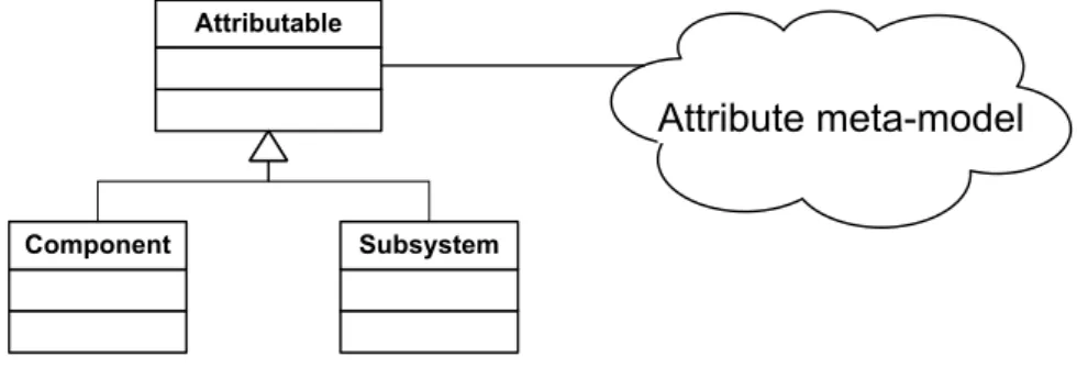
Conversely, certain parts of the ProCom metamodel must depend on attributes since some of its entities need to have attributes. To minimize the dependency between these two parts of the metamodel, an attributable, an entity capable of having attributes, has been introduced. The Attributable class is the only entity of the part of the metamodel related to attributes (attribute metamodel) which is directly used by the rest of the metamodel, and it therefore plays the role of an interface of the attribute metamodel. This design also makes it possible to completely hide the implementation details of the attribute metamodel and provide the facade in the form of methods of Attributable. ProCom entities having attributes are then modeled by subclassing Attributable (see Figure 6).
Attributable
Component Subsystem
Attribute meta-model
Figure 6: Attributable and its role in the attribute metamodel
An alternative to the realised solution is to use the relationship of composition. An entity with attributes could be modeled as a class that is composed of attributes, i.e. it has a com-position relationship with a class representing an attribute. This design exhibits the following drawbacks:
• ProCom entities refer directly to the representation of an attribute, revealing the internals of the attribute metamodel.
• The attribute framework cannot determine whether an entity of the model has attributes or not from the class of the entity (as opposed to test whether an entity is a subclass of Attr-ibutable). This implies that there would have to be a part of the framework enumerating ProCom entities with attributes, which would make the framework dependent on ProCom and consequently less general.
4.2
Attribute structure
In this section the core classes of the attribute framework representing the notions of attribute and attribute value are elaborated. They can be viewed as more detailed and formalized versions of these notions, which were defined during the problem analysis, and they influence many aspects of the framework’s design.
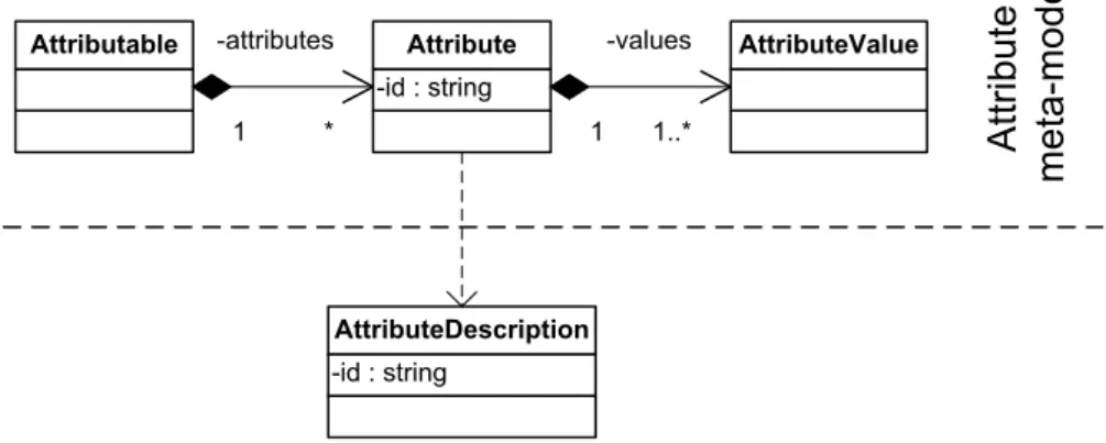
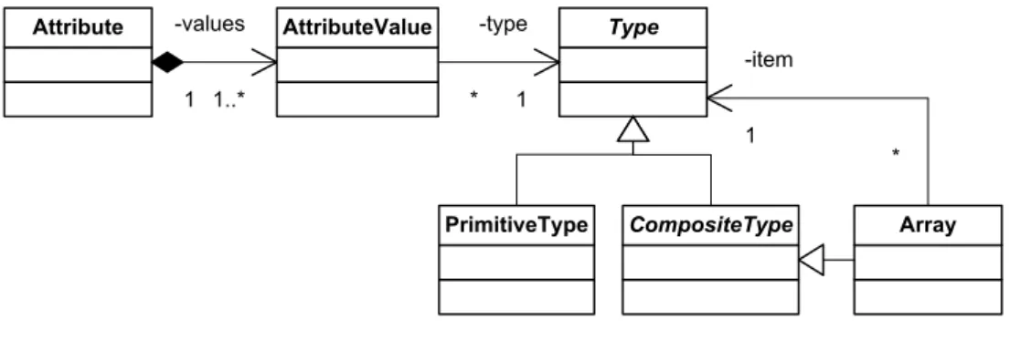
Three main entities forming an attribute and its associated values have been identified. They are common to all kinds of attributes regardless of the type of their values. These are an attribute, an attribute value and an attribute description. Each of these entities is directly represented by a class of the same name, as depicted in Figure 7.
3
![Figure 1: ProSys subsystems communicating using a message channel [14]](https://thumb-eu.123doks.com/thumbv2/5dokorg/4884077.133702/12.892.241.693.920.1026/figure-prosys-subsystems-communicating-using-a-message-channel.webp)
![Figure 3: Eclipse Platform architecture [9]](https://thumb-eu.123doks.com/thumbv2/5dokorg/4884077.133702/14.892.137.794.595.1055/figure-eclipse-platform-architecture.webp)