http://www.diva-portal.org
This is the published version of a paper presented at IECON 2013 - 39th Annual Conference of the
IEEE Industrial Electronics Society, 10 Nov - 13 Nov 2013, Vienna.
Citation for the original published paper:
Yu, K., Gidlund, M., Åkerberg, J., Björkman, M. (2013)
Low Jitter Scheduling for Industrial Wireless Sensor and Actuator Networks.
In: 39TH ANNUAL CONFERENCE OF THE IEEE INDUSTRIAL ELECTRONICS SOCIETY
(IECON 2013): 39th Annual Conference of the IEEE Industrial Electronics Society (pp.
5594-5599).
IEEE Industrial Electronics Society
http://dx.doi.org/10.1109/IECON.2013.6700050
N.B. When citing this work, cite the original published paper.
Permanent link to this version:
Low Jitter Scheduling for Industrial Wireless Sensor
and Actuator Networks
Kan Yu
∗, Mikael Gidlund
†, Johan ˚
Akerberg
†and Mats Bj¨orkman
∗ ∗M¨alardalen University, Sweden†ABB AB, Corporate Research, Sweden
Abstract—Applying Industrial Wireless Sensor and Actuator Networks (IWSANs) in the industrial automation is a growing trend due to flexibility, mobility and low cost. According to the current standards, such as WirelessHART and ISA100.11a, multi-channel TDMA transmission is included for reliable and deter-ministic communication. In this paper, we clarify the dependence of TDMA scheduling for sensors and actuators and point out the low correlation between the scheduling delay and the overall quality of control, and focus on reducing jitter in scheduling for improving quality of control and system stability. We propose a scheduling algorithm, aiming for lowing jitter and compare it with two traditional real-time scheduling schemes. Our simu-lation results exhibit significantly lower jitters by applying our scheduling policy than those two traditional scheduling schemes. Index Terms—Industrial Wireless Sensor Network, scheduling, TDMA, real-time, jitter, centralized control, PLC
I. INTRODUCTION
Nowadays, wireless communication systems, especially in-dustrial wireless sensor and actuator networks (IWSANs) have been exhibiting their attractive advantages over traditional wired counterpart for industrial automation, such as flexibility, scalability and low cost. Due to stringent requirements of reliability and real-time performance, three major industrial communication standards have been produced, namely Wire-lessHART, ISA100.11a and WIA-PA. All these standards apply Time division multiple access (TDMA) mechanism on the MAC layer to provide deterministic communication. Thus, the TDMA scheduler of the system shall allocate sufficient timeslots for all sensors, actuators and gateway in a proper way. However, all these standards do not specify use of any particular scheduling algorithm. Therefore, users should define their own scheduling scheme according to their requirements. Currently, extensive research efforts have been taken to investigate real-time scheduling [1]–[7]. Most of the research works focus on schedulability. There is no doubt that schedu-lability is important, but there still exist other important requirements of scheduling in IWSANs. For a control system, IWSANs participate as one part of the whole control loop. As we know that delay and jitter are two factors which can degrade the quality of control. Therefore, some previous re-search works [4] focus one reducing the latency in scheduling. It might be effective in other scenarios, but in IWSANs, where end-to-end communication can hardly be synchronized due to different communication protocols and different settings of the Programmable Logic Controllers (PLC), reducing latency in scheduling has quite limited contribution on improving the
overall quality of control. This is one of the old concerns we will clarify in this paper. Jitter, as another factor of control quality degradation, shall also be paid much attention, since high jitter severely degrades the quality of control and even results in system instability. However, until now no research work can be found on reducing jitters in scheduling for IWSANs.
In this paper, we first clarify two previous concerns about scheduling in IWSANs. These two concerns are the depen-dence of scheduling for sensors and actuators in IWSANs, and the correlation between the scheduling delay and overall quality of control. Then we provide deep insight into the origin of jitters caused by timeslot allocation. Afterward, we propose our low jitter scheduling scheme. According to our scheduling algorithm, we first allocate timeslots for starting and ending jobs for each tasks and schedule the rest of the jobs based on their priorities. Finally, we compare our scheduling policy with other two well-known real-time scheduling policies to evaluate the jitter performance. Our simulation results exhibit a significantly lower jitter by applying our scheduling policy than those two traditional scheduling schemes.
In the sequel, in Section II we classify the old concerns and bring a new concern of scheduling in IWSANs. Section III presents the proposed low jitter scheduling algorithm. Simulation results are presented and discussed in Section IV. Conclusions are drawn and summarized in Section V.
II. PRELIMINARY
In this section, we start with the introduction of IWSAN structure and existing standards, then we present the require-ments of scheduling in IWSANs. Finally, we introduce the controlled flooding-based routing scheme as the basis of our scheduling scheme.
A. Industrial Wireless Sensor and Actuator Network and Ex-isting Standards
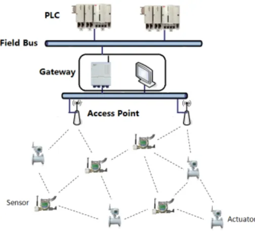
A typical IWSAN is built of several basic elements, such as spatially distributed sensors and actuators, one or more access points, one gateway and one network manager. A general structure of IWSNs is shown in Figure 1. Sometimes, the access point, gateway and network manager are built as one entirety, which is connected to PLCs through the field bus.
Each element mentioned above has its own periodic behav-ior. A sensor periodically measures the status. Measurement results are periodically uploaded to the gateway. The field bus
Fig. 1. Example of an IWSN structure
periodically forwards measurement values to the PLC, and then commands are executed in PLC in a periodic manner. In a best case, everything in the network is synchronized, since asynchronization results in extra latency. Full synchro-nization might be simple if only one communication protocol for control systeme is involved. However, practically, several different communication protocols may be applied, such as HART, Modbus and profibus. Thus, protocols should be con-verted to each other. After each communication protocol being converted, it is extremely difficult to keep all communication synchronized. Moreover, tasks may be executed in different PLCs. If different communication protocols and signal media are used by different PLCs, it is also extremely hard to make the whole control system fully synchronized. Therefore, practically we can see communication in a control system to be asynchronized.
WirelessHart [8], ISA100.11a [9] and WIA-PA [10], as three major standards, have been or going to be used in industrial automation. TDMA transmission is applied on the MAC layer in all these standards to be avoid of unpredictable collision. Since different timeslot allocation methods result in different network behaviors, in order to provide reliable and deterministic transmission, TDMA scheduling schemes applied on the MAC layer is extremely important.
B. IWSANs Scheduling Requirements
Generally, scheduling schemes can be classified as two primary categories: centralized scheduling and decentralized scheduling. Typically, the topologies of IWSANs are cen-tralized, which means that the network manager takes the full responsibility of the whole network behavior. Thus, in this work we only focus on centralized scheduling schemes. Before scheduling the network, the network manager needs to collect sufficient information about the current network topology. Then sufficient timeslots shall be allocated for the whole network. During the scheduling execution and decision distribution period, the network manager assumes that the en-vironment stays static and does not change in time. Therefore, an off-line scheduling scheme is more suitable for this case.
Previously, there exists two old concerns for scheduling in IWSANs. The first one is the dependence of the timeslot allocation for sensors and actuators [5]. From the control loop point of view, a sensor needs to be scheduled first to send the measurement value to the controller, then after execution, the command is transmitted to the actuator for reaction. Therefore, it seems that sensors must be scheduled before actuators. It is the truth, merely when the whole control system is fully synchronized. As we emphasized in the previous subsection, due to the existence of multiple PLCs with different com-munication protocols, practically we shall consider the whole control system as asynchronized. Therefore, during scheduling we are able to consider that timeslot allocations for sensors and actuators are totally independent with each other.
Another previous concern for scheduling is about the scheduling delay and the quality of control. For a TDMA scheduling, we assume that a packet is scheduled to be sent at slot S and arrives at slot R, then the delay can be calculated as R − S + 1. In general, decreasing the end-to-end latency from the sensor to the actuator can improve the quality of control, since the effect of long latency in a control system resembles the effect of lowering the sampling frequency. However, due to the asynchronization problem mentioned above, only reducing the latency of scheduling will have very limited effect on decreasing the overall latency. The reason is that packets may come just after the slot S. Then the packets shall wait for the next S in the next cycle. Then the actual delay in scheduling is not the same as the desired one. Research efforts taken on reducing the scheduling delays may have limited improvement of the quality of control in existing IWSANs.
After clarifying those two previous concerns, in this paper, we bring a new concern to the scheduling for IWSANs. Com-pared with low latency in scheduling for IWSANs, predictable delay and deterministic behavior in scheduling is much more important. As we assume a packet should be sent by the source at slot S and arrive at the destination at slot R, if after the scheduling decision, the packet actually is sent at slot S0 and arrives at slot R0, then we define |S0− S| and |R0− R| as
the jitters caused by the scheduling scheme. Since these jitters may cause control performance degradation, we should aim for low jitter; in other word, try to reduce |S0− S| and |R0− R|,
rather than reducing scheduling delay. However, until now no research work can be found on trying to reduce the jitters in scheduling for IWSANs. Therefore, our work mainly focuses on providing low jitter scheduling for IWSANs.
C. Controlled Flooding-based Routing Scheme
Before determining the scheduling algorithm, a routing protocol should be defined. Previous scheduling works in IWSANs are all based on graph routing protocol [2]–[4]. Different from before, for better reliability and real-time performance, our scheduling scheme is based on a controlled flooding-based routing protocol [11]. The main differences for scheduling between graph routing and controlled flooding-based routing are: 1) multicast transmission is considered, instead of unicast; 2) retransmissions are not required to be
scheduled; 3) packet forwarding in flooding-based routing is based on related node lists, rather than graph ID. Each node maintains a related node list. If the source address of a packet is included in the list, this packet is allowed to be forwarded. To give the topology information to the gateway, all nodes send their parent node IDs and hop numbers to the gateway, so the gateway knows the network connectivity information for further scheduling decision. More details refer to [11].
III. LOWJITTERSCHEDULINGSCHEMEFORIWSANS In this section, after the introduction of the notations throughout the paper and task model, our proposed scheduling scheme aiming for low jitter is described in detail.
A. Notations and Task Model
We assume that an IWSAN as a set N consists of n nodes, N = {N1, N2, ...Nn}, including sensors and actuators. Since
each node periodically sends current status to the gateway or receives commands from the gateway, we consider a set τ composed by n periodic tasks.
A task τk consists of a sequence of jobs jki. Because in a
multihop IWSAN due to the flooding mechanism one packet should be re-flooded several times to arrive at the destination, a job ji
k represents the i-th re-flooded behavior in the network
for the k-th node. Every task τk = (Ck, Dk, Tk) ∈ τ is
characterized by a required timeslots Ck, a relative deadline
Dk and a period interarrival time Tk.
According to the standards, maximumly 16 different chan-nels can be used. Thus, we assume that m chanchan-nels are available for our scheduling. Hence, a job jki can be scheduled in any of these channels.
Besides timeslots, each task τk also requires nodes as shard
resources for sending and receiving packets. However, one node can only transmit one packet or receive one packet at one timeslot. If one node is occupied by one task, other tasks intending to use the same node will be suspended.
B. Scheduling Scheme Aiming for Low Jitter
Before scheduling, tasks with a sequence of consecutive jobs shall be determined. As we described above, each task corresponds to a node in the network. The number of jobs in each task is determined by the number of involved inter-mediate nodes plus the source node. Thus, each job in this task corresponds to an intermediate node. To construct all tasks, the network manager shall be aware of the network topology and know all involved intermediate nodes. Consider to construct a task τk corresponding to a sensor Nk. For this
node Nk, all its parent nodes are expressed as a set Pk, its
hop number is written as Hk. Then the task τk construction
approach by the network manager is summarized in Algorithm 1. The construction of the task for an actuator follows the same approach and is omitted here. In the algorithm, B is the buffer set to record all previous parent nodes in the task. If a node Ni is an intermediate node of the node Nk, then a
corresponding job jl
k will be created and added into the task
τk. For uplink transmission, if an intermediate node is more
hops away from the gateway, its corresponding job should be added in the task earlier than those with fewer hops. To the contrary, for downlink transmission, jobs with fewer hops will be added first. Finally, all tasks for all communication in the network can be created.
Algorithm 1 Task Construction Procedure
1: Sort all nodes according to their hop numbers in descend-ing order: H1> H2> ... > Hn, except for Nk
2: B = Pk, l = 0
3: for all Hi from H1 to Hn, except Hk do
4: if Hi≤ Hk then 5: if Ni∈ B then 6: l = l + 1 7: B = Pi∪ B 8: add jl k to the task τk 9: end if 10: end if 11: end for
According to the standards, all communications are orga-nized into superframes to group a sequence of consecutive timeslots. The superframe length of a node Nk is determined
by the refresh rate of this node. Thus, we let Tk of this task τk,
as the corresponding task of the node Nk, equal the superframe
length, represented as the number of required timeslots in one period. In order to schedule timeslots efficiently, we consider another concept, called hyperframe. The length of the hyperframe Lhyperis defined as as the least common multiple
of all superframe length, which is represented as lcm(Tk), k =
1, 2, ..., n of the periods of all tasks. Thus, one hyperframe may contains several superframes. Then the scheduling decision is based on hyperframe, instead of superframe.
For lower scheduling jitter, we give deep insight into the origin of the jitter. There are two main reasons of the scheduling jitter. First reason is the multiple arrivals of each packet. For multipath routing protocol, each packet arrives at the destination via several different paths. Although only the first arrival packet is considered, if the first transmission fails and the latency from different arrivals differ a lot, jitter will be introduced. Therefore, when scheduling timeslots, we shall make the difference of different arrivals time as little as possible. Secondly, for a multihop network, the drift of the starting slot position and ending slot position in a superframe also brings jitter. For instance, consider one packet is sent at slot S1and arrives at slot R1in the first superframe, and sent
at slot S2and arrives at slot R2in the second superframe. Even
if the transmission latency R1− S1+ 1 in the first superframe
equals R2− S2+ 1 in the second superframe, from the control
system point of view, incoming packets arrive at an unstable pace, since the arriving time varies. Thus, no transmission time jitter does not mean no jitter to the control system. The larger values of |R2− R1| and |S2− S1| will lead to more jitter to
the control system.
To make the scheduling scheme with lower jitter, we shall try to reduce two types of jitters mentioned above. Thus, our
Algorithm 2 Low Jitter Scheduling Scheme
1: Sort all tasks according to refresh interval in ascending order: T1< T2< ... < Tn.
2: for all Ti from T1 to Tn do
3: Schedule the starting job j1
i from the starting position
in each superframe 4: if Scheduling fails then
5: Move to the next timeslot and repeat Line 3 6: end if
7: end for
8: for all Ti from T1 to Tn do
9: Schedule all ending jobs ji(end)from the ending position in each superframe
10: if Scheduling fails then
11: Move to the previous timeslot and repeat Line 9 12: end if
13: end for 14: s = 0
15: while τ 6= ∅ do 16: for all τk ∈ τ do
17: Compute the priority λk based on s
18: end for 19: ch = 0
20: Sort priorities in descending order : λ1> λ2> ... > λn
21: for all λi from λ1 to λn do
22: Schedule the job ji at the timeslot s
23: if Scheduling succeeds then 24: ch = ch + 1 25: end if 26: if ch ≥ m then 27: s = s + 1 28: break; 29: end if 30: end for 31: s = s + 1 32: if s ≥ Lhyper then 33: Return FAIL; 34: end if
35: if all jobs jk ∈ τk are scheduled then
36: τ = τ − τk
37: end if 38: end while
scheduling scheme is divided into two steps. In the first step, we try to schedule the starting job and ending jobs in each task first. The starting job means the first packet transmission from the source node, whereas the ending job means the final packet retransmission by the last intermediate nodes so that the packet is able to arrive at its destination. Due to multipath transmission, for each task there exists only one starting job and several ending jobs. We start to schedule the starting job of each task from the head of each superframe and schedule the ending jobs of each task from the tail of each superframe. Task scheduling order depends on the task refresh interval Tk.
The tasks with smaller interval will be scheduled first. As for each task one hyperframe may contains several superframes, all starting and ending jobs in the hyperframe should be scheduled. In order to lower the first type of jitter, we try to schedule all ending jobs in each superframe to be closed with each other. Because we schedule all starting jobs and ending jobs at a relatively fixed position in each superframe, the second type of jitter also can be reduced. Due to resource collisions, slight position drift cannot be totally avoided.
After completing scheduling for starting and ending jobs in each task, scheduling for the rest of jobs is much more flexible. Therefore, now the schedulability shall be paid more attention to. In order to avoid deadline missing and improve the schedulability, we will prioritize each task. Consider we intend to schedule a task τk at timeslot s, the priority of this
task λk is calculated as:
λk = Dk− s − Ck (1)
where Dk is the absolute deadline of this task, and Ck is the
required number of timeslots for completing this task. At timeslot s, the task with the highest priority shall be scheduled first. If scheduling succeeds, we try to schedule the task with the second highest priority at the same timeslot, but on a different channel. Until all tasks are unscheduled at timeslot s due to node collision, we move to the next timeslot s + 1 to repeat previous operations. Finally, if all task are scheduled in the hyperframe, the network manager considers the current network is schedulable; otherwise, if the timeslot is larger than the length of the hyperframe and there still exists unscheduled tasks, the network manager considers it as failure and gives a warning to the operator of the control system. The overall low jitter scheduling scheme is summarized in Algorithm 2. In this algorithm, ch is the channel offset and Tk indicates the refresh interval of the task τk.
IV. EVALUATION
In this section, the experimental settings and simulation results, as well as the analysis, are described as follow: A. Simulation Setup
We choose two well-known real-time scheduling policies as the baseline algorithm: 1) Rate Monotonic (RM) scheduling: a task with faster refresh rate will be scheduled first; 2) Earliest Deadline First(EDF) scheduling: a task is scheduled based on its absolute deadline. Then We compare our proposed low jitter scheduling scheme against these two baselines. All algorithms are implemented in C.
For simulation, we create six totally random centralized mesh networks. Each two networks contain 10, 15 and 20 nodes respectively. The size of the network is determined by the refresh rate of all nodes. Typically, for process control system, the refresh rate can be the order of seconds or even milliseconds [12], so the network size cannot be too large. Therefore, for scenarios with 10 nodes, the refresh rates of all nodes are from 250 ms to 1 second; for scenarios with 15 and 20 nodes, the refresh rates are defined from 300 ms to
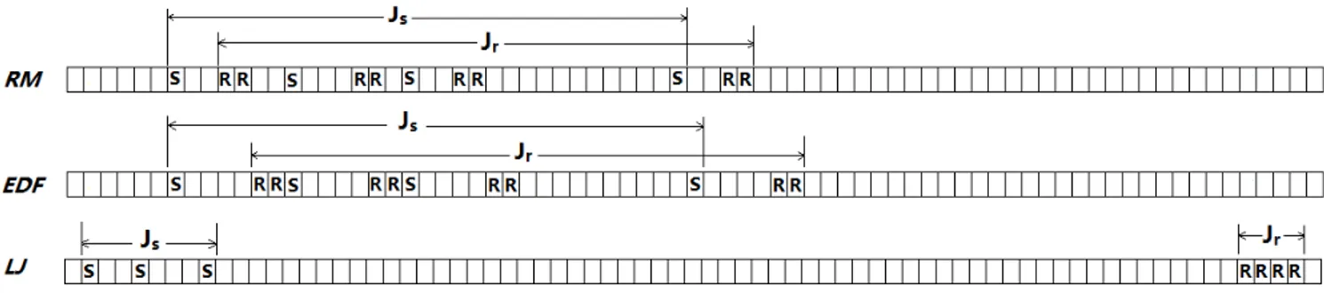
Fig. 2. Jitters of starting and ending slots in one superframe from node 15
Fig. 3. Jitter Comparison of Starting and Ending Slots
1.5 second. The maximum allowed hop number is defined as four. Half of the nodes in each network are sensors, whereas the other half are actuators.
For performance analysis, we only focus on one metric, namely the jitter. Since one hyperframe may contain several superframe for one task, after scheduling for each task we merge all superframes into one single superframe for jitter analysis. We define the starting slot and ending slot as the slots used by the starting and ending jobs respectively. Then we search for the earliest and latest position of the starting slot in this merged superframe. We define the interval between this two position as Js to be the starting slot jitter. Likewise the
ending slot jitter Jr can be found in the same way. Larger
values of Js and Jrare, the worse jitter performance will be.
B. Simulation Results and Analysis
We evaluate our Low Jitter Scheduling scheme, as well as RM and EDF scheduling scheme, in six different scenarios. First, we analyze the simulation results from one scenario with 15 nodes in detail. We take the scheduling result from one task, namely node 15, in this scenario for example. According to the refresh rate of this task, four superframes are included in one hyperframe. Thus, we merge these four superframe, overlapping with each other, in one superframe. Then we mark all the starting and ending slots in the superframe and compare Js and Jr of our scheduling scheme with those of RM and
EDF. The scheduling results, as well as all Js and Jr, for
this task is shown in Figure 2. In this figure, “S” indicates all starting slots, whereas “R” represents all ending slots. It is obvious that, for RM and EDF, both positions of starting and ending slots vary in a very wide range. However, for our proposed scheduling scheme, both starting and ending slots stay much closer with each other. The reason is that our scheduling scheme focuses on allocating starting and ending slots first. Before other slots being scheduled, the node collision problem is much less severe. Therefore, starting and ending slots will have more chances to be allocated at the fixed position in each superframe. It is also notable that the latency from our scheduling scheme is longer than RM and EDF. However, as we emphasized above, reducing latency in scheduling has very limited impact on improve the quality of control. Therefore, longer latency is acceptable. For the rest of nodes in this scenario, we calculate all jitters for starting and ending slots separately and summarize them in Figure 3. The jitters in this figure is called normalized jitter. Since different tasks may have different lengths of superframes, for fairly comparison between different nodes, we normalize Js
and Jr with the superframe length of each task. According
to the figure, it is significant that our scheduling scheme has much lower jitter for both starting and ending slots for all nodes in this scenario.
In order to prove our proposed scheduling scheme also performs better in general cases, we compare the jitters in all other five scenarios. Unlike the previous comparison, we combine Jsand Jras the overall jitter. The comparison results
are shown in Figure 4. It is notable that in the fifth subfigure,
there are only EDF and our scheduling scheme, because in this scenario RM fails to schedule all timeslots. It proves that our scheduling scheme does not sacrifice too much schedulability for lowing jitter. For some tasks, jitters are very low for all three scheduling scheme because of no node collision happened. According to the results, our scheduling scheme achieve much lower jitter than RM and EDF in all scenarios, which proves that our scheme also performs well in a general case.
V. CONCLUSIONS
In this paper, we first clarify two previous concerns about scheduling in IWSANs. We clarify the dependence of TDMA scheduling for sensors and actuators and point out the low correlation between the scheduling delay and the overall quality of control. Jitter reduction, as a new concern, is brought by us into scheduling for IWSANs to improve the quality of control. Afterward, we propose our scheduling scheme aiming for lowing jitter and compare it with two traditional real-time scheduling schemes, RM and EDF via simulation. The simulation results based on random network topologies demonstrate that our proposed scheduling scheme significantly outperforms the classic real-time scheduling schemes with lower jitter, which is extremely important for the overall control system.
REFERENCES
[1] E. Toscano and L. Lo Bello, “Multichannel superframe scheduling for ieee 802.15.4 industrial wireless sensor networks,” Industrial Informat-ics, IEEE Transactions on, vol. 8, no. 2, pp. 337–350, 2012.
[2] S. Han, X. Zhu, A. Mok, D. Chen, and M. Nixon, “Reliable and real-time communication in industrial wireless mesh networks,” in Real-Time and Embedded Technology and Applications Symposium (RTAS), 2011 17th IEEE, 2011, pp. 3–12.
[3] A. Saifullah, Y. Xu, C. Lu, and Y. Chen, “Real-time scheduling for wirelesshart networks,” in Real-Time Systems Symposium (RTSS), 2010 IEEE 31st, 2010, pp. 150–159.
[4] O. Chipara, C. Wu, C. Lu, and W. Griswold, “Interference-aware real-time flow scheduling for wireless sensor networks,” in Real-Time Systems (ECRTS), 2011 23rd Euromicro Conference on, 2011, pp. 67– 77.
[5] G. Fiore, V. Ercoli, A. Isaksson, K. Landernas, and M. Di Benedetto, “Multihop multi-channel scheduling for wireless control in wirelesshart networks,” in Emerging Technologies Factory Automation, 2009. ETFA 2009. IEEE Conference on, 2009, pp. 1–8.
[6] H. Li, P. Shenoy, and K. Ramamritham, “Scheduling messages with deadlines in multi-hop real-time sensor networks,” in Real Time and Embedded Technology and Applications Symposium, 2005. RTAS 2005. 11th IEEE, 2005, pp. 415–425.
[7] H. Zhang, P. Soldati, and M. Johansson, “Optimal link scheduling and channel assignment for convergecast in linear wirelesshart networks,” in Modeling and Optimization in Mobile, Ad Hoc, and Wireless Networks, 2009. WiOPT 2009. 7th International Symposium on, 2009, pp. 1–8. [8] (2010) Hart 7 specification, http://www.hartcomm.org/. [Online].
Available: http://www.hartcomm.org/
[9] Industrial society of automation, http://www.isa.org/.
[10] Shenyang institute of automation, http://www.industrialwireless.cn/. [11] K. Yu, M. Gidlund, J. Akerberg, and M. Bjorkman, “Reliable real-time
routing protocol for industrial wireless sensor and actuator networks,” in The 8th IEEE Conference on Industrial Electronics and Applications (ICIEA 2013), 2013.
[12] J. ˚Akerberg, M. Gidlund, and M. Bj¨orkman, “Future research challenges in wireless sensor and actuator networks targeting industrial automa-tion,” in IEEE 9th International Conference on Industrial Informatics (INDIN’11), July 2011.
5599