1
16
1987
Protective level of safety harnesses combined
with some racing car seats in frontal impacts
-a laboratory study
Anna-Lisa Ottoson, Swedish Road and Traffic Research
Institute, Linköping
Per Lövsund, Department of Traffic Safety, Chalmers
University of Technology, Göteborg
Reprint from Accident Analysis & Prevention, vol. 18,
No.6, pp. 483-494, 1986
v Vägal:/) Efi/( Statens väg- och trafikinstitut (VTI) * 581 01 Linköping [ St]tlltet Swedish Road and Traffic Research Institute * S$-581 01 Linkoping Sweden
Printed in Great Britain. © 1986 Pergamon Journals Ltd.
PROTECTIVE LEVEL OF SAFETY HARNESSES
COMBINED WITH SOME RACING CAR SEATS IN
FRONTAL IMPACTS A LABORATORY STUDY
ANNA-LISA OTTOSON
Swedish Road and Traffic Research Institute (VTI), 8-581 01 Linköping, Sweden and
PER LÖVSUND
Department of Traffic Safety, Chalmers University of Technology, S-412 96 Goteborg, Sweden Abstract As a basis for a prospective modification of the present seat-belt regulation in Sweden,
the protective level of safety harnesses compared with three-point belts has been studied.
Bio-mechanical tests were carried out with different combinations of belts and seats. The results showed that a three-point belt on a conventional seat offered the best protection in frontal impacts. The geometry of the safety harness (inverted Y-harness and four-point belt) induces the lap belt to slide over the iliac crest and the restraining force will be on the abdomen (submarining). This may be prevented by the use of a six-point belt, where two crotch straps keep the lap belt in position. The safety harness induces strong rebounds on the head, owing to the fact that the shoulder straps stop the forward motion of the torso too fast. High accelerations and HIC-values were registered for the head. The shoulder straps of the safety harnesses also expose the wearer s
shoulders and spine to high stresses in frontal impacts, which may induce injuries to the shoulders and compression injuries to the spine. Various solutions which may result in an increase of the protective level of the system safety harness and racing car seat in frontal impacts are discussed.
INTRODUCTION
In motor sport, types of seat belts are used differing from those in general traffic. Oc-casionally, opinions are expressed for the use of safety harnesses also in general traffic, although the requirements on protective equipment vary between motor sport and general traffic.
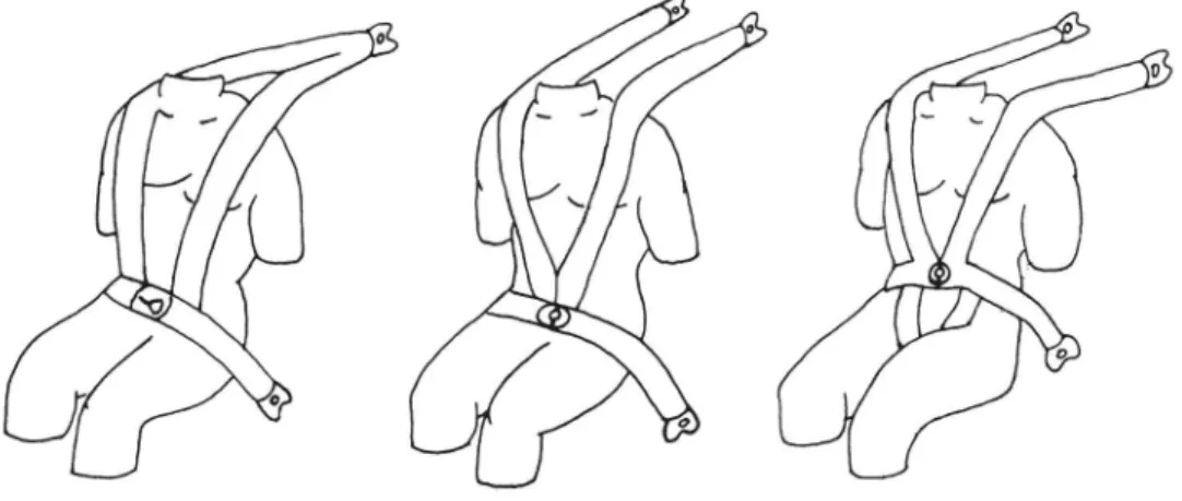
Safety harnesses are divided up on the basis of their design into three types (Fig. 1): (i) three point belts (inverted Y harnesses); (ii) four-point belts; (iii) six-point belts.
The primary function of the safety harness is to restrain the driver in his seat so that the vehicle can be controlled during high lateral accelerations as fast cornering, in addition to roll overs, i.e. under conditions other than those existing in normal traffic. The safety harness is designed so that it passes both shoulders and meets in the front at a central point, which means that shoulders and ribs are exposed to heavy loads in a collision. These areas are more easily injured than the stronger breastbone (sternum) which is not loaded at all when using a safety harness.
The function of the ordinary seat belt (the three-point belt) is to restrain the driver at hard braking and collisions. The diagonal strap is designed so that it mainly loads the breastbone (sternum). Since the upper anchorage point in the vehicle for the three-point belt is above shoulder height, the driver is not forced down in the seat when the seat belt tightens in a collision. The location of the anchorage point also prevents unnecessary loads on the shoulder. The lap strap lies over the pelvis and does not press upon the soft parts in the abdomen. The anchorage points for the lap strap are located so that the belt is prevented from sliding up into the abdomen. Hard components of the belt, such as buckles and adjusters, do not come into contact with the body when the belt is in use. However, the anchorage points for the three-point belt cannot normally be adjusted, which may lead to the belt loading other parts of the body than those intended in the
case of occupants over or under average height.
In motor sport, special seats are also used which provide more support for the sides of the body than normal seats. The seats are deeply bucketed, with high edges to the seat and back. They may also be fitted with a headrest and recesses for four point or six-point belts. The body is fixed to the seat and is prevented from sliding in any direction.
484 A.-L. OTTOSON and P. LÖVSUND
Fig. 1. (a) Inverted Y-harness. (b) Four-point belt. (c) Six-point belt.
The seats are frequently built on a frame of steel tube covered with hard, compact cushioning and with a firm base consisting of a plywood sheet which absorb some bumps and vibrations when the body is pressed heavily downwards in the seat towards the oor or the seat frame, when driving on rough surfaces. In recent years, a new model of racing-car seat has been developed. This is built on fibreglass, sometimes reinforced with Kevlar, which is a very strong, hard and light material. Fiberglass seats have a minimum of cushioning and weigh less than seats with frames of steel tubes.
Safety harnesses are most satisfactory and provide the best collision protection when
combined with a racing-car seat (States et al., 1970; ISO, 1984). A correctly fitted seat
with raised edges and recesses for a safety harness is considered to provide a significant degree of protection in the event of a frontal impact (Ardoino, 1984).
To obtain correct location of the lap strap of the safety harness over the pelvis, recesses must be provided in the seat so that the lap strap can be pulled through these. When using six-point belts, recesses must also be provided in the seat cushion for the crotch straps.
Injuries
The primary purpose of the three-point belt is to prevent or reduce personal injuries in collisions, hard braking or other incidents that may occur in general traffic. The three-point belt may itself cause injuries to the user, but these are often of only a limited nature and must be seen in relation to those which would have occurred if the belt had not been used.
The most common injuries arising from the three-point belt are fractures of the
clavicles, ribs and sternum. Contusions of those parts of the body where the straps have pressed against the skin also occurs, in addition to abrasion and tearing injuries, especially
around the neck and shoulders (e. g. Williams, 1970; Sabey et al., 1977; Nygren, 1984;
Backaitis and Dalmotas, 1985).
Injuries from safety harnesses can be divided into three categories; pressure injuries (mainly contusions), submarining and spinal injuries (Fulton, 1966; States and Ryon, 1969; States et al., 1970; States, 1980). Least serious are the pressure injuries from the straps which cause contusions and abrasions around the neck and shoulders, in addition to fractures of the clavicles and ribs. More serious injuries may occur when the lap strap slides away from its normal position over the pelvis and instead compresses the soft parts in the abdomen, an effect known as submarining. This introduces a risk of severe ab-dominal injuries, for example, the kidneys, liver, intestines and spleen may be deformed and ruptured. The spine may be injured by the shoulder straps causing pressure on the shoulder areas, if it is pressed down into the seat with accompanying compression. This is primarily the result of the rear attachment points for the safety harness being placed too low (Aldman, 1962; Fulton, 1966).
A safety harness combined with a normal car seat leads to severe submarining
provides more support for the body, the risk of submarining is considered to be reduced
(States et al., 1970; States, 1980; Ardoino, 1984).
Ardoino (1984) considers that the geometry of the four-point belt may lead to sub-marining. The shoulder straps tend to pull the whole device upwards when the belt is tightened, so that the lap strap is pulled up over the abdomen.
Collision tests with a three-point belt and safety harness respectively in combination
with various seats were made by Ardoino (1984). The tests showed that three point belts
in combination with a normal car seat provide the best protection in a frontal impact. In rally cars the six-point belt is stipulated, with two crotch straps to hold down the lap
strap.
Discussions have taken place in Sweden in recent years to gain approval for the use of safety harnesses also in general traffic. A pilot study has been made of the level of
protection afforded by safety harnesses compared to current three-point belts. Various
combinations of safety harnesses and seats were studied to determine whether they provide equivalent or better protection than three-point belts. For a detailed description of the
test method, the material and the results see Ottoson and Lovsund, 1985.
MATERIAL AND METHODS
The collision tests were made at the VTI biomechanical laboratory. In the studies a test trolley together with an instrumented anthropometric dummy (part 572) were used. Eleven collision tests were made with various combinations of belts and seats. The ex-periments were filmed with a high-speed camera and physical data were measured in each test.
The tests were performed with one make of safety harness, Klippan, which is one of the most common makes of safety harness for rally use in Sweden. The Klippan harness may also be marketed under other brand names. The harness is manufactured of low extensible (12%) webbing and has a central buckle with double adjustment (one front
and one rear) on each shoulder strap.
Tests were also made with ordinary three-point belts fitted with a Volvo automatic reel (17% extensibility) and with a simpler type of safety harness (Klippan) with a normal buckle and made of extensible webbing (17% extensibility).
Various makes and models of seats were tested in combination with the harnesses. Seats {with steel tube frames and also fibreglass seats were used, in addition to simpler models of racing-car seats without recesses. Other types tested were a Volvo seat and a
racing-car seat with adjustable back.
The seats were measured using an H-point dummy to determine whether different
types and makes of racing-car seats have different inclination of the back. Other geometric aspects were also studied, including geometry of the harness, but primarily measurements were made to check that the various seats were fitted in a similar manner. The mea surements were performed in accordance with ECE Regulation 14.
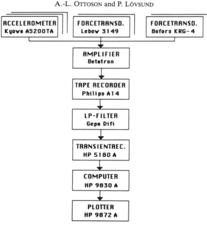
Electrical registrations were made for each test. The measuring system and its func-tion are shown in Fig. 2.
In safety harnesses, it is principally the forces in the shoulder straps that are of interest, since it is necessary to measure the load on the shoulder area and the rear attachment points in different combinations of harness and seat together with different rear attachment points for the shoulder straps. These load cells (LEBOW 3149) measure tensile forces directly and register forces up to 15 kN.
In the tests using the safety harnesses, a load cell was located on each shoulder strap between the dummy s shoulder and the rear attachment of the strap. In tests with normal seat belts, the tensile load in the strap between the automatic belt reel and the dummy s
shoulder was measured.
In a collision, the body is exposed also to vertical stresses which may cause spinal injuries. In order to measure these stresses, two load cells (BOFORS KRG-4) were located between the seat base and the floor, one on each side placed beneath the front
486 A.-L. OTTOSON and P. LÖVSUND
HCCELEROMETER FORCETBHNSD. FORCETHRNSD.
Kuova ASZOOTA Lebov 3149 Bofors KRG-4
[ I 1 $ RMPLIFIER Betatron
i
TRPE RECORDER Philips A14l
LP-FILTER Gapa Dii
TRRNSIENTREC. HP 5180 Ai
COMPUTER HP 9830 Al
PLOTTER HP 9872 AFig. 2. Measuring system.
The dummy was fitted with accelerometers (KYOWA, AS-200TA) in the head (CFC 1000 Hz), chest (CFC 180 Hz) and pelvis (CFC 180 Hz). These measure accelerations in the x, y and z axes with a range of 2000 +2000 m/s2 ( 200 + 200 g). The frequency range is 0 2000 Hz.
Using the measured values for acceleration in the head, the stresses to which the head is exposed can be calculated. The value is denoted HIC and is defined as
1 Iz 2.5
HIC = Max [( f a dt) (t2 [l)]
tZ _ tl tl
where a is the resulting acceleration; t1 and I2 are arbitrary times from that part of the acceleration curve for the head which has the highest amplitude.
The objective is to achieve a value as low as possible for HIC and a value of 1000 has been set as the maximum limit for the head. However, this value is criticised as being both too high and too low (Goldsmith and Ommaya, 1984).
The tests were filmed with a 16 mm high speed camera using a speed of 500 fps. The films were used for detailed study of the behaviour of the dummy, seat and harness in
the collision. The films also made it possible to measure the movements of the dummy
in the x-axis and the z-axis, thus providing a true measure of forward travel and vertical displacement of the dummy with the different harness and seat combinations.
In order to complement the other registrations with an indication of whether the lap strap had moved from its position over the pelvis to press against the soft parts of the abdomen, a plastic film containing air bubbles was used (Roberts and Lowne, 1984). Two rectangles (40 x 240 mmz) with 186 bubbles each were attached to the dummy s body from the pelvis up to the ribs. After the tests, a note was made of the number of air bubbles damaged.
The velocity of the test trolley, the retardation pulse and the stopping distance were also registered.
Protective level of safety harnesses 487
Table 1. Material Test
no. Belt Seat
1 Four point OMP steel tube racing car seat 2 Six-point RECARO PROFI fiber
glass racing car seat 3 Ordinary three- Vblvo seat
point belt
4 Ordinary three- COBRA simple racing-point belt car seat
5 Four point REGARD PROFI
fiber-glass racing car seat 6 Four-point COBRA simple racing
car seat
7 Four-point OMP steel tube racing-car seat with adjustable back
8 Simple four RALLY-ELIT steel tube point belt racing car seat 9 Four point RALLY ELIT steel tube
racing car seat 10 Four point RALLY ELIT fiberglass
racing car seat 11 Four point COBRA steel tube
racing-car seat
RESULTS
Test 1 was made with a retardation pulse in accordance with ISO 262E Draft Standard Safety Harness for dynamic testing of the safety harnesses. ISO 262E primarily contains recommendations for testing the strength of safety harnesses.
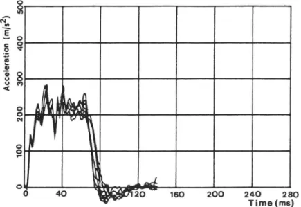
Figure 3 shows the retardation pulse of the test trolley for test 1. The peak value of the retardation pulse is 320 m/s2 (32 g) and its mean is approximately 250 m/s2 (25 g). The collision velocity was 50 km/h.
The retardation pulse in tests 2 11 is somewhat lower than in test 1 because of severe damages to the dummy, seat and harness. It corresponds to the pulse specified in ECE
Ac ce le ra ti on (m/s z) 40 0 5 0 0 20 0 30 0 100
_ &
4C) 12C) 240 280 Time (ms) 160 200
488 A.-L. OTTOSON and P. LÖVSUND 50 0 40 0 30 0 Ac ce le ra ti on (r n/ 32 ) 20 0 10 0
0 40 20 160 200 240 280 ' Time (ms)
Fig. 4. Deceleration curves, tests 2 11.
Regulation 16 for dynamic testing of seat belts. This pulse simulates a collision with a car designed with a rigid front.
A summary of the retardation pulses for the test trolley in tests 2 11 is given in fig. 4, where the curves are plotted over each other. The peak value for the retardation pulse is 270 m/s2 (27 g) and the mean is approximately 220 m/s2 (22 g). The collision speed was approximately 50 km/h for all tests.
At the moment of collision, the upper part of the dummy s body begins to move
forward and continues to do so until the harness retards this movement. Owing to elasticity in the harness, a rebound occurs, which causes the dummy to be forced backwards and downwards in the seat. This exposes primarily the head to large accelerations. Unless the lap strap counteracts further movement, the dummy will slide down in the seat and finally assume a supine position. The lap strap then tightens over the soft parts of the abdomen (Fig. 5).
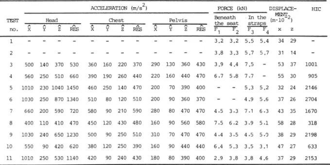
The measuring data from the tests are summarized in Table 2. For acceleration in
the head, chest and pelvis, the peak values are specified in the x, y and z axes and for
Protective level of safety harnesses 489
Table 2. Measurement data from the tests 2
ACCELERATION (m/s ) FORCE (kN) DISPLACE HIC
MENT Beneath »In the (nv10_2) TEST A AHeadA .A A AChesE A A Eelvii A the seat straps
no X Y Z RES X Y Z RES X Y Z RES F1 F2 F3 F4 x z
1 - - - 3.2 3.2 5.5 5.4 34 29 -2 - - - 3.8 3.3 5.7 5.7 31 14 -3 500 140 370 530 360 160 220 370 290 130 360 430 3.9 4.4 7,5 - 53 37 1001 4 560 250 510 660 390 190 260 440 220 160 440 470 6.7 5.8 7.7 - 55 30 905 5 1010 230 1040 1450 460 250 140 470 200 70 390 400 - 5.3 5.2 32 24 2146 6 1030 250 870 1340 510 80 120 510 200 90 360 370 4.9 5.6 37 26 2704 7 660 200 590 720 580 90 210 590 280 80 470 470 4.5 3.3 7.1 6.3 43 35 1670 8 400 110 410 470 450 120 430 480 160 90 560 580 7.5 6.2 3.9 5.1 58 28 318 9 1030 240 650 1230 500 90 250 510 310 70 470 470 4.4 3.5 4.5 5.0 38 29 2198 10 550 90 420 620 380 120 250 390 160 90 440 440 6.4 5.3 3.5 3.1 47 27 633 11 1010 250 530 1140 420 90 240 430 180 80 390 400 2.9 3.8 3.8 4.6 37 29 2153
the resultant stress. Peak values are also specified for vertical forces registered beneath the seat (F1, F2) and for forces (F3, F4) in the straps.
In tests 1 and 2, the measuring equipment did not operate satisfactorily for accel-eration measurements owing to a cable break. These data are therefore not documented. However, a comparison of the dummy s pattern of movement in retardation can be made for all tests by studying the high-speed film.
The measuring data for the remaining tests can be compared with the values for test 3 (ordinary three-point belt, Volvo seat) to obtain an idea of the normal case.
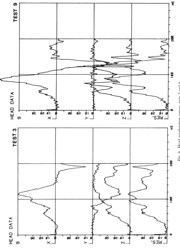
In Fig. 6 the head acceleration for test 3 (ordinary three-point belt) and 9 (four-point belt) is shown. It is obvious that the extensible four-(four-point belt causes higher stresses to the head than the three point belt.
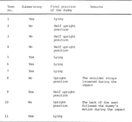
Through observations of the position of the lap strap on the dummy after the tests and comparisons with the film submarining and final position of the dummy for each collision test can be described (Table 3).
DISCUSSION
The study was made in order to obtain material for comparing the level of protection in frontal collisions between on the one hand, three-point belts in combination with a normal car seat and on the other, safety harnesses (mainly four-point and six-point belts) in combination with various racing car seats. A further objective was to use different measuring methods in quantifying the risks of submarining and spinal compression which earlier have been described by Aldman (1962) and Ardoino (1984), among others, and
to determine whether different combinations of harnesses and seats, or different methods
of fitting these, exerted an in uence on these risks.
From the measuring data in Table 2 and observations of the film, it has been found that the dummy s head was exposed to minimum loading in tests 3, 4, 8 and 10 (3. Three-point belt Volvo seat; 4. Three-Three-point belt simple racing-car seat; 8. Simple four-Three-point belt steel tube racing-car seat; 10. Four point belt fibreglass racing car seat). These tests show the lowest values for head acceleration in the x and z axes (the values in the y-axis are generally small) and acceptable HIC values (S 1000).
During the retardation sequence in the other tests, the dummy was thrown backwards in the seat and hit its head on the back of the seat. This rebound did not occur in tests 3, 4, 8 and 10, which explains the lower values for head acceleration and HIC. The upper part of the dummy s body travelled further forward (in the x-axis) in tests 3, 4, 8 and 10
:E
AD
DA
TA
TE
ST
3
:E
AD
DA
TA
T E S T 9åkt
(
W 38 53 cit m N __4>
S
* så a'e åt o
$an
Fi g.6. He ad ac ce le rati on cu rv es , te st s 3an d 9.Table 3. Final position
Test Subnarining Final position Remarks
no. of the dunmy
1 Yes Lying 2 No Half upright position 3 No Half upright position 4 No Half upright position 5 Yes Lying 6 Yes Lying 7 Yes Lying
8 No Upright The shoulder straps
position loosened during the impact
9 Yes Half upright
position
10 No Upright The back of the seat
position followed the dummy's motion during the impact
ll Yes Lying
than in the other tests. The rebound to which the dummy (primarily the head) was exposed was thus smaller in these tests.
Harness straps with high extensibility (l7%) were used in tests 3, 4 and 8. This may
explain the somewhat longer forward movement found in these tests compared to others. In these tests the large accelerations and recoil in the head were reduced. The head acceleration curves for test 8 showed acceptable peak values and HIC (Fig. 7). During the retardation sequence in test 8, the shoulder straps loosened owing to failure of the front adjusters, which further caused long forward movement of the upper part of the dummy s body.
In test 10, a fibreglass seat was used whose elasticity to a certain extent followed the driver s body forward and could thus absorb part of the energy during the rebound sequence. This may be a reason for the favourable result obtained in test 10.
The chest and pelvis were exposed to far lower accelerations than the head. The resulting acceleration of the chest was between 400 and 600 m/s2 (40 and 60 g) in all tests, which is acceptable according to biomechanical tolerances where the resulting ac-celeration for the chest is specified as max. 600 m/s2 (60 g) if the duration of the pulse is 23 ms (Sievert, 1979). If the duration of the pulse is less than 3 ms, higher values than 600 m/s2 (60 g) can be accepted (Faeber et al., 1976).
Test 2, performed with a six-point belt, shows low values for movement both in the
x- and z-axes. This is due to the fact that the six point belt is fitted with crotch straps, whose purpose is to restrain the dummy better in the seat and to prevent submarining. In the other tests, movement along the z-axis was approximately the same.
Vertical stresses (Fl, F2) occurring in a collision were measured beneath the front of the seat. This was done in order to get a measure of the compressive forces acting on the spine. Since the dummy s back changed direction to an unexpectedly large extent during the collision as a result of submarining, the centre of gravity moved forward. Consequently, the measured values for Fl and FZ cannot be regarded as representative of the stresses to which the dummy s back was exposed. The curves for F1 and F2 contain a positive and a negative peak, which is explained by the movement of the upper part of the body first forwards and then backwards. The rebound causes the head to hit the
back of the seat and break it. In tests 3, 4, 8 and 10, the force curves contain only one
492 A.-L. OTTOSON and P. LÖVSUND T HEAD DA A TEST 8 [ ' N 10 5 1i ; 301 RE S. w gu
l;
Fig. 7. Head acceleration curves, test 8.
peak (with high amplitude), which may be due to the lack of a severe recoil and sub-marining in these tests.
In test 8, the dummy remained in place because the shoulder straps loosened after half the sequence, which prevented the lap strap from sliding up into the abdomen, tightening over the pelvis instead. The fibreglass seat used in test 10 has a large inclination in the back and seat, which meant that the dummy sat low in the seat and could not slide forward with its pelvis.
The stresses (F3, F4) registered in the shoulder straps are a measure of the forces on the attachment points and on the shoulder area of the dummy. The force values obtained are generally of the same order of size in all the collision tests. The different location of the lap strap and the attachment points for the shoulder straps caused no significant difference.
To sum up, tests 4 and 10 show acceptable values, in addition to test 3 with a three-point belt and Volvo seat. There was no serious submarining or rebound in these tests. However, damage to the belts and seats did occur. In test 8, the shoulder straps loosened and in tests 4 and 10 the seat showed large deformations.
The cause of submarining may vary. The tests have shown that the greatest problem lies in the stresses in the shoulder straps, which pull the lap strap upwards and thereby allow the body to slide beneath it. In this sequence, the risk of spinal compression does not appear especially great. To prevent submarining in a racing car seat with a four-point belt, the seat cushion must either be given a greater inclination or provided with a depression to absorb more energy, at the same time as the lap strap must be prevented from sliding upwards through stresses from the shoulder straps.
Current six-point belts solve the problem of submarining by holding the lap strap in place. This instead moves the problem to the shoulders and introduces the risk of spinal compression. To reduce this risk, a positive effect may be obtained by choosing another
type of shoulder strap. Tests should be made on shoulder straps that together allow approximately the same extensibility as the diagonal strap in a normal three point belt, but without the risk of the user hitting the internal structures of the vehicle.
In some modern cars, protection is provided in front of the knees, which ought to eliminate or reduce the severe submarining effects registered. This introduces an increased
risk of knee or leg damage, since the knees will then absorb large stresses.
Further development of harnesses and seats should be accompanied by evaluation through new collision tests. Herebye, certain modifications should be made regarding the registration method.
The pattern of movement of the dummy varied considerably in the tests as a result of submarining etc. This means that the chosen measuring methods cannot be directly compared. The pattern of movement of the head follows that of the body, so that the registered head accelerations are to a certain extent in uenced by the rotation of the head.
In measuring the vertical forces beneath the seat it was intended to obtain a direct measure of spinal compression, but also here the measuring data were affected by the
varying position of the center of gravity of the dummy. To be able to study the effect of
various solutions to the problem of spinal compression, it is probably necessary to make direct measurements on the dummy s spine by registering force or extensibility.
The plastic sheet containing air bubbles was attached to the dummy s abdomen to quantify the submarining effect and has earlier been described by Roberts and Lowne, 1984. However, the method did not prove satisfactory and load cells applied to the dummy s iliac crest should be used instead.
CONCLUSIONS AND RECOMMENDATIONS
In this study, safety harnesses have been found to give poorer protection than the three-point belt in frontal impacts, with a high risk of injuries to the user s head, abdomen and spine.
The geometry of the safety harness leads to a high risk of submarining and consequent abdominal injury. Certain types of buckles have been found to cause further abdominal injury since the heavy, hard fittings of the central buckle penetrate the skin. The low extensibility of the shoulder straps contributes to a severe recoil effect on the head. The design of the harness causes the shoulder area, ribs and spine to be loaded injuriously.
On the basis of the study, safety harnesses as they are currently designed should not be recommended for use in general traffic, where the risk of frontal impacts is considerably greater than in the motor sport environment.
In motor sport, where the function of the safety harness is primarily to restrain the user in the seat in all situations, the safety harness may fill a purpose, but further de-velopment of both harness and seat could serve to increase safety.
Acknowledgements This study was sponsored by the Swedish Road Safety Office (TSV). The collision tests
were carried out in the biomechanical laboratories at the Swedish Road and Traffic Research Institute (VTI)
and assisted by Helge Lofroth, Ingemar Gustavsson and Ulf Zenöb. The views of Thomas Turbell (VTI) and Åke Sundberg (TSV) were of considerable use when planning the tests and analysing the results.
Address Correspondence: Dr. Per Lovsund, Dept. of Traffic Safety, Chalmers University of Technology, S
412 96 Goteborg, Sweden
REFERENCES
Aldman B. Biodynamic studies on impact protection. Acta Physiologica Scandinavia 56: Suppl. 192, Stockholm, 1962.
Ardoino P. L. Dynamics of the belted occupant, Implications for protection. In: Aldman B and Chapon A. (eds). The Biomechanics ofImpact Trauma. International Center for Transportation Studies. Elsevier Science Publishers, Amsterdam, 345 369, 1984.
Backaitis S. H. and Dalmotas D. Injury patterns and injury sources of unrestrained and three-point belt restrained car occupants in injury producing frontal collisions. Proc. 29th AAAM Annual Conf. Washington, DC, 365 391, Oct. 7 9, 1985.
Faeber E., Giilich H-A., Heger A. and Riiter G. Biomechanische Belastungsgrenzen Heft 3. Bundesanstalt fur Strassenwesen, Köln, 1976.
494 A.-L. OTTOSON and P. LÖVSUND
Fulton J. L. Seat belts versus shoulder harness. SAE technical paper series, 660536, 1966.
Goldsmith W. and Ommaya A. K. Head and neck injury criteria and tolerance levels. In: Aldman B and
Chapon A. (eds). The Biomechanics of Impact Trauma. International Center for Transportation Studies.
Elsevier Science Publishers, Amsterdam,_149 169, 1984.
ISO. Draft standard-safety harness. ISO/TC 22/ SC 12/WG AD HOC N11E, 1984.
Nygren A. Injuries to car occupants Some aspects of the interior safety of cars. A study of a five year material from an insurance company. Acta Oto-Laryngologia Suppl. 395, 1984.
Ottoson A-L. and Lövsund P. Safety harness Protective level for various combinations of belts and seats. VTI
Report 283. Swedish Road and Traffic Research Institute, Linköping, Sweden, 1985 (in Swedish). Roberts A. K. and Lowne R. W. An abdominal penetration detector for TNO child dummies. Transport and
Road Research Laboratory. Supplementary report 827, Crowthrone, Berkshire, 1984.
Sabey B. E., Grant B. E. and Hobbs C. A. Alleviation of injuries by use of seat belts. Proc. 6th Int. Conf. Int. Assoc. Accident in Traffic Medicine, Melbourne, 480 488, 1977.
Sievart W. Kenntnisstand der Biomechanischen Grenzwerte. In: Innere Sicherheit im Kraftfahrzeug. TuV-Reinland, Köln, 1979.
States J. D. Safety belts and seat design An inside from racing. Proc. 24th AAAM Annual Conf., Rochester, NY, 437 445, Oct. 7 9, 1980.
States J. D. and Ryon D. Restraint systems in racing accidents. SAE technical paper series, 690246, 1969.
States J. D., Snively G. and Fenner H. A. The medical aspects of driver protection systems and devices developed through automobile racing. SAE technical paper series, 700660, 1970.
Williams J. S. The nature of seat belt injuries. Proc. 14th Stapp Car Crash Conf., Michigan, 700896, 44 65,