http://www.diva-portal.org
Postprint
This is the accepted version of a paper presented at IEEE International Symposium on
Personal, Indoor and Mobile Radio Communications PIMRC 16, 04 Sep 2017, Valencia,
Spain.
Citation for the original published paper:
Tran, H V., Xuan Truong, Q., Tran, H-V., Uhlemann, E. (2017)
Optimal Energy Harvesting Time and Power Allocation Policy in CRN Under Security
Constraints from Eavesdroppers
In: IEEE International Symposium on Personal, Indoor and Mobile Radio
Communications PIMRC 16
N.B. When citing this work, cite the original published paper.
Permanent link to this version:
channel is the best after energy harvesting, and then use this one for communication without causing harmful interference to the PUs. Although, the energy harvesting in underlay CRN is a promising technique, it still has some disadvantages such as short range communication due to power constraints given by the PU. Also, the spectrum sharing in the underlay CRN may cause mutual interference between the SU and PU as the power allocation policies are not well designed. Moreover, this may lead to leakage of confidential information to the eaversdroppers (EAVs), who want to illegally exploit the communication in CRNs. To overcome the security problems in CRN, works reported in [12]–[14] have focused on solutions at the physical layer in order to reduce the risk of eavesdropping or jamming attacks. In [12], the authors consider a system model where a friendly jammer harvests energy from the RF of the sec-ondary transmitter (S-Tx) and then generates jamming signals to protect against EAV. Asymptotic closed-form expressions of the outage probability and the intercept probability for Nakagami-m fading channels have been obtained to analyze the system performance. In [15], an energy harvesting CRN in which multiple energy harvesting receivers may act as potential EAVs, was studied for small scale fading and path loss. Exact se-crecy outage probability was derived. In [14], a wireless energy harvesting CRN has been analyzed, wherein the SU harvests energy from a wireless power source and then uses it to transmit data opportunistically on an idle channel licensed to the PUs. However, the performance of the SUs in this CRN may be degraded very fast due to jamming attacks by malicious users. To overcome these issues, learning algorithms have been proposed to reduce negative effects from unfriendly jammers.
Although many interesting results have been published in RF energy harvesting for CRN, no one addresses the problem of utilizing the interference from multiple PUs to harvest the energy, reduce the affect of EAV, and at the same time enhance the reliability of the communication for CRNs. Therefore, in this paper, we study underlay energy harvesting CRN to not only en-hance spectrum efficiency and green energy utilization, but also guarantee a certain security constraint for the SU. In particular, we consider a CRN in which the SU can harvest energy radiated by multiple PUs operating in orthogonal channels and then uses this energy for communication. Here, the SU is overheard by multiple EAVs. To protect the confidential information of the SU from the EAVs and not to violate the interference constraint of the PU, the S-Tx must have a reasonable channel selection strategy and power allocation. Given these settings, the analysis for the considered CRN is twofold, namely as packet error probability and packet delay with retransmissions. Our main contributions are summerized as follows:
• An energy harvesting and communication protocol over multiple PU channels is proposed. Accord-ingly, an optimal energy harvesting time for the SU is derived.
• A power allocation policy and a channel selection strategy for the SU, which satisfy the interference constraint of the PU and its own security constraints for multiple EAVs is developed.
• To evaluate the system performance of the SU, closed-form expressions for the packet error proba-bility and packet delay including retransmission for the SU are derived.
The rest of this paper is structured as follows. In Section II, the system model, power constraints, and energy harvesting and communication protocol for the energy harvesting CRN are introduced. In Section III, the power allocation and channel selection strategy are analyzed. Further, an optimal energy harvesting time, and algo-rithm for power allocation and channel selection are pro-posed. In Section IV, closed-form expressions of packet error probability and packet delay with retransmissions are obtained. In Section V, the numerical examples and discussions are provided. Finally, conclusions are given in Section VI.
II. SYSTEM MODEL
In this section, the system model, and energy harvest-ing and communication protocol are presented.
A. System model and channel assumptions
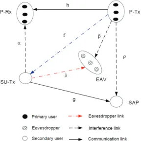
Let us consider a spectrum underlay CRN as shown in Fig. 1 in which N PUs are operating on orthogonal frequency bands, i.e., they do not cause interference to each other. The S-Tx harvests energy from N P-Txs and then uses this harvested energy to send packets to the secondary access point (SAP). Further, there exist K EAVs wishing to overhear the packet transmitted from the S-Tx to the SAP. Here, the SAP is equipped with M antennas while the others (P-Tx, primary receiver (P-Rx), EAV, and S-Tx) is assumed to have a single antenna. Channel gains of the P-Txn→P-Rxn and
S-Tx→SAP communication links are denoted hn, and gm,
n = 1, . . . , N , m = 1, . . . , M . Here, the channel gain gm is to represent the link from the S-Tx to the
m-antenna branches of the SAP. The channel gains of the P-Txn→EAVk, S-Tx→P-Rxn, P-Txn→SAP interference
links are denoted by βnk, αn, and ρnm, respectively. The
channel gains of the S-Tx→EAVs illegitimate links and the P-Txn→S-Tx energy harvesting links are expressed,
respectively, by δk and fn, k∈ {1, . . . , K}. We assume
that all channels are modeled as Rayleigh block flat fading, and the channel gains are random variables (RVs) distributed following exponential distribution. Ac-cordingly, the probability density function (PDF) and
Fig. 1. A system model of underlay CRN. The S-Tx scavenges the energy from multiple P-Tx and spends this harvested energy to deliver packet to the SAP. The S-Tx is overheard by multiple EAVs.
Fig. 2. A time frame T is used for energy harvesting and communica-tion. The time τ T is used to harvest energy from the multiple P-Txs, while the remaining time (1−τ)T is to deliver the packet to the SAP.
cumulative distribution function (CDF) are expressed, respectively, as fX(x) = 1 ΩX exp ( − x ΩX ) , (1) FX(x) = 1− exp ( − x ΩX ) , (2) where RV X ∈ {gm, hn, fn, αn, δk, βnk, ρnm}, refers
to the channel gain, and ΩX = E[X] is the channel
mean gain, i.e., Ωg = E[gm], Ωhn = E[hn], Ωαn =
E[αn], Ωδ = E[δk], Ωβn = E[βnk], Ωρn= E[ρnm].
B. Communication protocol
The basic idea of the RF energy harvesting in the considered CRN is that the S-Tx can convert the P-Tx emitted power, which is considered as harmful interfer-ence to the SU, into useful energy for the SU commu-nication. The total time used for energy harvesting and communication is showed in Fig. 2. Accordingly, the communication protocol is implemented in two steps as follows:
• Step 1: The S-Tx harvests the energy of N P-Tx over N wireless links fn, n ∈ {1, 2, . . . , N}.
The average harvested energy at the S-Tx can be expressed as follows: Es= E [ N ∑ n=1 θτ T Ppfn ] = θτ T PpE [ N ∑ n=1 fn ] , (3) where E[·], T , and τ are expectation, the total time frame, and a fraction of time frame used to harvest the wireless energy, respectively, 0 < τ < 1. Symbols Pp and θ represent the transmit power
of the P-Tx and the energy harvesting efficiency coefficient of the S-Tx, 0≤ θ ≤ 1.
• Step 2: After the energy harvesting process, the S-Tx also completes the channel state information (CSI) estimation, and it may know which is the best frequency band for the SU communication. Here, the best channel is the one that allows the S-Tx to use maximal transmit power to improve the performance. It is noted that the transmit power of the S-Tx in the remaining timeslot (1− τ)T and at the specific channel n-th is constrained by the harvested energy Es, i.e, P
(n) S−T x(1− τ)T ≤ Es. Accordingly, we have PS(n)−T x≤ Pavg= Es (1− τ)T = τ θPp 1− τ N ∑ n=1 Ωfn, (4) where Pavg is called as average power threshold
given by the S-Tx. On this basis, power allocation under various constraints and channel selection pro-cess for the SU can be derived.
III. POWER ALLOCATION AND CHANNEL SELECTION
OF THESU
In order to deliver packets to the SAP, the S-Tx firstly calculates the power allocation strategy in each channel to guarantee the quality of service (QoS) constraint of the PU and not reveal its confidential information to the EAVs.
1) Power constraint of the S-Tx under PU’s con-straint: Since the SU utilizes one of the N channels licensed to the PUs, its power control policy should be designed to not cause the harmful interference to the PU while obtaining the maximal power level to improve the performance. These can be interpreted into the outage probability constraint given by the PU ηp,
and the average power threshold given by the S-Tx as follows: Pr { Cp(n)≤ Rp } ≤ ηp, (5) PS(n)−T x≤ Pavg, (6)
where Rp, ηp, and Pavg are the target rate, outage
S-Tx, respectively. Symbol Cp(n)is the channel capacity
of the PU at the n-th frequency band, defined as Cp(n)= B log2
(
1 + γp(n) )
, (7)
where B is bandwidth and γp(n)is
signal-to-interference-plus-noise ratio (SINR) of the PU given as γp(n)= Pphn
PS(n)−T xαn+ N0
, (8)
in which the symbol N0 is noise power.
By substituting (8) and (7) into (5), we can rewrite (5) as follows Pr { Pphn PS(n)−T xαn+ N0 ≤ γp th } ≤ ηp, (9)
where γthp = 2RpB − 1. Further, using [16, Property 1],
the expression (9) can be calculated as
1− PpΩhn PS(n)−T xΩαnγ p th+ PpΩhn exp ( −γ p thN0 PpΩhn ) ≤ ηp (10) By setting An = γthpΩαn PpΩhn, Bn = γpthN0 PpΩhn, we can rewrite (10) as PS(n)−T x≤ 1 An [ exp(−Bn) 1− ηp − 1 ] . (11)
Combining (11) with (6), the transmit power of the S-Tx should satisfy both PU’s outage constraint and its own harvested energy as PS(n)−T x≤ min { PP U(n), Pavg } , (12) where PP U(n) is formulated as PP U(n)= 1 An [ exp(−Bn) 1− ηp − 1 ] . (13)
2) Power constraint of the S-Tx under the overhearing of multiple EAVs: The confident communication of the SU is threaten by K EAVs. Therefore, the S-Tx should regulate its power to not reveal the information to the EAVs. This can be interpreted into the outage security and transmit power constraints of the S-Tx as follows
Pr { max k∈{1,...,K} { Ce(n,k) } ≥ Re } ≤ ξ, (14) PS(n)−T x≤ Pavg, (15)
where Re and ξ are the secrecy target rate and the
secrecy outage constraint, respectively. Symbol Ce(n,k)
denotes the channel capacity of the EAVk over the
S-Tx→EAVk link when the S-Tx selects the frequency
band n to transmit, defined as
Ce(n,k)= B log2
(
1 + γe(n,k) )
, (16)
in which γe(n,k) is the SINR of the EAVk at the n-th
frequency band, and it can be approximated as
γe(n,k)= P (n) S−T xδk Ppβnk+ Ne ≈ PS(n)−T xδk Ppβnk , (17) where Ne is noise power at the EAVs. The
approxima-tion (17) is understood that the interference from the P-Tx to the EAV is much larger than the background noise power, i.e. Ppβnk>> Ne, and the EAVs only are
affected by the interference from the P-Tx. Substituting (16) into (14), we have Pr { max k∈{1,2,...,K}{B log2 (1 + γe(n,k))} ≥ Re } ≤ ξ. (18) Since all channels are independent random variables, the expression (18) can be formulated as
1− K ∏ k=1 Pr { δk βnk ≤ γe thPp PS(n)−T x } | {z } I ≤ ξ, (19)
where γeth = 2ReB − 1. Further, the probability in (19)
can be derived as I = ∞ ∫ 0 Pr { δk≤ xγe thPp PS(n)−T x } fβnk(x)dx, (20) where fβnk(x) = 1 Ωβn exp ( − x Ωβn ) . Accordingly, the integral I can be calculated as
I = 1− ∞ ∫ 0 1 Ωβn exp [ − ( γe thPp PS(n)−T xΩδ + 1 Ωβn ) x ] dx = 1− γe 1 thPpΩβn PS−T x(n) Ωδ + 1 . (21)
Substituting (21) into (19) and after some mathematical manipulations, we obtain the power constraint for the S-Tx to against multiple eavesdroppers as follows
PS(n)−T x≤γ e thPpΩβn(1− K√1− ξ) Ωδ K √ 1− ξ . (22)
Combining (22) with the energy harvesting constraint (15) yields PS(n)−T x≤ min { PEav(n), Pavg } , (23)
where PEav(n) is expressed as
PEav(n) =γ e thPpΩβn(1− K √ 1− ξ) Ωδ K √ 1− ξ (24)
As a consequence, the transmit power of the S-Tx in the n-th channel is obtained by combining (12) with (23) as
PS(n)−T x= min {
min{PP U(n), PEav(n)}, Pavg
}
From (25), we consider two case as follows:
• Case 1: Pavg > min{P
(n)
P U, P
(n)
Eav}, the transmit
power of the S-Tx depends on the joined constraints of the PU and EAV as
PS(n)−T x= min{PP U(n), PEav(n)}, (26) where PP U(n)and PEav(n) are defined in (13) and (24), respectively. Note that if the energy harvesting time τ in this case is increase further, the transmit power of the S-Tx can not increase further due to the joint constraint of the PU and EAVs.
• Case 2: Pavg ≤ min{P
(n)
P U, P
(n)
Eav}, the
maxi-mal transmit power of the S-Tx depends on the harvested energy from the PUs, i.e., PS(n)−T x = Pavg. Moreover, the S-Tx expects to have a high
value of Pavg to obtain the high performance, this
leads to a fact that the maximal Pavg is equal to
min{PP U(n), PEav(n)}, i.e., Pavg = min{P
(n)
P U, P
(n)
Eav}.
After some mathematical manipulations, we obtain the optimal energy harvesting time τ for maximiz-ing the value of Pavg as
τ∗= min{P (n) P U, P (n) Eav} θPp ∑N n=1Ωfn+ min{P (n) P U, P (n) Eav} . (27) Moreover, the S-Tx wants to select the best channel to maximize its transmit power to improve its performance, and this is given as
n∗= arg max n∈{1,2,...,N} { PS(n)−T x } , (28)
where n∗ is the selected channel such that the transmit power of the S-Tx is optimal, i.e.,
PS(n−T x∗) = max
n∈{1,2,...,N}
{ min
{
min{PP U(n), PEav(n)}, Pavg
}} . Finally, an algorithm for the power allocation and channel selection is shown in Algorithm 1.
Algorithm 1 Power allocation and channel selection
1: procedure PASA 2: PS(n−T x∗) := 0; 3: for{n = 1; n ≤ N; n + +} do 4: PP U(n)=An1 [ exp(−Bn) 1−ηp − 1 ] ; 5: PEav(n) =γ e thPpΩβn(1−K√1−ξ) ΩδK√1−ξ ; 6: τ = min{P (n) P U,P (n) Eav} θPp∑Nn=1Ωfn+min{PP U(n),P (n) Eav} ; 7: Pavg= τ θPp 1−τ ∑N n=1Ωfn; 8: PS(n)−T x= min {
min{PP U(n), PEav(n)}, Pavg
} ; 9: if PS(n)−T x≥ PS(n−T x∗) then 10: n∗= n; 11: PS(n−T x∗) = PS(n)−T x return n∗ and PS(n−T x∗) ;
IV. PERFORMANCEANALYSIS
When the S-Tx sends packets, they may be in error due to channel impairment and other factors. Thus, the S-Tx needs to recharge and retransmit. In order to measure this process, we will consider two performance metrics, called packet error probability (PEP) and average packet delay (APD), as follows:
1) Packet Error Probability: The PEP is defined as the probability that the SINR of the SU drops below a predefined threshold, i.e.,
O = Pr {γs≤ γth} , (29)
where γth is the SINR threshold of the SU and γs is
defined as γs= max m∈{1,2,...,M} { PS(n−T x∗) gm Ppρn∗m+ N0 } . (30)
Accordingly, the PEP can be calculated by using order statistics and the help of [16, Property 1] as follows:
O = Pr { max m∈{1,2,...,M} { PS(n−T x∗) gm Ppρn∗m+ N0 } < γth } = M ∏ m=1 Pr { PS(n−T x∗) gm Ppρn∗m+ N0 < γth } = 1 − exp ( − γthN0 PS−T x(n∗ ) Ωg ) γthPpΩρn∗ PS(n∗ )−T xΩg + 1 M . (31)
2) Packet Delay With Retransmissions: when a packet is transmitted unsuccessfully, the S-Tx needs to recharge the energy and then retransmit. The probability that a packet is transmitted successfully after ℓ transmissions is expressed as follows:
Pr{L = ℓ} = Oℓ−1(1− O), (32) where L is the number of transmissions. Accordingly, the average number of transmissions per packet can be calculated as E[L] = ∞ ∑ ℓ=1 ℓOℓ−1(1− O) = 1 1− O. (33) Finally, the average delay to transmit a packet can be calculated as follows:
D = T E[L] = T
1− O, (34)
where T is total time frame and O is PEP defined in (29).
V. NUMERICAL RESULTS
In this section, we present numerical examples for the considered system. In particular, we investigate the impact of the P-Tx transmit signal-to-noise ratio (SNR), energy harvesting time, and the channel mean gains on the PEP and APD. Unless otherwise stated, the following system parameters are used for both analysis and simula-tion: System bandwidth: B = 2 MHz; Outage constraint of PU: ηp= 0.01; Security constraint: ξ = 0.01; Energy
harvesting coefficient efficiency: θ = 0.5; Target rate of SU, PU, and EAVs are Rs= 64 Kbps, Rs= 64 Kbps,
and Re= 3 Mbps, respectively.
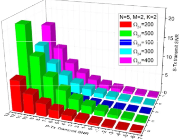
Fig. 3 illustrates the impact of channel mean gains of the P-Tx→EAVs links (Ωβn) on the S-Tx transmit
SNR. We can see that the index C, which is equivalent to the channel 2 and Ωβ2 = 500, provides the highest
S-Tx transmit SNR. On the other hand, the index D, which is equivalent to the channel 3 and Ωβ3 = 100,
provides the lowest S-Tx transmit SNR. This is due to the fact that a higher channel mean gain of the P-Tx→EAVs leads to a stronger interference to the EAVs, i.e., the EAVs experience difficulties to decode the transmitted packet from the S-Tx. As a result, the S-Tx can increase its transmit power to enhance its performance without leaking confidential information to the EAVs. In other words, channel 2 will be selected for the SU communication. This phenomenon can be observed from Fig. 3, i.e., increasing the channel mean gains of the P-Tx→ EAVs links (Ωβn) leads to scaling
up of the P-Tx transmit SNR, or the interference from the P-Tx to the EAVs brings benefit for the S-Tx transmit SNR.
Fig. 5 shows the impact of the fraction of the energy harvesting time τ and channel mean gains of P-Tx →S-Tx energy harvesting links {Ωfn}
5
n=1 = 1, 3, 5 on the
S-Tx transmit SNR. It can be seen that when the channel mean gain of the P-Tx→S-Tx harvesting link is the
Fig. 3. Impact of channel mean gains of the P-Tx→EAVs links (Ωβn)
on the S-Tx transmit SNR. -6 -4 -2 0 2 4 6 8 10 12 -24 -20 -16 -12 -8 -4 0 4 8 S -T x T r a n s m i t S N R ( d B ) P-Tx Transmit SNR (dB) N=5, M=2, K=2 n =10 n =50 n =80 n =150
Fig. 4. The S-Tx transmit SNR versus the P-Tx transmit SNR with increasing channel mean gains of the S-Tx→EAV link {Ωβn}
5 n=1= 10, 50, 80, 150. 0.0 0.1 0.2 0.3 0.4 0.5 -6 -4 -2 0 2 4 6 8 10 12 14 S -T x T r a n s m i t S N R ( d B ) N=5, M=2, K=2 fn =1 fn =3 fn =5
Energy Harvesting Time, Optimal point for energy harvesting time
Fig. 5. The SU transmit SNR versus the energy harvesting time τ and the channel mean gains of P-Tx→S-Tx energy harvesting links
{Ωfn} 5 n=1= 1, 3, 5, and γP−T x= 12 dB. highest, i.e., {Ωfn} 5 n=1 = 5, the S-Tx transmit SNR is
increased very fast and saturated at τ = 0.1. Also, all S-Tx transmit SNR is saturated at the same value 13 dB as τ > 0.4, i.e., the energy harvesting time does not affect the S-Tx transmit SNR. This can be explained as follows: the higher channel mean gain of the P-Tx→S-Tx link leads to a higher energy harvested from the P-Txs, thus the time consumed τ to harvest the energy is shorter. However, increasing the energy harvesting time further, i.e. τ > 0.4, the S-Tx cannot harvest more energy due to the fixed transmit SNR of the P-Txs γP−T x= 12 dB,
i.e., the S-Tx transmit SNR is saturated.
Fig. 6 shows the impact of the P-Tx→EAV interfer-ence links on the PEP by consider the following cases:
• Case 1: Channel mean gains of the P-Tx→EAVs interference links are identical:{Ωβn}
5
n=1= 10; • Case 2: Channel mean gain of from the
P-Tx5→EAVs interference links is the highest: Ωβ5=
50, the other is identical:{Ωβn}
4
n=1= 10; • Case 3: Channel mean gain of from the
P-Tx1→EAVs interference links is the highest: Ωβ1=
100, the other is identical:{Ωβn}
4
n=2= 10; • Case 4: Channel mean gains of the P-Tx→EAVs
-6 -4 -2 0 2 4 6 8 10 12 10 -5 10 -4 10 -3 10 -2 10 -1 10 0 P a c k e t E r r o r P r o b a b i l i t y P-Tx Transmit SNR Ana. Case 1: { n } 5 n=1 =10 (Sim.) Case 2: 5 =50, { n } 4 n=1 =10 (Sim.) Case 3: 1 =100, { n } 4 n=2 =10 (Sim.) Case 4: { n } 5 n=1 =10, M=3 (Sim.) N=5, K=2, M=2
Fig. 6. Channel mean gain of P-Tx→P-Rx links: {Ωhn}
5
n=1= 2;
Channel mean gain of S-Tx→P-Rx links: {Ωαn}5n=1= 2; Channel
mean gain of P-Tx→S-Tx links: {Ωfn}
5
n=1= 5; Channel mean gain
of S-Tx→EAVs links: {Ωδk}2k=1 = 1; Channel mean gain of
P-Tx→SAP links {Ωρnm} = 1 for all n and m; Channel mean gain of
S-Tx→SAP links Ωg= 8;.
interference links are identical as in Case 1. But the number of antennas of the SAP is greater than the one of Case 1, i.e., M = 3.
It can be seen from Case 1 to Case 3 that if one of the channels has the strongest P-Tx→EAV interference links, it is selected for communication and the PEP is degraded significantly. More specifically, the PEP in Case 3 is better than the one in Case 1 and Case 2. This can be explained by the fact that the strong interference from the P-Tx to the EAVs degrades the quality of packets decoded at the EAVs. Accordingly, the S-Tx can increase its transmit SNR to enhance its performance without leaking confidential information to the EAVs. Further, we see that the PEP in Case 4 is better than the one in Case 1. Because the number of antennas of the SAP in Case 4 is higher than Case 1, and hence its received signal is better than Case 1. As a result, the PEP in Case 4 is reduced.
Fig. 7 shows the impact of the S-Tx→EAVs and S-Tx→SAP links on the packet delay. We can see that at the low P-Tx transmit SNR regime, e.g. γP−T x <−2
dB, the packet delay goes to infinity. However, as the P-Tx transmit SNR increases further, the packet delay of the SU is reduced significantly. This is because the S-Tx only harvests small amounts of energy at the low P-Tx transmit SNR, thus the power required to deliver the packet is very low, which increases the packet error rate. Hence, the S-Tx requires several retransmissions to deliver the packet, i.e., the packet delay increases. Further, as the channel mean gain of the S-Tx→EAVs links increase from Ωδ = 2 to Ωδ = 6, the packet
delay also increases. This is due to the fact that the EAVs can decode the packet from the S-Tx more easily as the channel mean gain of the S-Tx→EAVs links increase. To guarantee secure communication, the S-Tx must reduce its transmit SNR to satisfy the se-curity constraint. Accordingly, the packet error rate is
-6 -4 -2 0 2 4 6 8 10 12 0.02 0.04 0.06 0.08 0.10 P a c k e t D e l a y ( S e c o n d s ) P-Tx Transmit SNR N=5, K=2, M=2 Ana. g (Sim.) g (Sim.) g (Sim.)
Fig. 7. Packet delay versus P-Tx transmit SNR. Channel mean gain of P-Tx→P-Rx links: {Ωhn}
5
n=1 = 2; Channel mean gain of
S-Tx→P-Rx links: {Ωαn}5n=1= 2; Channel mean gain of P-Tx
→S-Tx links:{Ωfn}
5
n=1= 5; Channel mean gain of P-Tx→EAVs links:
{Ωβn}5n=1= 2; Channel mean gain of P-Tx→SAP links {Ωρnm} =
1 for all n and m; Channel mean gain of S-Tx→SAP links Ωg= 5;.
increased, i.e., the S-Tx requires more retransmissions. Thus, the packet delay increases. It also can be seen that as the channel mean gain of the S-Tx→SAP link increases from Ωg = 5 to Ωg = 10, the packet delay
is improved significantly. It is easy to understand that as all constraints are satisfied, a strong channel gain between the source and the destination will guarantee a low packet error rate, i.e, the S-Tx does not have to retransmit the packet.
VI. CONCLUSIONS
In this paper, we have proposed an energy harvesting and communication protocol for CRNs, in which the S-Tx is subject to the harvested energy constraint, security constraints due to multiple EAVs, and outage probability constraint of the PU. The optimal energy harvesting time, a power allocation policy and a channel selec-tion strategy have been derived. Moreover, performance analysis in terms of packet error probability and average packet delay including retransmissions for the secondary network has been obtained. Further, our numerical re-sults show that the proposed power allocation policy and channel selection strategy can provide reliable and secure communication for the SU without violating the security constraints and interference constraints due to multiple PU. Finally, the analytical results are verified by simulations.
ACKNOWLEDGEMENT
The research leading to these results has been per-formed in the SafeCOP project which is funded from the ECSEL Joint Undertaking under grant agreement n0 692529 and from National funding, and the research project of Ministry of Education and Training, Vietnam (No.B2017-TNA-50).
REFERENCES
[1] X. Lu, P. Wang, D. Niyato, D. I. Kim, and Z. Han, “Wireless networks with RF energy harvesting: A contemporary survey,”
IEEE Communications Surveys Tutorials, vol. 17, no. 2, pp. 757–
789, Secondquarter 2015.
[2] S. Sudevalayam and P. Kulkarni, “Energy harvesting sensor nodes: Survey and implications,” IEEE Communications Surveys
Tutorials, vol. 13, no. 3, pp. 443–461, Third 2011.
[3] C. Zhong, X. Chen, Z. Zhang, and G. K. Karagiannidis, “Wireless-powered communications: Performance analysis and optimization,” IEEE Transactions on Communications, vol. 63, no. 12, pp. 5178–5190, Dec. 2015.
[4] J. Guo, S. Durrani, X. Zhou, and H. Yanikomeroglu, “Outage probability of ad hoc networks with wireless information and power transfer,” IEEE Wireless Communications Letters, vol. 4, no. 4, pp. 409–412, Aug. 2015.
[5] R. Zhang and C. K. Ho, “MIMO broadcasting for simultaneous wireless information and power transfer,” IEEE Transactions on
Wireless Communications, vol. 12, no. 5, pp. 1989–2001, May
2013.
[6] W. Chung, S. Park, S. Lim, and D. Hong, “Spectrum sensing op-timization for energy-harvesting cognitive radio systems,” IEEE
Transactions on Wireless Communications, vol. 13, no. 5, pp.
2601–2613, May 2014.
[7] D. T. Hoang, D. Niyato, P. Wang, and D. I. Kim, “Opportunistic channel access and RF energy harvesting in cognitive radio networks,” IEEE Journal on Selected Areas in Communications, vol. 32, no. 11, pp. 2039–2052, Nov. 2014.
[8] S. Lee, R. Zhang, and K. Huang, “Opportunistic wireless energy harvesting in cognitive radio networks,” IEEE Transactions on
Wireless Communications, vol. 12, no. 9, pp. 4788–4799, Sep.
2013.
[9] V. Rakovic, D. Denkovski, Z. Hadzi-Velkov, and L. Gavrilovska, “Optimal time sharing in underlay cognitive radio systems with RF energy harvesting,” in IEEE International Conference on
Communications (ICC), Jun. 2015, pp. 7689–7694.
[10] S. A. Mousavifar, Y. Liu, C. Leung, M. Elkashlan, and T. Q. Duong, “Wireless energy harvesting and spectrum sharing in cognitive radio,” in IEEE Vehicular Technology Conference, Sep. 2014, pp. 1–5.
[11] Z. Yang, Z. Ding, P. Fan, and G. K. Karagiannidis, “Outage per-formance of cognitive relay networks with wireless information and power transfer,” IEEE Transactions on Vehicular Technology, vol. 65, no. 5, pp. 3828–3833, May 2016.
[12] P. M. Quang, T. T. Duy, and V. N. Q. Bao, “Performance evaluation of underlay cognitive radio networks over
Nakagami-m fading channels with energy harvesting,” in International Con-ference on Advanced Technologies for Communications (ATC),
Hanoi, Vietnam, Oct. 2016, pp. 108–113.
[13] L. Jiang, H. Tian, C. Qin, S. Gjessing, and Y. Zhang, “Secure beamforming in wireless-powered cooperative cognitive radio networks,” IEEE Communications Letters, vol. 20, no. 3, pp. 522–525, Mar. 2016.
[14] D. T. Hoang, D. Niyato, P. Wang, and D. I. Kim, “Performance analysis of wireless energy harvesting cognitive radio networks under smart jamming attacks,” IEEE Transactions on Cognitive
Communications and Networking, vol. 1, no. 2, pp. 200–216,
June 2015.
[15] A. Singh, M. R. Bhatnagar, and R. K. Mallik, “Secrecy outage of a simultaneous wireless information and power transfer cognitive radio system,” IEEE Wireless Communications Letters, vol. 5, no. 3, pp. 288–291, Jun. 2016.
[16] H. Tran, H. J. Zepernick, and H. Phan, “Cognitive proactive and reactive DF relaying schemes under joint outage and peak transmit power constraints,” IEEE Commun. Lett., vol. 17, no. 8, pp. 1548–1551, August 2013.