AVOIDABLE COLLISION CONTROLS UNDER A CONNECTED AND
AUTONOMOUS VEHICLES ENVIRONMENT
Sangung Park University of Seoul
Room 533, 21st hall, University of Seoul, 163 Seoulsiripdaero, Dongdaemun-gu, Seoul 02504, KOREA Phone: +82-6490-5661 E-mail: hazsang@naver.com
Co-author : Seungjae Lee, University of Seoul ; Jooyoung Kim*, University of Seoul
1.
INTRODUCTION
Because all travelers want an efficient and comfortable trip, many engineers and researchers related to automotive technologies have improved their technologies. Two important technologies, connected vehicle environment(CV environment) and autonomous vehicles(AV), are considered to satisfy two properties, which are called ADAS(Advanced Driver assistance system). CV communicates with other vehicles, vehicle management, and connection to other advanced technologies under radio communication environment and shows driver various information of road condition, accident warning, traffic congestion prediction, and nearby vehicle’s kinematic information. While, sensors of AV recognizes nearby information through innate various sensors, called sensor fusion(Anderson, J.M. et al., 2014 ; Litman, T. 2014 ; Svensson L. & Eriksson, J., 2015) and judge the next path.(Dolgov, D. et al., 2010).
However, these two technologies have their own weakness. CV shows too much information so drivers can’t embrace all information and have many difficulties of judging the driver’s behavior properly. Range of AV’s sensor is nearly the same as the range of vision (Weiß, C., 2011) so AV can’t perceive macroscopic traffic flows. To compensate the defect, automotive technologies tend to be the integrated technologies of connected environment and autonomous vehicles, called connected and autonomous vehicles(CAVs)(Parnet, M., 2013 ; Talebpour and Mahmassani, 2016).
CAVs judge and drive themselves by using the vehicle and road information through the CAV environment and/or vehicle sensors. Among CAV technologies, this paper concentrate on two main technologies: Adaptive cruise control(ACC) and cooperative adaptive cruise control (CACC), which is related to collision controls. ACC and CACC keep the time headway between an ego vehicle and a following vehicle (Milanes and Shladover, 2014;Jia and Ngoduy, 2016). Therefore, the complexity and diversity of the information obtained by CAVs have resulted in the combination of many sensitive components.
The combination of many sensitive components, which is related to reliability of technologies, causes CAVs malfunction. Malfunction of CAVs can normally affect vast harm of travelers so various safety standards are adopted to check the safety and minimize the malfunction. Many skeptics of CAVs raise a question about the reliability of CAVs. Therefore, CAV has to adopt its own safety standards. Automotive safety integrity level(ASIL) is a risk evaluation standard for only autonomous vehicles defined by the ISO 26262 – functional safety for road vehicles standard(National instruments, 2012). ASIL is the combination of severity, exposure and controllability.This is a new adaptation of the safety
integrity level(IEC 61508) for the automotive industry. ASIL is classified from A(Lowest safety) to D(Highest safety). ASIL D refers to the highest classification of initial hazard and to that standard’s most stringent level of safety measures to apply for avoiding an unreasonable residual risk.
This paper proposes theoretical methods to suggest proper time headway range by velocity to prevent collision controls. This paper formulates time-invariant headway and evaluates the proper headway range of CAV technologies using string stability theory. We simulate three available cases (No ADAS, ACC, and CACC cases) to investigate effects of the malfunction of CAV’s two main technologies (ACC and CACC). The contribution of this paper is to simulate proper headway range and time-invariant failure probability under CAV environment
2.
PRECEDENT RESEARCH
CAV has many components to function properly so SAE international defines six levels of automation, relative to a base level (Level 0) of no automation, with Level 5 of high automation(SAE international, 2014). In this level, high automation doesn’t need the takeover request time which only needs when conditional automation, level 3. Therefore, in this paper we assume that CAV has automotive technologies of level 3. Level 3, conditional automation, defines “the driving mode-specific performance by an automated driving system of all aspects of the dynamic driving task with the expectation that the human driver will respond to a request to intervene.”
NHTSA defined driver vehicle interface(DVI) technology as the interface between driver and vehicle’s components. DVI technology contains important components, i.e. recognition of the inner environment, emergency warning and takeover request time(Green, P., 2008). Most researchers agreed that takeover request time range is very critical to keep safe headway range of CAVs(Althoff, M., & Mergel, A., 2011). Fig. 1 depicts takeover request time range. Takeover request time is defined as the time from transition step and takeover request time step in this Fig. 1.
Figure 1: Minimum prediction time to secure transition quality.
Compared with the takeover request time, traditional perception-reaction time is required. Traditional perception-reaction time to design stopping sight distance at Policy on geometric design of highways and streets is 2.5 seconds, which means the 90th percentile of reaction time for all drivers (AASHTO, 2001). This paper considers perception-reaction time(𝑇𝑟) as lognormal distribution of unrecognized stop
of precedent vehicle by Lerner’s theory of perception-reaction time theory(1995)( 𝝀 as 0.17, 𝝃 as 0.44)(C.J. Messer et al.,1997). Average of perception-reaction time is 1.31 seconds with 0.6seconds of standard deviation, 50th perenctile as 1.19seconds, 85th perecnetile as 1.87seconds, 95th percentile as 2.45seconds.
Various driving technologies, Human drivers or CAV technologies, determine proper time headway (Vanholme et al., 2013). Vanholme et al.(2013) proposes legal safety by legislating various safety rules. In detail, length of takeover request time range determines the safe headway range of CAV technologies.
To keep safe time headway, stability of time headway distribution is proposed. Many researchers know the importance of time headway distribution (Badhrudeen et al.,2016; Pueboobpaphan, R. et al.,2013). However, keeping safe time headway doesn’t guarantee safety of behavior due to the fact that dangerous situation always happens at the outlier point. Therefore, we can say the safe time headway range by stability analysis of time headway to keep safety.
3.
METHODOLOGY
Microscopic simulation is needed to simulate level 3 CAVs. This paper selects Intelligent driver model(IDM) for the performance of technologies to keep time headway. most commonly used for realistic acceleration model. (Treiber and Kesting, 2013; Treiber and Kesting, 2017) Equ. 1 depicts its model. It contains ratio of vehicle speed to desired speed and ratio of desired space gap to real space gap. In this equation 1, 𝑎 is the maximum acceleration of a vehicle(𝑚/𝑠2), 𝑣
0 is the desired speed of a
vehicle(m/s), δ is the free acceleration exponent, 𝑠(𝑡) is the space gap(m) at time 𝑡 , 𝑠0 is jam
distance(m), T is desired time gap(sec), and Δt is the simulation time step(sec).
𝑎𝐼𝐷𝑀𝑓𝑟𝑒𝑒(𝑣, 𝑡) = 𝑎 [1 − (𝑣(𝑡) 𝑣0) 𝛿 − (𝑠0+max[0,𝑣(𝑡)𝑇+ 𝑣(𝑡)Δ𝑣(𝑡) 2 √𝑎𝑏 ] 𝑠(𝑡) ) 2 ] (1)
We define a stability state that performance of technologies will have a constant quality. Suppose there would be three states that break the stability states in the level 3 CAVs: No ADAS states, ACC states, and CACC states, mixed with other level of vehicles. There are many components of stability state. Minimum time headway and required time headway are the principal components of that. Keeping minimum headway, which means safe time headway, is the main idea to keep the stability state.
Keeping minimum safe headway is important to contorl avoidable collsion. Due to the limitation of a microscopic simulation, most car following models have accident-free property. Thus, recognition-response times are adpated to each stability state.
In this equation 2, let 𝑑𝑚𝑖𝑛 be the minimum gap between the two vehicles, 𝑎𝑚𝑖𝑛 is the maximum
deceleration of the vehicle, and 𝑣 is a velocity of the speed. Equation 3 describes the kinematic information of a vehicle assuming that a vehicle has constant velocity 𝑣 at the discrete time step, 𝜏 is the minimum safe time headway. From the equation 2, equation 4 describes the relation between safe time headway and velocity for safe operation.
𝑑𝑚𝑖𝑛 = 𝑣2 2𝑎𝑚𝑖𝑛 (2) 𝑣𝜏 = 𝑑𝑚𝑖𝑛+ 𝑙 (3) 𝜏 = 𝑣 2𝑎𝑚𝑖𝑛+ 𝑙 𝑣 (4)
At first, in no ADAS state, perception-reaction time(𝑇𝑟) is considered as a lognormal distribution of
unrecognized stop of precedent vehicle by Lerner’s theory of perception-reaction time theory(1995)(𝝀 as 0.17, 𝝃 as 0.44)(C.J. Messer et al.,1997). Average of perception-reaction time is 1.31 seconds with 0.6seconds of standard deviation, 50th perenctile as 1.19seconds, 85th perecnetile as 1.87seconds, 95th percentile as 2.45seconds. This perception-reaction time causes the introduction of ACC.
Secondly, in ACC state, there will be a little assume ACC states fail to obtain important driver assistance information, e.g. abrupt speed reduction of ego vehicle, the illegal behavior of other traffic
participants or object, from ADAS state at the specific time 𝑡𝑒𝑟𝑟 without any other notice. CAVs will
try to recover their own performance of technologies after one discrete time step. Lastly, CACC state is considered. CACC state is more unstable than
4.
RESULTS
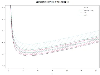
Fig. 2 depicts the operation of controller in the safe region with 3 cases. Lined areas contain Recognition and response time. Recognition and response time severely affect the recovery time headway range. Each function’s safe region is quite different due to the recognition and response time. With three CAV’s states, ACC is the best stable states because of the high accuracy of sensor fusion proved by ASIL. CACC stability states is more unstable than ACC stability states due to a processing time and the instability of the radio communication technology like WAVE(IEEE 802.11p) affected by radio interruption. On the other hand, recovery time period of ACC is longer than that of CACC because malfunction damage of ACC is higher than that of CACC.
Figure 2: Operation of controller in the safe region.
5.
CONCLUSION
We propose a minimum time headway range using affected by long response time and amplitude of the perturbation. The benefits of this experiment are twofold. First, applying stability of new technologies to car following model will be available, which needs to secure road safety of new technologies. Also, relationship between response time and the recovery time headway range will be the standards of the introduction of the new and safe technologies of CAVs.
REFERENCES
AASHTO, A. (2001). Policy on geometric design of highways and streets. American Association of State Highway and Transportation Officials, Washington, DC, 1(990), 158.
Althoff, M., & Mergel, A. (2011). Comparison of Markov chain abstraction and Monte Carlo simulation for the safety assessment of autonomous cars. IEEE Transactions on Intelligent Transportation Systems, 12(4), 1237-1247.
Anderson, J. M., Nidhi, K., Stanley, K. D., Sorensen, P., Samaras, C., & Oluwatola, O. A. (2014). Autonomous vehicle technology: A guide for policymakers. Rand Corporation.
Badhrudeen, M., Ramesh, V., & Vanajakshi, L. (2016). Headway Analysis using Automated Sensor Data under Indian Traffic Conditions. Transportation Research Procedia, 17, 331-339.
Jia, D., & Ngoduy, D. (2016). Enhanced cooperative car-following traffic model with the combination of V2V and V2I communication. Transportation Research Part B: Methodological, 90, 172-191. Jin, I. G., & Orosz, G. (2014). Dynamics of connected vehicle systems with delayed acceleration feedback. Transportation Research Part C: Emerging Technologies, 46, 46-64.
Kaempchen, N., Schiele, B., & Dietmayer, K. (2009). Situation assessment of an autonomous emergency brake for arbitrary vehicle-to-vehicle collision scenarios. IEEE Transactions on Intelligent Transportation Systems, 10(4), 678-687.
Litman, T. (2014). Autonomous vehicle implementation predictions. Victoria Transport Policy Institute, 28.
C.J. Messer et al. Traffic flow theory – A monograph, Transportation Research Board special report 165, 1997.
Milanés, V., & Shladover, S. E. (2014). Modeling cooperative and autonomous adaptive cruise control dynamic responses using experimental data. Transportation Research Part C: Emerging Technologies, 48, 285-300.
National Instruments (2012). National Instruments White Paper on ISO 26262 functional safety standard . http://www.ni.com/white-paper/13647/en/#toc2.
Pueboobpaphan, R., Park, D., Kim, Y., & Choo, S. (2013). Time headway distribution of probe vehicles on single and multiple lane highways. KSCE Journal of Civil Engineering, 17(4), 824-836.
SAE international (2014). Automated driving – SAE International. https://www.sae.org/misc/pdfs/automated_driving.pdf
Svensson, L., & Eriksson, J. (2015). Tuning for ride quality in autonomous vehicle: Application to linear quadratic path planning algorithm.
Treiber, M., & Kesting, A. (2013). Traffic flow dynamics. Traffic Flow Dynamics: Data, Models and Simulation, Springer-Verlag Berlin Heidelberg.
Treiber, M., & Kesting, A., (2017). The Intelligent Driver Model with Stochasticity-New Insights Into Traffic Flow Oscillations. Transportation Research Procedia, 23, 174-187.
Vanholme, B., Gruyer, D., Lusetti, B., Glaser, S., & Mammar, S. (2013). Highly automated driving on highways based on legal safety. IEEE Transactions on Intelligent Transportation Systems, 14(1), 333-347.
Weiß, C. (2011). V2X communication in Europe–From research projects towards standardization and field testing of vehicle communication technology. Computer Networks, 55(14), 3103-3119.