IN
DEGREE PROJECT MEDICAL ENGINEERING, SECOND CYCLE, 30 CREDITS
,
STOCKHOLM SWEDEN 2016
Real life analysis of myoelectric
pattern recognition using
continuous monitoring
JOHAN AHLBERG
KTH ROYAL INSTITUTE OF TECHNOLOGY SCHOOL OF TECHNOLOGY AND HEALTH
Abstract
The use of non-invasive signal acquisition methods is today the standard for testing pattern recog-nition algorithms in prosthetic control. Such research had shown consecutively high performance on both prerecorded and real time data, yet when tested in real life they deteriorate.
To investigate why, the author who is a congenital amputee, wore a prosthetic system utilizing pattern recognition control on a daily basis for a five-day period. The system generated one new classification every 50 ms and movement execution was made continuously; for classifying open/close; and by winning a majority vote; for classifying side grip, fine grip and pointer. System data was continuously collected and errors were registered through both a manual and an automatic log system. Calculations on extracted data show that grip classifications had an individual accuracy of 47%-70% while open/close got 95%/98%, but if classified according to a majority vote, grips increased their accuracy to above 90% while open/close dropped to 80%. The conclusion was that majority vote might help complex classifications, like fine grips, while simpler proportional movements is exacerbated by majority voting. Major error sources were identified as signal similarities, electrode displacements and socket design.
After the daily monitoring ended the systems functionality was tested using the "Assessment of Capacity for Myoelectric Control". The ACMC results showed that the system has similar func-tionality to commercial threshold control and thus is a possible viable option for both acquired and congenital amputees.
Sammanfattning
Användningen av icke-invasiva signalavläsningsmetoder är för nuvarande standarden inom utvärderingar av mönsterigenkännings-algoritmer för proteskontroll. Forskning inom området har konsekvent visat på hög prestanda för både ansamlat och realtids data, men när algoritmerna testas i verkliga livet fungerar de ej väl.
För att undersöka varför har författaren, som har en kongenital amputation, burit en protes vilken använder mönsterigenkänningskontroll i sitt vardagliga liv under en femdagars period. Systemet genererade en ny klassificering var 50 ms och rörelse-utförande skedde antingen kontinuerligt; för öppna/stäng; eller genom att vinna en majoritetsröstning, för att klassificera greppen sidogrepp, fingrepp samt peka. Data insamlades kontinuerligt och felklassificeringar registrerades genom både ett manuellt och ett automatiskt markeringssystem.
Beräkningar på insamlade data visade att för grepp låg den individuella träffsäkerheten på 47%-70% medan öppna/stäng var 95%/98%, men om data grupperades ökade träffsäkerheten för greppen till 90% medan för öppna/stäng minskade den till 80%. Slutsatsen blev då att majoritetsröstning hjälper mer komplexa rörelser som grepp, men är hindrande för mer väldefinierade proportionella öppna/stäng rörelser. De största felkällorna identifierades som likheter i signaler, elektrodavbryt-ningar och design av proteshylsan.
Efter slutförd daglig övervakning undersöktes funktionaliteten hos systemet med hjälp av funk-tionalitetstestet "Assessment of Capacity for Myoelectric Control". ACMC testen visade att systemet hade liknande funktionalitet som kommersiell tröskelkontrol och därmed kan ses som ett möjligt al-ternativ för kontroll, både hos dem med förvärvade och kongenitala amputationer.
Acknowledgements
I want to thank my father and my partner for their emotional support. Without them I would have perished.
I want to thank my supervisors Enzo Mastinu and Max Ortiz for their unwavering guidance and advice throughout this project.
I want to thank Jason Millenaar and Stewe Jönsson for their help in building the 3D printed parts and the socket respectively. Without them the project would have been nothing but dreams held up by duct tape.
I want to thank Sonam Iqbal and Alejandra Zepeda for their help with soldering, building the elec-trodes and subsequently proofreading my master thesis.
Lastly but not least, I want to thank the occupational therapists Anita Stockselius and Liselotte Hermansson for their help in performing the functionality tests and the subsequent analysis of it.
Contents
List of Figures List of Tables 1 Introduction 1 1.1 Background . . . 1 1.2 Objective . . . 2 2 Method 3 2.1 Virtual training and validation . . . 32.1.1 Electrode placement and optimal electrodes/movements set . . . 3
2.1.2 Investigation of optimal set for final setup . . . 4
2.2 System implementation . . . 5
2.2.1 Inner Socket . . . 5
2.2.2 Control system and circuit . . . 6
2.2.3 Prosthetic hand and Movement execution . . . 7
2.2.4 Continuous logging . . . 7
2.2.5 Error logging . . . 8
2.3 Functionality measurements . . . 9
2.3.1 Monitoring tests . . . 9
2.3.2 Information identification and data structuring . . . 9
2.3.3 Functionality tests . . . 10
3 Results 11 3.1 Virtual training . . . 11
3.1.1 Electrode placements . . . 11
3.1.2 Optimal movement and electrode sets . . . 11
3.2 Accuracy measurements and error identification . . . 15
3.3 Functional evaluation tests . . . 18
4 Discussion 19 4.1 Electrode placement and movement sets . . . 19
4.2 Accuracy . . . 19
4.2.1 Error logging methods . . . 19
4.2.2 Data structuring . . . 20
4.3 Error identification . . . 20
4.3.2 Electrode displacements . . . 21
4.4 Observed and perceived functionality . . . 22
4.5 Limitations . . . 23
4.5.1 Virtual tests . . . 23
4.5.2 Continuous monitoring and log methods . . . 23
4.5.3 Data structuring . . . 24
4.5.4 Functionality . . . 24
5 Conclusion 25
Bibliography 27
A Literature study A1
A.1 Commercial systems . . . A1 A.2 State of the art control systems . . . A1 A.2.1 Pattern recognition . . . A2 A.2.2 Implantable electrodes . . . A3 A.2.3 Targeted Muscle Reinnervation . . . A4 A.2.4 Brain Computer Interfaces . . . A4 A.2.5 Limitations . . . A5 A.2.6 BioPatRec and the Artificial Limb Controller . . . A6 A.3 Classification robustness . . . A7 A.4 Congenital amputees and advanced control . . . A8 A.5 Methods of functional evaluation . . . A9 Bibliography, Literature study A11 B Protocol Virtual training v1 B1 C Protocol Virtual training v2 C1 D Protocol Electrode manufacturing D1 E Protocol Monitoring tests E1 F Protocol Functionality tests F1
List of Figures
2.1 Movement types . . . 4
2.2 Pattern recognition system . . . 5
2.3 Inner socket . . . 5
2.5 Grip translation . . . 7
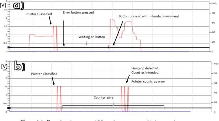
2.6 Error logging . . . 8
3.1 Electrode placement . . . 11
3.2 Virtual tests, Round 1, Online accuracy . . . 13
3.3 Virtual tests, Round 1, Motion completion times . . . 13
3.4 Virtual tests, Round 1, Motion completion rates . . . 13
3.5 Virtual tests, Round 2, Online accuracy . . . 14
3.6 Virtual tests, Round 2, Motion completion times . . . 14
3.7 Virtual tests, Round 2, Motion completion rates . . . 15
3.8 Total amount of errors . . . 15
3.9 Confusion matrices, All movements . . . 17
3.10 Confusion matrices, Errors only . . . 18
4.1 Signal characteristics, Open/Pointer . . . 21
4.2 Signal characteristics, Close/Side Grip . . . 22 A.1 Modular Prosthetic Limb with 22 DOF . . . A1 A.2 Commercial prosthetics . . . A2 A.3 Pattern recognition flow chart . . . A3 A.4 Wireless implantable electrodes . . . A3 A.5 Osseointegrated human-machine gateway (OHMG) . . . A4 A.6 EEG setup . . . A4 A.7 Implantable brain computer interfaces . . . A5 A.8 BioPatRec flowchart . . . A6 A.9 Congenital amputees . . . A8 A.10 Functionality tests . . . A10 C.1 Electrode placement . . . C2 D.1 Electrode creation . . . D2
List of Tables
2.1 Movement sets . . . 4
2.2 Schedule, Examination round 1 . . . 4
2.3 Schedule, Examination round 2 . . . 4
3.1 Virtual tests, Round 1, Online accuracy . . . 12
3.2 Virtual tests, Round 1, Motion completion time . . . 12
3.3 Virtual tests, Round 1, Motion completion rates . . . 12
3.4 Virtual tests, Round 2, Online accuracy . . . 14
3.5 Virtual tests, Round 2, Motion completion times . . . 14
3.6 Virtual tests, Round 2, Motion completion rates . . . 15
3.7 Accuracy of recorded data, Automatic error identification, Grouped . . . 16
3.8 Accuracy of recorded data, Manual error identification, Grouped . . . 16
3.9 Accuracy of recorded data, Automatic error identification, Individual . . . 16
3.10 Accuracy of recorded data, Manual error identification, Individual . . . 16
3.11 Intra classification accuracies . . . 17
Chapter 1
Introduction
1.1
Background
Prosthetics are one of the oldest forms of rehabilitative therapies in history. Thanks to the tech-nological developments in preceding decades several great advances in prosthetics have occurred. In robotics it is now possible to produce artificial limbs with joint articulation and degrees of movement that rival the human counterpart[1]. However, this technology is currently not used in commer-cial markets due to a lack of adequate control, with only commercommer-cial threshold1 control currently available[2].
To address this, research has focused on another method known as pattern recognition (PR) [3]. By extracting relevant information from a set of data, it works by looking at the signal structures rather than each source individually. Pattern recognition can work with any type of signal acquisition method, both invasive and noninvasive. As evident by research done in the field [4, 5, 6, 7], invasive signal acquisition methods produce higher accuracy and is a viable option for better functionality. Problem is that several large patient groups are excluded from invasive methods2. Reasons include associated risks, not meeting inclusion criteria’s and cost. Thus a viable and noninvasive option, such as surface electrodes, is needed.
In research overall, surface electrodes are more common than invasive methods. Tests on collected data (offline) and real time data (online) show a high level of accuracy and overall functionality[3, 4]. Yet, when tested by patients in real world settings these results differ[8].
A disconnection seems to exist between laboratory results and those experienced by patients outside the clinical environment. Reasons can be linked to different sources including motion artifacts, electrode displacements, electromagnetic interference etc [9]. However, which factors and error types that play crucial roles is still undetermined. Few tests have investigated long term effects of the pattern recognition control and no long term continuous monitoring has been done. This makes it difficult to identify and mitigate error causing effects on the system, hindering commercial application. Consequently, an investigation and analysis was performed by the author in this thesis. It was conducted in conjuncture with the Biomedical signals and systems group at Chalmers University of Technology and the biomedical engineering company Integrum.
1Threshold control: Open/close is mapped to proportional activation of one or two electrodes 2In depth analysis is found in Appendix A, Literature study, A.2.5
1.2
Objective
The main objective was to investigate the functionality of a pattern recognition system for control-ling a prosthetic in a real life environment. This was obtained by wearing the system and continuously logging errors as they emerged. To achieve this, the objective was broken down to the following tasks:
• Investigate functional viability in virtual tests
• Build a functional prosthetic system that can operate a commercial prosthetic hand using both pattern recognition control and threshold control
• Generate a method for logging errors continuously in everyday life
• Wear the system and continuously collect data from a real life environment to quantify system performance and identify error origins
Chapter 2
Method
2.1
Virtual training and validation
Before creating the system, it was of importance to determine if the tester, i.e. the author, can produce the necessary signals required for the pattern recognition system. As previously argued1, the viability of pattern recognition in congenital amputees is controversial. And if possible, the optimal electrode placement and electrode/movement configurations were also needed.
2.1.1
Electrode placement and optimal electrodes/movements set
Optimal electrode positioning was determined by using high density EMG. Different types of electrode/ movement combinations were then examined during six days of testing. Each test was comprised of three recording session for movement familiarity and one motion test for functional evaluation2. A recording session consisted, per movement, of three contractions and three rest periods,
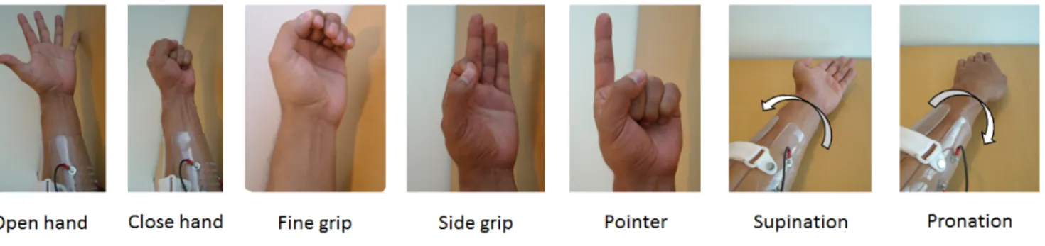
three seconds each. Last recording session was used to train the classifier for the motion test. The motion tests utilized a linear discriminant analysis (LDA) algorithm with a single classifier topology for classification. Each test was with two trials of three repetitions per movement for three seconds. Features selected were mean absolute value (mabs), slope changes (slpch2), zero crossings (zc) and waveform length (wl). Control algorithm and features were chosen given previous high performance in BioPatRec [10]. Movements selected are commonly found in multiple grip prosthetics and were divided in two sets (Figure 2.1 and Table 2.1). Both sets also implicitly include rest. Electrodes were positioned in sets of either six or eight pairs.
1Appendix A, Literature study, A.4
Figure 2.1: Movement types
5 Movement set Open hand Close hand Side grip Fine Grip Pointer
7 Movement set Open hand Close hand Side grip Fine Grip Pointer Supination Pronation Table 2.1: Movement sets
Movement/electrode sets were tested according to Table 2.2. These tests were exploratory and did not generate enough statistical significance for a final decision. They served as a guide for further analysis of the two best performing movement/electrode sets found in the previous test.
Day 1 Day 2 Day 3 Day 4 Day 5 Day 6 Morning - 7 movements 8 channels 5 movements 8 channels 7 movements 8 channels 7 movements 8 channels -Afternoon 7 movements 8 channels 7 movements 8 channels -7 movements 6 channels 5 movements 6 channels 5 movements 6 channels Table 2.2: Schedule, Examination round one
2.1.2
Investigation of optimal set for final setup
New examinations using the two best performing movement/electrode sets were done, each sepa-rated by six weeks to mitigate any learning effect. Tests were performed with the same test settings as previous examinations. The test followed the schedule in Table 2.3. Data collected was used to determine the final electrode/movement set.
Day 1 Day 2 Day 3 Day 4 Day 5 Morning 5 movements 6 channels 7 movements 8 channels 5 movements 6 channels 7 movements 8 channels 5 movements 6 channels Afternoon 7 movements 8 channels 5 movements 6 channels 7 movements 8 channels 5 movements 6 channels 7 movements 8 channels Table 2.3: Schedule, Examination round 2
2.2
System implementation
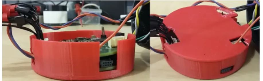
Moving from a virtual environment to the real world requires a physical system. In this thesis it revolves primarily around a retrofitted pattern recognition control system known as the Artificial Limb Controller (ALC) built by Mastinu et al.[11]. Its implemented on two custom printed circuit boards as seen in figure 2.3 3. The top board is the main board, containing the components enabling
the pattern recognition control. It houses the ADS1299 used for signal acquisition, and a ARM 4 based MCU, functioning as the main processing unit. Connected to this is the expansion board, housing system interfaces for information storage and transmission. This includes an SD card for storage, pulse width modulation (PWM) circuit for pulse generation and an UART connection for computer communication. To this new functions and components were created or old ones remade to ensure system functionality. The following chapter shows how these were created and added to the original system.
Figure 2.2: Pattern recognition system in shock protection box
2.2.1
Inner Socket
The inner socket functions as the interface between the user and the system. It houses six pairs of electrodes for the signal acquisition together with a reference electrode. Each electrode was custom made as described in appendix D.
Figure 2.3: Inner socket.
a) Inner socket b) Electrode c) Electrode attached to socket d) Inner view of the socket viewing electrodes
2.2.2
Control system and circuit
Classification
Created with the ALC is an extensive software library, enabling it to perform actions such as signal acquisition, treatment, feature extraction and signal classification. Signal acquisition was set at a sampling frequency of 1000 Hz with a classification performed every 50 ms. The feature extraction for movement prediction used the last 100 ms. Algorithm for classification was LDA and the features were the four previously selected (mabs, slpch2, tzc and wl).
Pattern recognition systems are in general structured so that each classification causes an incre-mental movement towards an end state. With the exception of open and close, this is not how a modern multi DOF prosthetic hand functions. Instead, each grip is represented by a finite state and if the hand recognizes a state command, the movement is executed until reaching end position. Thus, a new classification strategy was needed.
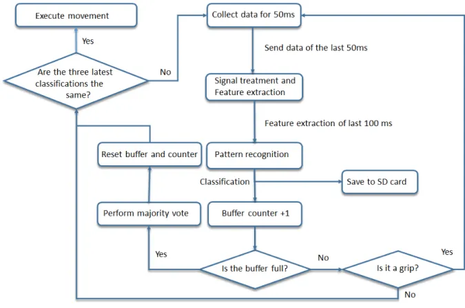
Figure 2.4: Classification algorithm
This new strategy is a buffer system that employs a majority vote for grip execution (Figure 2.4). In order to win, the majority of the classifications in the buffer must be the intended grip. Without this strategy, transitory events would render the system unusable. A continuity filter was also implemented for all movements, requiring the three latest classifications to be equal to the intended movement for execution. This is also to mitigate transitory events.
For comparative analysis a secondary threshold control also was implemented. This was later used in the functionality tests.
2.2.3
Prosthetic hand and Movement execution
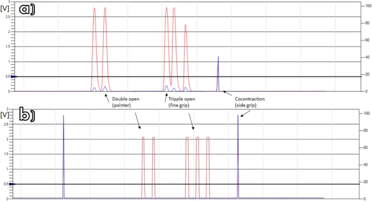
After final classification the output is sent to the hand. Open and close are controlled by the proportional level of activation, but for grip selection modern multi DOF prosthetics utilize temporal patterns. The prosthetic, an Ilimb ultra, employs four types of temporal patterns achieved by doing hold open, co-contraction4, a double open impulse or a triple open impulse. Selected grip patterns
that these encode is open palm5, side grip, fine grip and pointer respectively.
Using the knowledge of these control patterns, a translational protocol is created that mimic these for grip execution. This is visualized in figure 2.5.
Figure 2.5: Original and treated signal. a) Standard threshold control
b) Translation of a classified grip as sent by the system.
2.2.4
Continuous logging
To save important system parameters and classification characteristics, a continuous save function was implemented. It saves the system data such as the block index, output index, error markers, grip counters for classified grips and all features for the six channels. Due to the amount of saved data and the resulting data rate, it was decided that only movements were saved and to keep count of ’rest’ classifications a counter was used.
4Co-contraction: Activation of both electrode at the same time
2.2.5
Error logging
Two error logging functions were developed; one manual and one automatic.
In the manual function, the error markers are placed using a push-button array. Five buttons were placed on the outer socket, representing each individual movement. Pressing an error button causes a system interrupt making the system wait for a push to indicate the intended movement. It then marks that an error has occurred and what the intended movement was. While accurate, this method is heavily user dependent. Thus a secondary automatic method was developed.
For the automatic function the identifier operates only on grips and measuring time differences be-tween them. After a grip has been executed a counter start. If a new grip is executed within a predetermined time period, it assumes that the first was not intended and the second one correct. It then marks that an error has occurred. Counter value was set to five seconds; long enough not to be masked by execution speed yet short enough not to count correct movement changes.
2.3
Functionality measurements
2.3.1
Monitoring tests
When the system was deemed operational the continuous monitoring test began. It was structured to capture data continuously during a five day period. For each day the system was retrained before usage. More detailed account of the monitoring schedule can be found in appendix E.
2.3.2
Information identification and data structuring
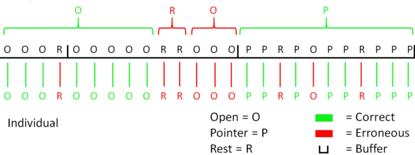
After the continuous monitoring was completed the data was extracted for further analysis. Error origins were investigated by looking at the data four seconds prior to the set marker. Grips were given the highest priority since they produce the greatest error. Granted the discovery of multiple grips the latest was considered. If no grip was found, then the most prominent movement within four seconds was deemed the source of error.
The data was sectioned into two categories, groups and individual, to calculate representative accuracies of continuous and majority vote movements. For group accuracy, the continuous movements were categorized in activation groups, i.e. series of similar classifications. A correct classification series was defined as one that could win a majority vote. The individual accuracy was calculated counting each of the classification by themselves. For grips, this entailed that each element in a grouping was counted individually. A visualization of the structuring is shown in Figure 2.7.
2.3.3
Functionality tests
Functionality tests were employed for comparative analysis and objective evaluation of the system. Previous investigations6 revealed two adequate methods, the Assessment of Capacity for Myoelectric Control (ACMC) and the Activities Measure for Upper Limb Amputees (AM-ULA). Given extensive tests, high validity and easy accessibility, the ACMC was deemed most appropriate.
The functionality tests were conducted during one full day of testing. Each test consisted of three functional tasks
• Building a ready to assemble project (A lamp). • Wrapping a present and writing a gift card. • Setting up a table for six persons.
An occupational therapist organized the tests, giving instructions while recording. Evaluation and review was done by a second occupational therapist without knowledge of what control method was being used in each recording.
More detailed account of the testing can be found in appendix F.
Chapter 3
Results
3.1
Virtual training
3.1.1
Electrode placements
Results from the high density EMG recordings show optimal placement of electrodes as seen in Figure 3.1. Electrode placement of electrodes 1-6 overlap for both sets. Reference is placed on elbow.
(a) Electrode placement, residual limb, right side
(b) Electrode placement, residual limb, left side
Figure 3.1: Electrode placement. 6 channel setup: 1-6; 8 channel setup: 1-8
3.1.2
Optimal movement and electrode sets
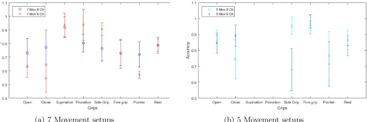
EMG measurements were recorded using the schedule found in Table 2.2. The online accuracy of the completed movements, completion time and completion rate are presented in Tables 3.1-3.3 and Figures 3.3-3.5 respectively. Accuracies and rates are scaled from 0 to 1.
Accuracy /Movement 7 Movements 8 Channels 5 Movements 8 Channels 7 Movements 6 Channels 5 Movements 6 Channels Open hand 0.73±0.11 0.90±0.03 0.64±0.09 0.85±0.06 Close hand 0.77±0.13 0.74±0.12 0.55±0.10 0.89±0.06 Pronation 0.92±0.08 NA 0.94±0.08 NA Supination 0.80±0.07 NA 0.94±0.11 NA Side grip 0.77±0.09 0.96±0.06 0.90±0.05 0.68±0.13 Fine grip 0.74±0.09 0.96±0.06 0.72±0.11 0.98±0.04 Pointer 0.72±0.09 0.77±0.15 0.57±0.02 0.72±0.14 Rest 0.79±0.05 0.87±0.06 0.79±0.06 0.83±0.06
Table 3.1: Online accuracy of completed movements
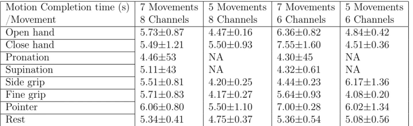
Motion Completion time (s) /Movement 7 Movements 8 Channels 5 Movements 8 Channels 7 Movements 6 Channels 5 Movements 6 Channels Open hand 5.73±0.87 4.47±0.16 6.36±0.82 4.84±0.42 Close hand 5.49±1.21 5.50±0.93 7.55±1.60 4.51±0.36 Pronation 4.46±53 NA 4.30±45 NA Supination 5.11±43 NA 4.32±0.61 NA Side grip 5.51±0.81 4.20±0.25 4.44±0.23 6.17±1.36 Fine grip 5.71±0.83 4.17±0.27 5.64±0.93 4.08±0.20 Pointer 6.06±0.80 5.50±1.10 7.00±0.28 6.02±1.34 Rest 5.34±0.41 4.75±0.37 5.36±0.54 5.08±0.56
Table 3.2: Motion completion time
Motion Completion rate /Movement 7 Movements 8 Channels 5 Movements 8 Channels 7 Movements 6 Channels 5 Movements 6 Channels Open hand 0.97 1.00 0.83 1.00 Close hand 0.90 1.00 0.67 1.00 Pronation 0.97 NA 1.00 NA Supination 0.43 NA 0.83 NA Side grip 1.00 1.00 1.00 0.83 Fine grip 0.90 1.00 1.00 1.00 Pointer 0.77 1.00 0.33 1.00 Rest 0.85 1.00 0.81 0.97
(a) 7 Movement setups (b) 5 Movement setups
Figure 3.2: Online accuracy of the completed movements
(a) 7 Movement setups (b) 5 Movement setups
Figure 3.3: Motion completion times
(a) 7 Movement setups (b) 5 Movement setups
From these results it was extrapolated that, of the four movement sets, the two most promising ones were the six electrodes/five movements and the eight electrodes/seven movements. Thus these were investigated further.
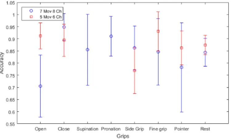
Schedule in Table 2.3 was used when comparing the two most promising sets to find the most functional. The online accuracy of the completed movements, completion time and completion rate recorded from these tests are presented in Tables 3.4-3.6 and Figures 3.5-3.7 respectively. Accuracies and rates are scaled from 0 to 1.
Accuracy /Movement 7 Movements 8 Channels 5 Movements 6 Channels Open hand 0.71±0.13 0.91±0.05 Close hand 0.95±0.06 0.90±0.07 Pronation 0.86±0.15 NA Supination 0.91±0.08 NA Side grip 0.86±0.09 0.77±0.10 Fine grip 0.85±0.14 0.93±0.08 Pointer 0.78±0.18 0.86±0.07 Rest 0.84±0.06 0.88±0.04 Table 3.4: Online accuracy values
Figure 3.5: Online accuracy graph
Motion Completion time (s) /Movement 7 Movements 8 Channels 5 Movements 6 Channels Open hand 5.94±1.14 4.43±0.28 Close hand 4.24±0.26 4.52±0.37 Pronation 4.94±1.12 NA Supination 4.46±0.44 NA Side grip 4.71±0.55 5.51±0.78 Fine grip 4.89±0.87 4.34±0.42 Pointer 5.54±0.16 4.78±0.47 Rest 4.96±0.46 4.71±0.27
Table 3.5: Motion completion time, values
Motion Completion Rate /Movement 7 Movements 8 Channels 5 Movements 6 Channels Open hand 0.90 1.00 Close hand 1.00 1.00 Pronation 0.97 NA Supination 0.70 NA Side grip 0.97 1.00 Fine grip 0.90 1.00 Pointer 0.93 0.97 Rest 0.91 0.99
Table 3.6: Motion Completion Rate, values
Figure 3.7: Motion Completion Rate, graph These results showed that the five movements/six electrode setup was preferable given better online accuracy, completion times and rates for most movements. Hence this electrode/movement setup was chosen to be six electrodes for classifying the five movements open, close, side grip, fine grip and pointer.
3.2
Accuracy measurements and error identification
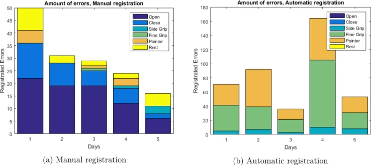
Total recording duration was five days with a mean time of eight hours/day. Total amount of errors per day (Figure 3.8) depended on the overall activity.
(a) Manual registration (b) Automatic registration
Figure 3.8: Total amount of errors
Calculated mean accuracies and general real life accuracy means are presented in table 3.7-3.11. Accuracies are scaled from 0 to 1.
Accuracy
Open
Close
Side Grip
Fine Grip
Pointer
Rest
Day 1
0.85
0.89
0.95
0.83
0.84
1.00
Day 2
0.78
0.86
0.98
0.86
0.63
1.00
Day 3
0.77
0.85
1.00
0.83
0.79
1.00
Day 4
0.81
0.73
0.82
0.95
0.79
1.00
Day 5
0.73
0.78
0.92
0.91
0.74
1.00
Mean
0.79±0.05
0.82±0.07
0.93±0.07
0.85±0.03
0.76±0.08
1.00±0.00
Table 3.7: Accuracy of recorded data, Automatic error identification, Grouped
Accuracy
Open
Close
Side Grip
Fine Grip
Pointer
Rest
Day 1
0.84
0.90
0.93
0.95
0.92
1.00
Day 2
0.79
0.86
0.96
0.97
0.91
1.00
Day 3
0.77
0.85
0.91
0.95
0.84
1.00
Day 4
0.81
0.73
0.97
0.98
0.97
1.00
Day 5
0.72
0.78
0.98
0.98
0.96
1.00
Mean
0.79±0.04
0.82±0.07
0.95±0.03
0.97±0.02
0.92±0.05
1.00±0.00
Table 3.8: Accuracy of recorded data, Manual error identification, Grouped
Accuracy
Open
Close
Side Grip
Fine Grip
Pointer
Rest
Day 1
0.97
0.99
0.81
0.57
0.71
1.00
Day 2
0.96
0.99
0.77
0.39
0.55
1.00
Day 3
0.95
0.99
0.72
0.44
0.62
1.00
Day 4
0.95
0.97
0.63
0.56
0.72
1.00
Day 5
0.96
0.98
0.70
0.45
0.76
1.00
Mean
0.96±0.01
0.98±0.01
0.72±0.07
0.48±0.08
0.67±0.09
1.00±0.00
Table 3.9: Accuracy of recorded data, Automatic error identification, Individual
Mean Accuracy
Open
Close
Side Grip
Fine Grip
Pointer
Rest
Day 1
0.95
0.98
0.67
0.53
0.68
0.99
Day 2
0.97
0.99
0.67
0.36
0.50
1.00
Day 3
0.95
0.98
0.60
0.42
0.50
1.00
Day 4
0.96
0.97
0.63
0.54
0.70
0.95
Day 5
0.97
0.98
0.66
0.44
0.75
1.00
Mean
0.96±0.01
0.98±0.01
0.64±0.03
0.46±0.08
0.63±0.12
0.99±0.02
By investigating the source of each registered error the following confusion matrices were created
Figure 3.9: Confusion matrices, all movements
1: Open, 2: Close 3: Side grip, 4: Fine grip, 5: Pointer, 6: Rest
Given how the correctly classified movements outweigh the identified errors, previous confusion matrices do not give a representative view of how the errors spread across the movements. Therefore, confusion matrix 3.10 was calculated by viewing error distributions across all movements, showing relative frequency.
Because of differences found between individual and grouped accuracies the winning rate of each correct classification was measured. Results are presented in Table 3.11. The general means standard deviation was calculated using analysis of variance (ANOVA).
Side grip Fine Grip Pointer Day 1 0.65±0.26 0.66±0.25 0.64±0.23 Day 2 0.65±0.27 0.57±0.24 0.74±0.22 Day 3 0.64±0.24 0.57±0.25 0.67±0.25 Day 4 0.72±0.23 0.62±0.23 0.67±0.20 Day 5 0.72±0.26 0.56±0.26 0.67±0.25 General mean 0.68±0.26 0.60±0.24 0.68±0.23
Figure 3.10: Confusion matrices, Errors only
1: Open, 2: Close 3: Side grip, 4: Fine grip, 5: Pointer, 6: Rest
3.3
Functional evaluation tests
Results provided the occupational therapist was the following:
Activity Pattern recognition Threshold control Build a lamp 62.0 74.3
Wrapping a present 66.4 74.3 Setting up a table for six persons 66.4 64.1
Table 3.12: ACMC score. Minimal detectable change in the same assessor is 2.5 units
Comments from the occupational therapist was that in threshold control the prosthetic was used in more positions with better timing in both opening and closing. The prosthetic was also not observed as much in threshold control during usage in comparison to pattern recognition control.
Chapter 4
Discussion
4.1
Electrode placement and movement sets
The first round of virtual tests results shows that more electrodes generally lead to higher accura-cies. However, this might not equate to better real life performance. A single electrode malfunction could decrease accuracy by ˜10% [12] and more electrodes could increase this risk. Since the two differentiating electrodes, number seven and eight, are positioned in spots with high residual limb movements it could result in more electrode shifts. Hence, the added benefits of eight electrodes ought to outweigh the risks. Such benefits exist for seven movements through added wrist rotation but no extra added benefit is found for only the five movements. Thus the setup choices for secondary testing rounds became the six electrode/five movement and the eight electrode/seven movement ones. In the second round of tests, its clear that the five movement/six electrode setup gave better accu-racies, completion times and completion rates for most movements. Most importantly, it gave higher scores for the two continuous open/close movements. Since these are not covered by the majority vote buffer their accuracy and functionality carried higher priority. Thus the five movement/six electrode setup was chosen.
4.2
Accuracy
By reviewing the performances of each day it can be seen that they keep a relatively stable accuracy level (std< 12%) with few exceptions. Results show deviation within log-methods and data structuring, warranting further analysis.
4.2.1
Error logging methods
A quick view of Figure 3.9 can lead one to believe that manual and automatic methods produce similar results. However, when reviewing the registered error distribution in figure 3.8 together with the confusion matrix 3.10 it is revealed that the results differ. The automatic method identifies multiple amounts of what the manual method does, yet encompass less movements. Furthermore the confusion matrix in Figure 3.10 reveals that most errors originate from within the class itself. Reasons why can depend on classification overshoots or on the temporal filter in the Ilimb that only allows a fully opened hand to execute grips. While there exists some overlap with the manual method, there is no way of telling if the error is true or not. A better measurement of the accuracy is the manual
error logger. While it might miss errors in a series, its more accurate in portraying the abstract performance. It is thus used for further analysis.
4.2.2
Data structuring
Independent of error logging method, the accuracies follow a similar pattern when reviewed in grouped versus individual classifications, as presented by Table 3.7-3.10 and Figure 3.9. For contin-uous movements, the accuracy is around 80% in grouped classifications (Table 3.8) but when viewed individually, the accuracies go up to 95-98% (Figure 3.10). Grips, however, follow an inverse trend. Mean accuracies are above 90% when calculated in groups (Figure 3.8), yet according to individ-ual classification these accuracies drop to 71%, 47% and 64% for side grip, fine grip and pointer respectively (Table 3.10).
What can be concluded from these results is that if the continuous open/close movements were grouped similar to that of a majority vote, it resulted in worse accuracy than if classified individu-ally. Underlying reason for this could be that these movements often require quick and fast changes necessary for finer motor control. A majority vote system would impede function given that most commands are composed of smaller groupings instead of longer classification series. For grips the results are reversed with individual classifications giving worse results. This points to the fact that while the intended movement does win the majority vote it is not with a large majority, something supported by intra classification accuracies (Table 3.11). Hypothesis for this is that, while the con-tinuous movements are composed of strong and localized muscle groups, the grips also incorporate smaller muscles to build a more complex pattern. Maybe because of this added complexity, it is difficult to produce a stable signal and thus they are benefited from a majority vote system. The low individual classification accuracy might explain why incremental pattern recognition systems fail in real life settings.
4.3
Error identification
From confusion matrix 3.10, it can be seen that the error distribution has a large spread across all movements with some clusters being more prominent. While they all would be of interest for further analysis, using different sorting algorithms such as selforganizing map and principle component analysis, the time scope of this thesis is unfortunately insufficient. Instead, a general analysis is provided in the following section on the most notable erroneous classifications and their presumed source.
4.3.1
Pattern similarities
The most prominent error was ‘Open’ being misclassified as a ‘Pointer’. Its prevalence was about 34% of all errors while the second largest error, ’Close’ being misclassified as ’Side grip’, only had a total prevalence of 14%. Both these errors were expected given that the movement pairs share many signal similarities.
Using Figure 4.1, the differences between ‘Open’ and ‘Pointer’ can be identified in channel five, an electrode with an large role in the close command. Reason why it differs can be theorized to depend on the fact that pointer does involve some closing motions, yet it would be difficult for the system to identify such small finer movements.
Figure 4.1: Signal characteristics, Open (left) and Pointer (Right)
For ‘Close’ and ‘Side grip’, differences can be seen in relative signal activation levels for channel four to six and overall signal strength (Figure 4.2). In channels three and four, an equal activation level for side grip is identified yet differ for close classifications.
What both these errors show is that the systems primary fault lies in differentiating movements with similar activation patterns. This arise ultimately from the surface electrodes noninvasive nature, resulting in reduced signal quality. Using different classification algorithms and feature combinations might provide more distinguishable data to work with, mitigating the erroneous effects. For this, more data on algorithm functionality in real life systems is imperative.
4.3.2
Electrode displacements
While signal similarities do contribute as an error source it is far from alone. While many external sources can be identified there is one serving as a unifier, namely the socket design itself. During the virtual tests the residual limb is treated as a static object and electrodes are not subjected to uneven or differentiating connectivity. The connection in a real prosthetic system cannot be seen as static given its interfacing with soft tissue. During a normal day the arm is subjected to varying amounts
Figure 4.2: Signal characteristics, Close (left) and Side grip (Right)
of load and shifting limb positions causing varying degrees of electrode contact. While not recorded as part of any protocol nor as a quantifiable unit, it was observed that a significant part of the errors occurred during motions or in odd positions. Further evidence was found during the first preliminary tests. Here, the electrode placed most distal to the elbow in pair number five was found not connecting unless in specific angles. This single electrode disconnection caused major classification errors making the system almost unusable. After refitting the electrode, the system returned to normal. Electrode displacements could be mitigated to some extent by varying positions during recording sessions.
4.4
Observed and perceived functionality
Accuracies provide a good measure of error prevalence but it fails to answer the broader question of functionality. Looking at the results given by the ACMC shows that threshold control has generally higher scores, except when setting a table. Better scores were attributed because of better timing with less discontinuations in movements. The prosthetic was also observed more greatly by the author when executing movements and the movement range was also more restricted when using pattern recognition. The difference can in part be explained by that threshold control was tested last
and thus tasks were more familiar. However, the scores are still high enough to deem the two systems "functional".
The test does identify an important difference between pattern recognition and threshold control. When using pattern recognition there existed a mistrust using the open and close command since they produced the highest frequency of errors. And while these errors where relatively few and far between they were frequent enough to warrant distrust. This resulted in the author limiting his range of motion to not lose electrode contact. More trust was put in threshold control given its simplic-ity of operations. For grips however the perceived functionalsimplic-ity between the methods was switched. Temporal grip selection usually feels forced causing a disconnect between user and the system. Using the grip selection provided by the pattern recognition however felt more intuitive and fast paced. A surprising result given that the author is a congenital amputee without any previous experience using his left hand. While the results are not statistically significant they do point to similar conclusions set by Kuiken [13], that pattern recognition could be a viable option for some congenital amputees. The results of the functionality tests and the perceived functionality takes into question if accu-racy; offline, online and/or using continuous monitoring; are representative of end user satisfaction. An example of this is the hot coffee problem: If a prosthetic drops a cup of hot coffee 1 every 100 times, could it be called trustworthy? In the end, it might be needed to use other quantities to model perceived functionality.
4.5
Limitations
4.5.1
Virtual tests
When conducting the first round of virtual test, the protocol was flawed. It was realized halfway through that six electrodes might be better in the end, resulting in a fundamental change of the schedule. This resulted in inadequate and inconclusive statistical significance. Because of this, the secondary round of tests was implemented on the two motion sets that showed the most promise, either in stability or in amount of movements.
4.5.2
Continuous monitoring and log methods
Originally the plan was to utilize raw data capturing to enable a more extensive signal analysis. Unfortunately, while the system could save raw data, this action generated transitory spikes in the movement executions. Reason for this was not identified in time and thus a continuous logging of only features was instead utilized. Time restraints kept the analysis from being more comprehensive given that the system only became functional close to the submission deadline. Data collection was also flawed given that the collected data had disconnections through erroneously saved data. This generated classification jumps for the grip counters. Since each save is incremental in nature these errors were mitigated by removing the difference between erroneous jumps.
4.5.3
Data structuring
Besides correct and erroneously identified data there exist unidentified groupings of grip classifica-tions. They are often large enough to win a majority vote yet fail to do so. Reason why the unfinished classifications occur could be as a result from classification overshoots or correct classifications falling between two buffers. Normally these would be classified as errors according to the worst case approach but this generated accuracies, grouped and individual, well below 50%. Such numbers would not give a fair representation of the system performance. Thus they are counted as correct in the accuracy measurements.
4.5.4
Functionality
As described previously the socket was one of the greatest issues with the system in terms of error generation. Moreover, it is also quite uncomfortable and given its tight fit gave a restricted range of motion. The socket itself was designed to put pressure to the epicondyles for stability but this generated a pressure against the ulnar nerve, resulting in numbness in the left lower side of the residual limb. Before further studies can be done this issue needs to be resolved. Future system should also not use a hard shell as the socket interface but focus on adding a soft lining inside the socket to reduce pressure effects on the residual limb.
Chapter 5
Conclusion
In the thesis it was demonstrated that the author could functionally operate a prosthetic sys-tem using pattern recognition control in everyday activities. By manual logging, it was shown that continuous movements utilizing larger muscle groups, such as open and close, have better accuracies when classified and executed individually while movements requiring finer muscular activations, such as grips, benefited from majority vote activation. Using this, >90% accuracy was achieved.
Analysis of the continuous data identified major error sources as signal similarities, electrode dis-placements and socket design. It was argued that mitigation of these might be achieved through different types of classification algorithms and feature combinations, differentiating positional train-ing and redesigntrain-ing the socket.
Functionality tests revealed slightly lower functional scores for pattern recognition to threshold con-trol, however still relatively high.
Ultimately this thesis shows that pattern recognition could be a viable alternative to threshold con-trol. Patient segments can include recently amputated or those that find standard control methods lacking.
Bibliography
[1] Matthew S Johannes, John D Bigelow, James M Burck, Stuart D Harshbarger, Matthew V Kozlowski, and Thomas Van Doren. An overview of the developmental process for the modular prosthetic limb. Johns Hopkins APL Technical Digest, 30(3):207–216, 2011.
[2] Claudio Castellini and Patrick Smagt. Surface emg in advanced hand prosthetics. Biological Cybernetics, 100(1):35–47, 2008.
[3] B. Peerdeman, D. Boere, H. Witteveen, R. H. in ’t Veld, H. Hermens, S. Stramigioli, H. Rietman, P. Veltink, and S. Misra. Myoelectric forearm prostheses: state of the art from a user-centered perspective. J Rehabil Res Dev, 48(6):719–737, 2011.
[4] Max Jair Ortiz-Catalan. Towards Natural Control of Artificial Limbs. Doktorsavhandlingar vid Chalmers tekniska högskola. Ny serie, no:. Institutionen för signaler och system, Medicinska signaler och system, Chalmers tekniska högskola„ 2014.
[5] T. A. Kuiken, G. Li, B. A. Lock, R. D. Lipschutz, L. A. Miller, K. A. Stubblefield, and K. B. En-glehart. Targeted muscle reinnervation for real-time myoelectric control of multifunction artificial arms. JAMA, 301(6):619–628, Feb 2009.
[6] J. E. Cheesborough, L. H. Smith, T. A. Kuiken, and G. A. Dumanian. Targeted muscle reinner-vation and advanced prosthetic arms. Semin Plast Surg, 29(1):62–72, Feb 2015.
[7] Mikhail A. Lebedev and Miguel A.L. Nicolelis. Brain machine interfaces: past, present and future. Trends in Neurosciences, 29(9):536 – 546, 2006.
[8] B.A. Lock. Design and Interactive Assessment of Continuous Multifunction Myoelectric Control Systems. Canadian theses. University of New Brunswick (Canada), 2005.
[9] Adaptive myoelectric pattern recognition toward improved multifunctional prosthesis control. Medical Engineering Physics, 37(4):424 – 430, 2015.
[10] M. Ortiz-Catalan, R. Branemark, and B. Hakansson. BioPatRec: A modular research platform for the control of artificial limbs based on pattern recognition algorithms. Source Code Biol Med, 8(1):11, 2013.
[11] Enzo Mastinu, Max Jair Ortiz-Catalan, and Bo Håkansson. Analog front-ends comparison: on the way to a portable, lowpower and low-cost emg controller based on pattern recognition. In Proceedings of the 37th Annual International Conference of the IEEE Engineering in Medicine and Biology Society. Milan, Aug 25-29, 2015, 2015.
[12] A. Stango, F. Negro, and D. Farina. Spatial correlation of high density emg signals provides features robust to electrode number and shift in pattern recognition for myocontrol. IEEE Transactions on Neural Systems and Rehabilitation Engineering, 23(2):189–198, March 2015. [13] M. Kryger, A. E. Schultz, and T. Kuiken. Pattern recognition control of multifunction myoelectric
prostheses by patients with congenital transradial limb defects: a preliminary study. Prosthet Orthot Int, 35(4):395–401, Dec 2011.
Appendix A
Literature study
A.1
Commercial systems
Given the advances in technological progress and component miniaturization, it is now technically possible to create a mechanical arm that has similar functionality to its biological counterpart [1].
Figure A.1: Mod-ular Prosthetic Limb with 22 DOF [1]
However, as evident by current commercial prosthetics, this is not currently being used by amputees. While there still are mechanical challenges left to solve, such as battery life and durability, these are not the main issues. What currently hinders prosthetics with multiple degrees of freedom is the issue of controllability [2]. Commercial prosthetic arms are either body powered prosthetics, operat-ing usoperat-ing a harness and cable system that is connected to a terminal device, or electrical prosthetic, controlled using one or two electrodes that read the user’s electromyography signals (EMG). EMG is a measurement of the electrical signals originating from contracting muscles. These signals are processed and translated into intended movement. Electrodes are placed on larger muscles, often with an-tagonistic relationships, in order to get clear signals. Older myoelectric prosthetic hands normally utilized this antagonistic relationship to map a "close" and "open" command to either electrode for comparison to a threshold level. This enables one degree of freedom (DOF) control [3] and is exemplified by Sensorhand from Ot-tobock. The most modern commercial myoelectric prosthetics are however more advanced, utilizing signal processing to differentiate different types of temporal patterns in order to switch between hand positions, giving more DOF. Commercial prosthetics here include the IlimbTM, BebionicTMand Michelangelo HandTM(Figure A.2).
A.2
State of the art control systems
The one or two site antagonistic EMG readings are useful in simpler command but lack complexity for more advanced control. Even if more electrodes at different activation sites were used it would work poorly [4, 5] since finding adequate control sites is difficult, making higher functionality impractical. To move around this, research has instead focused on the collective myoelectric pattern of activation to classify movements. This is the basis of myoelectric pattern recognition.
Figure A.2: From the left: A body powered device [?], Sensorhand from Ottobock, IlimbTMUltra from Touch bionics and BebionicTMfrom RSLSteeper
A.2.1
Pattern recognition
Pattern recognition is related to machine learning and has been used extensively in different applications, including speech recognition [6], hand writing recognition [7], military applications [8] and also applications related to the field of image analysis [9]. Its definition differs between different applications but can generally be described as a way to find and classify specific sets of features into predefined categories. Usage of myoelectric pattern recognition for prosthetic control was first proposed in 1963 by a research group at Philco-Ford [10] and subsequently demonstrated by the same authors in 1967 [11]. In the past decades the usage of myoelectric pattern recognition has become more widespread [12].
A myoelectric pattern recognition system begins its acquisition with a high number of myography electrodes placed on the residual limb of the patient at adequate electrode sites [13]. However, the collected raw data has too much unnecessary information and thus the signal information needs to be reduced. First it is filtered, using a highpass filter to remove low frequency noise such as motion artifacts, a lowpass filter to remove high frequency noise and bandstop filters at predefined frequencies to remove frequency specific artefacts such as power line harmonics. Transient contraction periods can also be removed for further signal improvement. Last part of the signal treatment is to segment the data into time windows that are either non-overlapping or overlapping [14]. Despite the reduction in signal information most pattern recognition algorithms cannot handle time series. Thus the data needs to be digitally characterized by extracting signal feature vectors. Features can be extracted from either the time domain, frequency domain or a combination of the both [15]. These signal features can be, but are not limited to, mean absolute value, root mean square, variance, mean power, zero crossing, waveform length and/or rough entropy. Features are then sent to a classification unit, a mathematical decision algorithm that has been trained on similar input data in order to match different feature characteristics to different classification categories. Popular choices [14] include linear discriminant analysis (LDA), Multi-Layer Perception (MLP), Support vector machines (SVM) and Artificial Neural Networks (ANN). Depending on the classified category a movement is then selected for the prosthetic to be performed.
For good classification accuracy it is crucial to get clear signals with little noise. However, this is not an easy task. Even if adequate control sites are found with surface EMG they might not be representative of the actual movement. Larger signals could mask smaller muscular activation [16], and even if these larger muscle signals could be filtered out there is still a problem of signal attenuation
in the tissue. Skin impedance also results in loss of the signal because of the skin electrode interface [17] and environmental factors (dry or sweaty skin) making conduction levels fluctuate [16]. Given this, some research has focused on more direct and invasive signal acquisition methods to get cleaner signals.
Figure A.3: Pattern recognition flow chart [12]
A.2.2
Implantable electrodes
First type of invasive method is to use implantable electrodes in the residual limb, recording either from muscles or directly from nerves. In turn they can also either be placed either internally inside the acquisition site, or externally, right next to the site [18]. Reducing the distance between target site and electrode results in clearer signals.
Biggest problem however is the need for transcutaneous wires, i.e. wires penetrating the skin, given low long-term stability [16]. To bypass this limitation, two proven methods exist. First is to use wireless communication as shown by Wir et al. [19] and Sharma et al. [20]. The implant sends the recorded data to a telemetry coil placed in the prosthetic socket. In the moment of writing it has shown promise in both clinical trials [21] and commercial applications [22].
Figure A.4: Left: Fully implanted electrodes in patients residual limb. Right: Socket receiver design [19]
The second method is to use an osseointegrated implant as a transcutaneous interface as shown by Ortiz et al. [23]. With this it is possible to create a stable and bidirectional system, meaning that signals could not only be sent to a controller but afferent nerves could be stimulated. The resulting effect was not only an innate method of control but also a rudimentary sense of touch.
Figure A.5: Osseointegrated human-machine gateway (OHMG) [23]
A.2.3
Targeted Muscle Reinnervation
Another method of signal acquisition is to use targeted muscle reinnervation (TMR). Expendable regions of muscles close to the amputation site are denervated and peripheral nerves are grafted to these muscles. When moving their phantom limb patients will instead activate muscles in their residual limb that in turn can be read by surface EMG electrodes [24]. Amputees most benefited from this technology are those with an amputation at transhumeral levels [29, 25, 26] since adequate control sites are lacking. For transradial TMR amputees however, similar control strategies gave less difference in wrist movements [27] than non TMR amputees and still lower level of classification accuracy for multiple hand grasps than conventional hands [28]. However, the accuracy is still higher for TMR amputees for multiple hand grasps than for conventional amputees [29, 27].
A.2.4
Brain Computer Interfaces
Because of the complexity needed to drive a multiple DOF prosthetic some researchers have instead focused on signal acquisition from the central nervous system. This area of research uses devices called brain computer interfaces (BCI) that capture signals directly from the brain. In the last decades there has been an increasing level of research owing to technological development [30, 31] which encompass both non-invasive and invasive methods.
Figure A.6: EEG setup [?]
For non-invasive methods of neural control in prosthetics the most pop-ular choice is electroencephalography (EEG) [32, 33, 34]. In EEG, voltage fluctuations caused by activation of neurons in the brain are measured across the scalp [35] and then utilized to control a prosthetic device. EEG is popular because of its non-invasiveness and relative ease of use. How-ever, it is prone to interference and has a poor signal quality because of relatively low amplitude [36]. To improve signal quality electrocorticogra-phy (EcOG) can be used instead [32, 37]. EcOG is similar to EEG but is instead placed subduraly to record from smaller cortical areas, making it usable in epilepsy diagnosis and treatment [36]. Without the attenuation of the skull bone and the scalp, both prediction accuracy and training time is better than regular EEG [38].
Best accuracy, but most invasive method, is found in intracortical recording devices that penetrate the meninges. Here the electrodes
mea-sure action potentials from individual neurons and local field potentials. These action potentials are the fundamental information unit and used to decode intended movements [31]. Intracortical recordings have proven a high level of controllability of prosthetic arms and wheelchairs in tetraplegic patients showing its validity as a control method [39, 40, 41, 42]. However, the method is still in its infancy.
(a) EcOG setup [?] (b) Intracortical electrode array, type Utah array [?]
Figure A.7: Implantable brain computer interfaces
A.2.5
Limitations
Despite their promises, invasive methods are still lacking in many important aspects. Biggest problem is in their definitive nature, namely that they are invasive. As with any type of surgery they carry inherent surgical risks. Risks associated with peripherally implantable electrodes are relatively low [16], while for brain computer interfaces they are high [30, 43], although not unacceptable [44]. Risks for invasive BCI’s include intracranial bleeding, infections and tissue damage [30] which all are serious side effects. Post-operative rehabilitation could also be an issue. For the osseointegrated implant developed by Ortiz-Catalan [45] two major surgeries are required for implant integration. After the first surgery is a six month resting period and a final rehabilitation period of about six months after the second [46]. For some, especially those with active lifestyles, this extensive rehabilitation period might be difficult to accept.
Generally, there is a hesitation among amputees to use methods that require invasive measures. In a survey done by Engdahl et al. [47], the opinions of 104 amputees on acquisition methods were analyzed. The results showed a decrease in approval as techniques became more invasive, with the results being 83%, 69%, 63% and 39% approved of myoelectric control, TMR, implantable electrodes and invasive BCI respectively. The most common concerns were about the surgical risks and rehabil-itation. Some of this disapproval could be attributed to unfamiliarity with the procedures, however the extent is unknown.
Even with informed and willing patients there is still a question of eligibility. TMR as an example has several criteria that need to be met such as a minimum age of 14 years, maximum of 10 year’s time since amputation and it has to be non-congenital [48]. Given the risks of BCI’s and their experimental status only those with a high enough benefit to risk ratio are even considered, such as tetraplegic patients. Pediatric patients are also excluded from most of these techniques since multiple revision surgeries would be required given their rate of growth. This would lead to constant rehabilitation and
reimplantation. Research shows that for increased controllability and reduced prosthetic rejection rates it is vital that children start early with their prosthetic device [49], meaning an alternative is needed.
But even if they also pass these requirements there is still the matter of cost. Given home country or their insurance status people might need to pay most of the operation by themselves. If one also adds the cost of rehabilitation and of the subsequent prosthetic arm many might not believe the cost to be worth it. For those amputees in developing countries, a large part of the amputee community [50], these costs would exclude them completely. With the rise of relatively cheap 3D printed multi-DOF prosthetics [51, 52] it makes it warrant to find an affordable alternative to invasive methods.
All of this point to the fact that the invasive methods are limited in certain groups or completely inaccessible to others. Given the associated risks, the inclusion criterion, costs and so on there is a need for a relatively low cost, non-invasive method that gives an acceptable level of functionality. As discussed before, high level of control is possible with surface EMG in conjuncture with pattern recognition. While this gives lower classification accuracy and less possible movements than invasive methods this is an acceptable trade off given the aforementioned reasons. Thus, further discussion will only encompass surface EMG.
A.2.6
BioPatRec and the Artificial Limb Controller
Most pattern recognition systems are however proprietary and only available to specific research institutions. There is one exception though in the form of BioPatRec. Developed originally as part of the osseointegrated system by Ortiz-Catalan et al. [14], it is an open source, modular pattern recognition platform. BioPatRec is implemented in MATLAB and can perform each step of the pattern recognition chain including signal processing, feature extraction, classification and control. Currently it hosts a selection of over 25 different features and 7 classifiers ranging from LDA to SVM. It is also able to measure both offline and real time accuracies where the real time tests can be implemented in a virtual reality environment.
Using BioPatRec an optimal classifier and feature set can then be selected and transferred to a controlling unit for prosthetic control. This controlling unit, named the artificial limb controller, builds on the designs by Mastinu et al. [53], utilizing an analog front end type ADS1299 for signal acquisition and a Tiva ARM 4 microcontroller for signal and control processing. These are placed on a printed circuit board with a diameter of 6 cm fitted in the prosthetic socket. Further extensions can be added to the board such as SD card and WiFi capabilities. While the performance of this system is tested for implantable electrodes, there is no performance evaluation for surface electrode usage as of yet.
A.3
Classification robustness
To create a system that can be used in real life an optimal set of features and classifiers are needed. Determining the correct set of features and classifier is however not an easy feat since no golden standard have been found. As summarized by Hakonen et al. [54], Phinyomark et al. [55] and Ortiz-Catalan et al. [14] there exists a huge amount of different features and classifiers with different properties. When reviewing the literature on classification accuracies, Peerdeman et al. [12] found that many tests show accuracies above 90% in both real time and/or offline tests. This however does not need to equate to good accuracy in real life, as shown by Blair Locke [56] who found low correlation between the two.
Reason for this are several inherent sources of error. These include motion artifacts, varying limb positions, inherent non-stationarity of EMG signals and muscle fatigue as summarized by Liu et al. [57]. Motion artifacts are both internal and external relative the body. An internal source is muscular movements beneath the skin while electrode shifts are an external source. Electrode shifts are normally a uncounted error given the discontinuation between the glue-on Ag/Ag-Cl electrodes normally used in a laboratory setting and the commercial socket placed electrodes. Limb position/level also gives an unequal electrode pressure in commercial sockets meaning unequal electrode connections, giving a possible suboptimal recording. Studies done to mitigate these effects by Fougner et al. [58, 59, 60] and by Chen et al. [61] showed that the effects could be mitigated by using multiple limb positions in training. Fougner et al. also incorporated accelerometers as positional readers for further reduction [59, 60].
Another major factor is long term functionality. Most pattern recognition data are collected between minutes to hours, while evidence exists of fluctuations in signal levels between days given an equal positioning [62]. In review of current literature, few studies have been found that are conducted over longer period of time in conditions similar to real life. A recent study done by Luchetti et al. [63] used continuous monitoring on six prosthetics during a period of six months, unfortunately with two site proportional control. Kaufmann et al. [64] however conducted a study with a pattern recognition system over a period of 21 days. They found that several of the popular classification algorithms such as MPL and SVM had a substantial decrease in accuracy (10.4% and 14.6% respectively) between the first and last trials. However, the LDA showed only a decrease of 3.6% in the same experiment. Using the same recording data, Phinyomark et al. [55] did an exhaustive analysis of over 50 different features, both time and frequency domains, in combination with several different classifiers including MLP, SVM and LDA. Results showed again that the LDA gave the best performance in fluctuating EMG signals over other classifiers. LDA’s robustness is further supported by previous works of Englehart et al. [65]. These results show that a LDA classifier might be the best option for a robust long term system.
Phinyomark et al. [55] also showed important feature selection properties. Nonlinear signal process-ing features seemed to be more stable owprocess-ing to EMGs inherent non-linearity. Furthermore, frequency features had mostly weak performance (<67%) regarding accuracy. Best singular feature was found to be of sample entropy. The best overall accuracy was found when a combination of features was used, namely Root mean square, Sample entropy, Cepstral coefficients and Waveform length.
However, despite the monitoring being conducted over long-term these results were still only collected and tested in a laboratory setting. Continuous monitoring tests like the one done by Luchetti for pattern recognition systems are still lacking.