https://doi.org/10.5624/isd.20200199
Introduction
Magnetic resonance(MR) imaging of the head is a non-
invasive technology that produces 3-dimensional anatomical images without involving the use of ionizing radiation. MR imaging is widely used in medicine, especially for soft-tissue imaging. In dentistry, MR imaging is applied when questions arise about soft tissue changes, such as in cases of disc
dis-placement in the temporomandibular joints, development of
odontogenic tumors, and pathology of the salivary glands.1-5
An MR scanner creates a strong magnetic field, which exerts powerful forces on objects made of metals and alloys
with ferromagnetic properties.6 Several metallic implants
create inhomogeneity of the magnetic field, thereby
gen-erating artefacts in MR images.7 These artefacts appear as
geometric distortions and as black voids or bright spots of
signal pile-up in the images.8 The severity and size of the
artefacts depend on the magnetic properties, spatial
orienta-tion, and size of the implants.9,10
In orthodontics, approximately 30% to 35% of
adoles-Orthodontic appliances and MR image artefacts: An exploratory in vitro and in vivo study
using 1.5-T and 3-T scanners
Mikael Sonesson
1, Fahad Al-Qabandi
1, Sven Månsson
2, Salem Abdulraheem
1,3,
Lars Bondemark
1, Kristina Hellén-Halme
4,*
1Department of Orthodontics, Faculty of Odontology, Malmö University, Malmö, Sweden
2Medical Radiation Physics, Department of Translational Medicine, Lund University, Skåne University Hospital, Malmö, Sweden 3Department of Orthodontics, Al-Jahra Specialty Dental Center, Ministry of Health, Kuwait
4Department of Oral and Maxillofacial Radiology, Faculty of Odontology, Malmö University, Malmö, Sweden ABSTRACT
Purpose: The aim of this study was to assess the artefacts of 12 fixed orthodontic appliances in magnetic resonance
images obtained using 1.5-T and 3-T scanners, and to evaluate different imaging sequences designed to suppress metal artefacts.
Materials and Methods: In vitro, study casts of 1 adult with normal occlusion were used. Twelve orthodontic
appliances were attached to the study casts and scanned. Turbo spin echo(TSE), TSE with high readout bandwidth, and TSE with view angle tilting and slice encoding for metal artefact correction were used to suppress metal artefacts. Artefacts were measured. In vivo, 6 appliances were scanned: 1) conventional stainless-steel brackets; 2) nickel-free brackets; 3) titanium brackets; 4) a Herbst appliance; 5) a fixed retainer; and 6) a rapid maxillary expander. The maxilla, mandible, nasopharynx, tongue, temporomandibular joints, and cranial base/eye globes were assessed. Scores of 0, 1, 2, and 3 indicated no artefacts and minor, moderate, and major artefacts, respectively.
Results: In vitro, titanium brackets and the fixed retainer created minor artefacts. In vivo, titanium brackets caused
minor artefacts. Conventional stainless-steel and nickel free brackets, the fixed retainer, and the rapid maxillary expander caused major artefacts in the maxilla and mandible. Conventional stainless-steel and nickel-free brackets caused major artefacts in the eye globe(3-T). TSE with high readout bandwidth reduced image artefacts in both scanners.
Conclusion: Titanium brackets, the Herbst appliance, and the fixed retainer caused minor artefacts in images of
neuro-cranial structures(1.5-T and 3-T) when using TSE with high readout bandwidth.(Imaging Sci Dent 2021; 51: 63-71)
KEY WORDS: Artifacts; Magnetic Resonance Imaging; Orthodontic Appliances; Skull
Copyright ⓒ 2021 by Korean Academy of Oral and Maxillofacial Radiology
This is an Open Access article distributed under the terms of the Creative Commons Attribution Non-Commercial License(http://creativecommons.org/licenses/by-nc/3.0)
which permits unrestricted non-commercial use, distribution, and reproduction in any medium, provided the original work is properly cited. Imaging Science in Dentistry·pISSN 2233-7822 eISSN 2233-7830
This trial was supported by the Faculty of Odontology, Malmö University, Sweden. Received July 21, 2020; Revised September 25, 2020; Accepted October 14, 2020 *Correspondence to : Prof. Kristina Hellén-Halme
Department of Oral and Maxillofacial Radiology, Faculty of Odontology, Malmö University, Carl Gustavs väg 34, SE-205 06 Malmö, Sweden
cents need to be treated with a fixed orthodontic
appli-ance.11,12 These appliances are mostly made of stainless
steel, but appliances of titanium, ceramic, or composite materials are also used. After treatment, a fixed retainer of stainless steel is commonly bonded to the anterior teeth to maintain the treatment result.
It has been shown that in patients who underwent MR imaging for treatment planning under circumstances not related to dental or orthodontic care, the size and shape of artefacts seemed to be dependent on the orthodontic
appli-ances.13-15 If it is suspected that an appliance might create
artefacts, thus jeopardizing the possibility to detect normal anatomy or pathological changes in the area of interest, the appliance or retainer must be removed before the MR scan. Removal of the appliance increases the risk for hard-tissue
injuries, and increases the cost of treatment.16,17
To reduce the size of the artefacts, several techniques have been developed for 1.5-T and 3-T scanners. The basic technique is to increase the receiver bandwidth of a standard imaging sequence. More advanced techniques, requiring customized pulse sequences, include view angle tilting (VAT) and slice encoding for metal artefact correction (SEMAC). VAT can correct in-plane distortions, while the SEMAC technique combines VAT with the correction of
artefacts perpendicular through the imaging plane.18-20 In
comparison to conventional MR sequences, these tech-niques have been shown to reduce artefacts and to improve
diagnostic image quality.21
Although 1.5-T scanners are routinely used, 3-T scanners have become a common alternative because they provide higher image resolution and improved image quality. How-ever, 3-T scanners may also have disadvantages with regard to metal artefacts. The extent of artefacts increases with the strength of the magnetic field, which has stimulated discus-sions on whether an orthodontic appliance compatible with a 1.5-T scanner is also necessarily compatible with a 3-T
MR scanner.17,22
Previous investigations of orthodontic appliances and arte- facts on MR images of the head and neck have primarily been performed using 1.5-T or 3-T scanners. However, no study seems to have compared artefacts caused by orthodon-tic appliances between these 2 types of scanners. Thus, the impact of different orthodontic appliances on MR images and techniques to reduce artefacts in images obtained using 1.5-T and 3-T scanners remains a topic of discussion, and clinical guidelines or consensus seems not to be available.
The primary aim of the present study was to assess the propagation of artefacts created by commonly used fixed orthodontic appliances scanned in 1.5-T and 3-T scanners,
respectively. The secondary aim was to evaluate 2 types of imaging sequences designed for the suppression of metal artefacts in the 1.5-T and 3-T scanners to determine whether these sequences yield improvements in image quality.
Materials and Methods
Twelve commonly used appliances were selected(Table
1). The appliances were prepared for scanning in a 1.5-T scanner and a 3-T scanner, respectively. The 5 appliances that created the largest spread of artefacts in vitro, as well as 1 commonly used retention appliance, were further investi-gated in vivo.
All evaluations were performed at the Department of Radiology, Malmö University, Sweden from February to April 2017. The Regional Ethical Research Board in Lund, Swe den approved the study, which was conducted in
accor-dance with the Declaration of Helsinki(Dnr. 2016/831).
In vitro study
Twelve duplicates of a study cast of 1 healthy 28-year-old volunteer male subject with 28 permanent teeth were used. The casts were made of calcium sulfate hemihydrate (COECAL dental stone type III; GC America Inc., Alsip, IL, USA). The orthodontic appliances, in translucent plastic boxes, were attached to the study casts with methyl acetate glue. The boxes were filled with water, and to increase the signal from the water and to mimic soft tissue properties, 6
mL of a 0.5M gadolinium(Gd) contrast agent was added
to 10L of water(Dotarem®, Guerbet, Roissy, France),
cor-responding to a Gd concentration of 0.3mM. To control
for potential safety hazards, the included appliances were checked with a conventional bar magnet for ferromagnetism before placement in the MR scanner.
The translucent plastic boxes containing the orthodontic appliances were scanned in the 1.5-T scanner with spine
matrix and body matrix coils(1.5 T: MAGNETOM
Avanto-Fit, Siemens Healthineers, Erlangen, Germany). Three ima-ging sequences designed for suppression of metal artefacts
were tested: A: standard turbo spin echo(TSE), B: TSE
with high readout bandwidth, and C: TSE with VAT and SEMAC. A standard TSE sequence with moderate readout bandwidth was performed as a reference.
The orthodontic appliances scanned in the 1.5-T scanner
were further examined in the 3-T scanner(3 T:
MAGNE-TOM Trio, Siemens Healthcare, Erlangen, Germany). For the 3-T scanner, 2 imaging sequences designed for sup-pression of metal artefacts were tested: 1) TSE and 2) TSE with high readout bandwidth. Coronal multi-slice, images
were acquired, which covered the full volume of the casts. The details of the 3 different imaging sequences are given in Table 2.
The images were exported in Digital Imaging and Com-munications in Medicine format and the artefacts in the MR
images were assessed using the ImageJ software(National
Institute of Health, Bethesda, MD, USA). The extent of the artefacts was measured in centimeters perpendicular and parallel to the appliances. One rater assessed the artefacts.
In vivo study
One 28-year-old male volunteer was recruited. The height Table 1. Fixed orthodontic appliances examined in vitro in a 1.5-T scanner
Additional appliance Production company Type of material, composition of weight % Casted rapid maxillary
expander Unitek Lab CS≤≤0.015-0.35, others N0.10, Si≤1.0, Mn≤≤2.0, Cr 17.0-19.0, Mo -, Ni 8.0-10.0, P0.11 ≤0.045, Nickel free bracket Orto-Pro. Cu 0.0-5.0, Co 0.0-37.0, Mo 0.0-12.0, Mn 0.0-23.0, Cr 13.0-23.0, Al 0.0-5.0,
Fe 0.0-80.0,
Casted Herbst appliance Hyrax screw, see below C≤0.07, Si≤1.0, Mn≤2.0, Cr 17.0-19.5, Mo -, Ni 8.0-10.5, P≤0.045, S≤0.03, others N≤0.11
Conventional
stainless-steel brackets 3M Unitek CP≤≤0.045, S0.03, Si≤≤1.0, Mn0.025, others N≤2.0, Cr 17.0-19.0, Mo ≤0.11 ≤2.5-3.0, Ni 12.5-15.0,
Titanium brackets Sweorto Titanium
Gold chain Sweorto Gold 18K
Banded rapid maxillary
expander 3M, Unitek C≤0.08, Si≤2.0, Mn≤2.0, P≤0.04, S≤0.02, Ni 6.0-9.5, Cr≤16-19, Mo≤0.8
Ceramic brackets 3M Monocrystalline aluminum oxide
Palatal mini-screws Ortho-easy Forestadent Titanium
Fixed retainer Ortopro AB MASEL C≤0.08, Si≤1.0, Mn≤2.0, P≤0.04, S≤0.03, Ni 8.0-10.5, Cr≤18-20% Buccal mini-screws Orthod, Promedia Titanium
Molar bands 3M Unitek C≤0.08, Si≤1.0, Mn≤2.0, P≤0.05, S≤0.03, Ni 8.0-10.5, Cr≤18.0-20.0
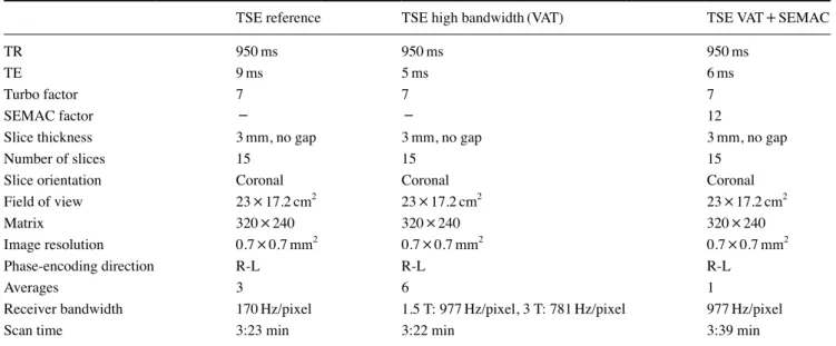
Table 2. Magnetic resonance imaging sequence parameters for the in vitro scans
TSE reference TSE high bandwidth(VAT) TSE VAT+SEMAC
TR 950ms 950ms 950ms
TE 9ms 5ms 6ms
Turbo factor 7 7 7
SEMAC factor - - 12
Slice thickness 3mm, no gap 3mm, no gap 3mm, no gap
Number of slices 15 15 15
Slice orientation Coronal Coronal Coronal
Field of view 23×17.2cm2 23×17.2cm2 23×17.2cm2
Matrix 320×240 320×240 320×240
Image resolution 0.7×0.7mm2 0.7×0.7mm2 0.7×0.7mm2
Phase-encoding direction R-L R-L R-L
Averages 3 6 1
Receiver bandwidth 170Hz/pixel 1.5 T: 977Hz/pixel, 3 T: 781Hz/pixel 977Hz/pixel
Scan time 3:23 min 3:22 min 3:39 min
of the volunteer was 180 cm, and his weight was 75 kilo-grams. The volunteer had normal facial skeletal and dental relationships. All 28 permanent teeth were erupted and no restorative, prosthodontic, or endodontic treatment had been performed. The following appliances were examined in vivo: 1) nickel-free brackets; 2) conventional stainless- steel brackets; 3) titanium brackets; 4) a banded Rapid Maxillary Expansion appliance; 5) a fixed retainer, and 6) a casted Herbst appliance. The comprehensive appliances were bonded to maxillary and mandibular acrylic aligners
(A+plastic, .040×120mm Circle 100, Dentsply, York, PA,
USA) inserted orally. The banded rapid maxillary expansion appliance was bonded just to a maxillary acrylic aligner.
The same 1.5-T and 3-T scanners, and the TSE and the TSE with high readout bandwidth for artefact suppression sequences, were used as in the vitro examinations. To eval-uate the extent of the metal-induced artefacts, images were acquired in sagittal and coronal orientations. The imaging sequences used in vitro were also used in vivo, but with slightly different parameters, as shown in Table 3.
The MR images were assessed by an experienced spe-cialist in oral and maxillofacial radiology. The following specific anatomical structures were assessed: 1) maxilla, 2) mandible, 3) nasopharynx, 4) tongue, 5) temporomandib-ular joints, 6) cranial base, and 7) eye globes. The size of the artefacts in relation to the specific anatomical structures
was evaluated using a 4-point scale, according to a
modi-fied index proposed by Zhylich et al.23 0: no artefact; 1:
minor artefact, no impact on the possibility to evaluate the anatomical structures; 2: moderate artefact, the anatomical structure is just visible; 3: major artefact, the anatomical structure is not visible. When in doubt regarding the size of the artefact in relation to the specific structure, the issue was discussed with another experienced specialist in cra-niofacial radiology until a consensus was reached.
Statistical analysis
In this study, intra-observer agreement was determined by a single re-evaluation of the first sequence for all the appliances 1 month after the first evaluation. The Cohen kappa was used to measure the level of intra-examiner
agreement.24 The intra-rater reliability was 0.62, which was
interpreted as good agreement.
Results
In vitro study
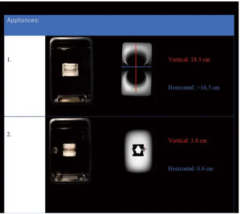
In both the 1.5-T and the 3-T scanners, only minor
arte-facts were created by the titanium brackets(1.0cm and
0.6cm, respectively) when measuring perpendicular and
parallel to the magnetic field in the images(Fig. 1). The
largest artefacts were observed for the nickel-free brackets
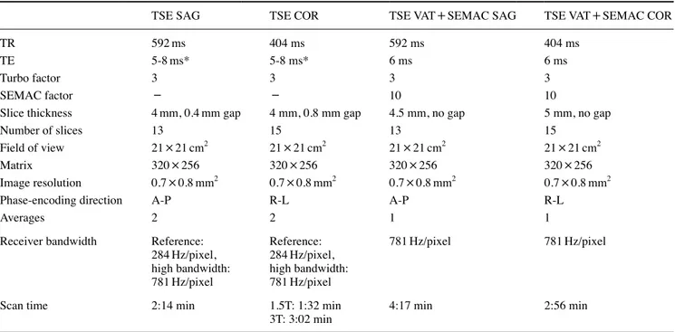
Table 3. Magnetic resonance imaging sequence parameters for the in vivo scans
TSE SAG TSE COR TSE VAT+SEMAC SAG TSE VAT+SEMAC COR
TR 592ms 404 ms 592 ms 404 ms
TE 5-8ms* 5-8 ms* 6 ms 6 ms
Turbo factor 3 3 3 3
SEMAC factor - - 10 10
Slice thickness 4mm, 0.4mm gap 4 mm, 0.8 mm gap 4.5 mm, no gap 5 mm, no gap
Number of slices 13 15 13 15
Field of view 21×21cm2 21×21cm2 21×21cm2 21×21cm2
Matrix 320×256 320×256 320×256 320×256
Image resolution 0.7×0.8mm2 0.7×0.8mm2 0.7×0.8mm2 0.7×0.8mm2
Phase-encoding direction A-P R-L A-P R-L
Averages 2 2 1 1
Receiver bandwidth Reference: 284Hz/pixel, high bandwidth: 781Hz/pixel Reference: 284Hz/pixel, high bandwidth: 781Hz/pixel 781Hz/pixel 781Hz/pixel
Scan time 2:14 min 1.5T: 1:32 min
3T: 3:02 min 4:17 min 2:56 min
TSE: turbo spin echo, SAG: sagittal orientation, COR: coronal orientation, VAT: view angle tilting, SEMAC: slice encoding for metal artefact correction, *: TE varied depending on bandwidth and between 1.5 T and 3 T, A-P: anterior-posterior, R-L: right-left
(18.5cm and >16.5cm, respectively) followed by the
stainless-steel brackets(16.0cm and 16.5cm, respectively),
the banded rapid maxillary expansion appliance(15.0cm
and 15.0cm, respectively), and the casted rapid maxillary
expansion appliance(13.5cm and 10.0cm, respectively).
Using the imaging sequences for suppression of metal arte-facts during the 1.5-T and the 3-T scans resulted in a reduc-tion of the artefacts in the images of both MR scanners.
In vivo study
Thirty MR scans, 18 using the 1.5-T scanner and 12 using the 3-T scanner, were performed. None of the appliances
created major artefacts(score 3) in the area of the TMJ or
anterior part of the cranial base when using TSE with high readout bandwidth in either scanner. Instead, it was more
common for the appliances to create major artefacts(score
3) in the structures of the pituitary gland in the images
ob-tained using the 3-T scanner(Figs. 2A and B) than in the
Fig. 1. Magnetic resonance imaging obtained using a 3-T scanner of study casts with bra c k- ets(in vitro). The large artefact is created by an Orto-Pro nickel-free bra cket(1) and the small artefact is created by a titanium bracket (2).
Fig. 2. A. Magnetic resonance image (MRI) obtained in a 3-T scanner of an object with a conventional stain-less-steel bracket(in vivo). B. MRI obtained in a 3-T scanner of an object without brackets(in vivo).
images obtained using the 1.5-T scanner(Tables 4 and 5). In the 1.5-T images, the titanium brackets caused
moder-ate artefacts(score 2) in the maxilla and mandible when only
standard TSE was used. The artefacts decreased in extent
(score 1) when TSE with VAT and SEMAC was used(Table
4).
In the images of the 3-T scanner, the titanium brackets
created major artefacts(score 3) in the structures of sella
turcica/pituitary gland when standard TSE was used and
moderate artefacts(score 2) when TSE with high readout
bandwidth was used(Table 5).
In the 1.5-T images, the conventional stainless-steel brackets and the nickel-free brackets caused major artefacts (score 3) in the structures of the maxilla when all 3 imag-ing sequences for suppression of metal artefacts were used. In addition, the nickel-free brackets also caused major
arte-facts(score 3) in the structure of the tongue(Table 4).
In the 3-T images, the conventional stainless-steel brackets
and the nickel-free brackets caused major artefacts(score 3)
in the structures of the maxilla and the mandible when stan-dard TSE and TSE with high readout bandwidth were used. The conventional stainless-steel brackets also caused major
artefacts(score 3) on the structures of the nasopharynx,
tongue, sella turcica, and the eye globe when the 2 imaging
sequences for suppression were used(Table 5).
In the 1.5-T images, the casted rapid maxillary expan-sion appliance and the fixed retainer caused major artefacts (score 3) in the structures of the maxilla when all 3 imaging sequences for artefact suppression were used. In addition, the casted rapid maxillary expansion appliance also caused
major artefacts(score 3) in the structure of the tongue. The
fixed retainer and the casted Herbst appliance caused major
artefacts(score 3) on the structures of the maxilla when
standard TSE was used. The fixed retainer caused major
artefacts(score 3) when TSE with VAT was used. When
SEMAC was added, the fixed retainer caused moderate arte-
facts(score 2)(Table 4).
In the 3-T images, the casted rapid maxillary expansion appliance and the fixed retainer caused major artefacts (score 3) in the structures of the maxilla and the mandible when standard TSE and TSE with high readout were used.
Discussion
This study showed that titanium brackets created artefacts in MR images of the anatomical structures of the head, but to a lesser degree than conventional and nickel-free brackets, the casted Herbst appliance, fixed retainers, and
the casted rapid maxillary expansion appliance. Table 4.
Assessment of artefacts in relation to appliances obtained in the 1.5
T scanner
(in vivo)
Anatomical structurers
Nickel-free brackets
Conventional stainless-steel brackets
Titanium brackets Casted rapid maxillary expander Fixed retainers Casted Herbst A B C A B C A B C A B C A B C A B C Maxilla 3 3 3 3 3 3 2 2 1 3 3 3 3 3 2 3 2 2 Mandible 3 3 3 3 3 3 2 2 1 3 3 3 2 2 2 2 1 2 Nasopharynx 2 1 1 1 1 1 1 1 0 2 1 1 0 0 0 1 0 0 Tongue 3 3 3 2 2 2 2 1 1 3 3 3 1 1 3 1 1 3 TMJ 1 1 1 2 1 1 0 0 0 1 1 1 0 0 0 0 0 0
Cranial base, clivus
2 1 1 1 1 1 2 1 1 1 1 1 0 0 0 0 0 0
Sella turcica/ pituitary gland
2 1 1 2 1 1 2 1 1 1 1 1 0 0 0 0 0 0 Eye globe 2 1 1 2 2 2 2 1 1 0 0 0 0 0 0 0 0 0
0: no artefact, 1: minor artefact, no impact on the diagnostic performance, 2: moderate artefact, the structure is just visible
, 3: major artefact, the structure is not visible,
A: turbo spin echo
(TSE) with moderate
readout bandwidth, B:
TSE with high readout bandwidth, C:
TSE with view angle tilting
(V
AT) and slice encoding for metal artefact correction
(SEMAC).
To our knowledge, this study is the first to investigate the degree of artefacts caused by commonly used orthodontic fixed appliances in images obtained using 1.5-T and 3-T scanners with different combinations of imaging sequences for suppression of metal artefacts. Currently, 1.5-T scan-ners are most commonly used. However, due to the higher image resolution and signal-to-noise ratio at 3-T, 3-T scan-ners have advantages that have contributed to their increas-ingly frequent use.
In both scanners, the titanium brackets created less exten-sive image artefacts than were caused by the conventional stainless-steel and nickel-free brackets and the casted rapid maxillary expansion appliance. This is in accordance with
previous studies on titanium brackets and artefacts.15,19,25
In-terestingly, the Herbst appliance also created less extensive artefacts in the MR images of the 1.5-T and the 3-T scan-ners than several of the other appliances. The metal com-position of the Herbst appliance is not particularly different from that of the rapid maxillary expansion appliance, con-ventional stainless-steel brackets, and nickel free brackets. Thus, the shape and position of the appliance might have been favorable for the limitation of artefacts in these
imag-es, as has been reported for other types of dental implants.26
The MR scanners used in the present study were pro-duced by Siemens. General Electrics is another vendor that manufactures scanners with other suppression sequences, such as multi-acquisition with variable resonance image
combination selective(MAVRIC SL). In a previous study
on artefacts in MR images generated by metal hip implants, the MAVRIC SL technique led to smaller artefacts than
were observed using VAT and SEMAC.27 A potential
refine-ment of this study would be to evaluate the MAVRIC-SL technique and its capacity to reduce artefacts created by or-thodontic appliances. The suppression technique was exam-ined in a previous study of patients with other types of metal
implants, and the results seem promising.28 However, it was
shown in the present study on orthodontic appliances that the different imaging sequences designed for suppression of metal artefacts had the capacity to reduce image artefacts in several craniofacial structures.
The impact of the acrylic aligners on development of arte-facts was not assessed, which might be a shortcoming of this study. However, aligners with the same dimensions were used in all the investigations, and it has been previously shown that an Essix appliance created minimal artefacts in MR images obtained using a 1.5-T or a 3-T scanner. More-over, additional investigations of acrylic aligners would have increased the burden placed on the volunteer subject.
Treatment with fixed orthodontic appliances is common,
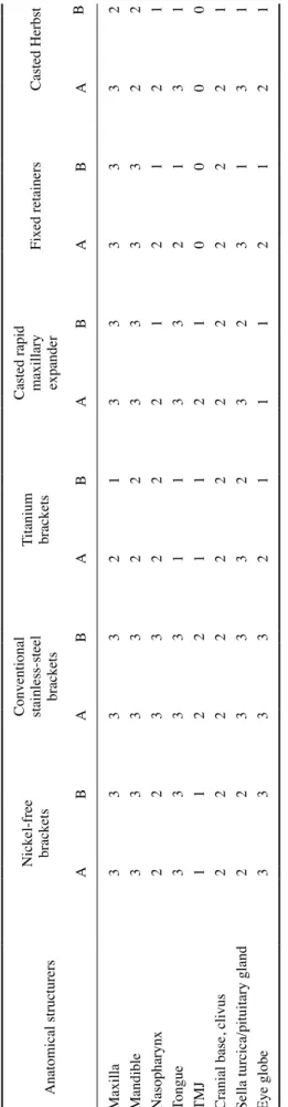
Table 5.
Assessment of artefacts in relation to appliances obtained in the 3-T
scanner
(in vivo)
Anatomical structurers
Nickel-free brackets Conventional stainless-steel brackets
Titanium brackets Casted rapid maxillary expander
Fixed retainers Casted Herbst A B A B A B A B A B A B Maxilla 3 3 3 3 2 1 3 3 3 3 3 2 Mandible 3 3 3 3 2 2 3 3 3 3 2 2 Nasopharynx 2 2 3 3 2 2 2 1 2 1 2 1 Tongue 3 3 3 3 1 1 3 3 2 1 3 1 TMJ 1 1 2 2 1 1 2 1 0 0 0 0
Cranial base, clivus
2 2 2 2 2 2 2 2 2 2 2 1
Sella turcica/pituitary gland
2 2 3 3 3 2 3 2 3 1 3 1 Eye globe 3 3 3 3 2 1 1 1 2 1 2 1 0: no artefact, 1: minor artefact, no impact on the diagnostic performance, 2: moderate artefact, the structurer is just visible, 3: major artefact, the structure is not visible, A: turbo spin echo (TSE) with moderate readout bandwidth, B:
TSE with high readout bandwidth.
and the demand for treatment will certainly increase
world-wide in the future.29 These treatments often take 18 months
or more, and after removal of the orthodontic appliance, patients commonly wear fixed retainers to maintain the treatment results for several years. Thus, clinicians will likely encounter increasingly frequent occasions when it is necessary to consider the impact of metals and the risk that artefacts on MR images may impair diagnostic accuracy.
The common guidelines that say all stainless-steel ortho-dontic appliances must be removed before MR scans using a 1.5-T or 3-T scanner, as the appliances might produce large image artefacts, can be partly rejected, since the arte-facts from the titanium brackets, the casted Herbst appli-ance, the casted rapid maxillary expansion appliappli-ance, and the fixed retainers showed relatively limited artefacts, especially in the 1.5-T scanner with TSE with VAT and SEMAC. In addition, the impact on the diagnostic perfor-mance on structures beyond the maxilla and the mandible seems to be less crucial for images performed in a 1.5-T scanner. However, it is impor tant to discuss the impact of the artefacts created by the orthodontic appliance on the MR image with the patient’s physician, since artefacts may result in under-diagnosis or difficulties in diagnosis, there-by posing a risk for delayed treatment.
All 6 orthodontic appliances in the in vivo examinations were investigated in a single healthy young adult man, which might be a limitation of this study. Nonetheless, the artefacts created by the different orthodontic appliances in the 1.5-T and 3-T scanners are easier to compare when the scanning is performed in just 1 subject. The 1.5-T and 3-T MR scanners and the orthodontic appliances examined in the present study are routinely used worldwide.
In conclusion, this study showed that fixed orthodontic appliances made of titanium, the casted Herbst appliance, and fixed retainers created less extensive image artefacts on the craniofacial structures than nickel-free and conven-tional stainless-steel brackets when standard TSE with VAT
and SEMAC was used(in the 1.5-T scanner). This study
also showed that the casted Herbst appliance and the fixed retainers caused no artefacts in 1.5-T images in the cranial structures superior to the maxilla when using TSE with high readout bandwidth. Images of appliances obtained using the 3-T scanner had, in general, a higher number of major
arte-facts(score 3) than images obtained using the 1.5-T
scan-ner. These results indicate that titanium brackets, the Herbst appliance, and fixed retainers do not need to be removed before MR scanning of the neuro-cranial structures when using a 1.5-T scanner or a 3-T scanner and applying TSE with high readout bandwidth for artefact suppression.
Conflicts of Interest: None
References
1. Cassetta M, Pranno N, Pompa V, Barchetti F, Pompa G. High resolution 3-T MR imaging in the evaluation of the trigeminal nerve course. Eur Rev Med Pharmacol Sci 2014; 18: 257-64. 2. Larheim TA. Role of magnetic resonance imaging in the clini cal
diagnosis of the temporomandibular joint. Cells Tissues Organs 2005; 180: 6-21.
3. Mazza D, Marini M, Impara L, Cassetta M, Scarpato P, Bar-chetti F, et al. Anatomic examination of the upper head of the lateral pterygoid muscle using magnetic resonance imaging and clinical data. J Craniofac Surg 2009; 20: 1508-11.
4. Fujita M, Matsuzaki H, Yanagi Y, Hara M, Katase N, Hisatomi M, et al. Diagnostic value of MRI for odontogenic tumours. Dentomaxillofac Radiol 2013; 42: 20120265.
5. Kato H, Kawaguchi M, Ando T, Aoki M, Kuze B, Matsuo M. CT and MR imaging findings of non-neoplastic cystic lesions of the parotid gland. Jpn J Radiol 2019; 37: 627-35.
6. Niraj LK, Patthi B, Singla A, Gupta R, Ali I, Dhama K, et al. MRI in dentistry - a future towards radiation free imaging - sys-tematic review. J Clin Diagn Res 2016; 10: ZE14-9.
7. Hargreaves BA, Worters PW, Pauly KB, Pauly JM, Koch KM, Gold GE. Metal-induced artifacts in MRI. AJR Am J Roentgenol 2011; 197: 547-55.
8. Beuf O, Lissac M, Crémillieux Y, Briguet A. Correlation be-tween magnetic resonance imaging disturbances and the mag-netic susceptibility of dental materials. Dent Mater 1994; 10: 265-8.
9. Fache JS, Price C, Hawbolt EB, Li DK. MR imaging artifacts produced by dental materials. AJNR Am J Neuroradiol 1987; 8: 837-40.
10. Shellock FG, Kanal E. Aneurysm clips: evaluation of MR im-aging artifacts at 1.5 T. Radiology 1998; 209: 563-6.
11. Dimberg L, Lennartsson B, Arnrup K, Bondemark L. Preva-lence and change of malocclusions from primary to early per-manent dentition: a longitudinal study. Angle Orthod 2015; 85: 728-34.
12. Thilander B, Myrberg N. The prevalence of malocclusion in Swedish schoolchildren. Scand J Dent Res 1973; 81: 12-21. 13. Starcuková J, Starcuk Z Jr, Hubálková H, Linetskiy I. Magnetic
susceptibility and electrical conductivity of metallic dental mate-rials and their impact on MR imaging artifacts. Dent Mater 2008; 24: 715-23.
14. Wylezinska M, Pinkstone M, Hay N, Scott AD, Birch MJ, Miquel ME. Impact of orthodontic appliances on the quality of craniofacial anatomical magnetic resonance imaging and real- time speech imaging. Eur J Orthod 2015; 37: 610-7.
15. Beau A, Bossard D, Gebeile-Chauty S. Magnetic resonance ima- ging artefacts and fixed orthodontic attachments. Eur J Orthod 2015; 37: 105-10.
16. Zachrisson BU, Skogan O, Höymyhr S. Enamel cracks in debonded, debanded, and orthodontically untreated teeth. Am J Orthod 1980; 77: 307-19.
17. Diedrich P. Enamel alterations from bracket bonding and debond-ing: a study with the scanning electron microscope. Am J Orthod
1981; 79: 500-22.
18. Cho ZH, Kim DJ, Kim YK. Total inhomogeneity correction in-cluding chemical shifts and susceptibility by view angle tilting. Med Phys 1988; 15: 7-11.
19. Lu W, Pauly KB, Gold GE, Pauly JM, Hargreaves BA. SEMAC: slice encoding for metal artifact correction in MRI. Magn Reson Med 2009; 62: 66-76.
20. Olsen RV, Munk PL, Lee MJ, Janzen DL, MacKay AL, Xiang QS, et al. Metal artifact reduction sequence: early clinical appli-cations. Radiographics 2000; 20: 699-712.
21. Jungmann PM, Ganter C, Schaeffeler CJ, Bauer JS, Baum T, Meier R, et al. View-angle tilting and slice-encoding metal arti-fact correction for artearti-fact reduction in MRI: experimental se-quence optimization for orthopaedic tumor endoprostheses and clinical application. PLoS One 2015; 10: e0124922.
22. Olsrud J, Lätt J, Brockstedt S, Romner B, Björkman-Burtscher IM. Magnetic resonance imaging artifacts caused by aneurysm clips and shunt valves: dependence on field strength(1.5 and 3 T) and imaging parameters. J Magn Reson Imaging 2005; 22: 433-7.
23. Zhylich D, Krishnan P, Muthusami P, Rayner T, Shroff M, Doria A, et al. Effects of orthodontic appliances on the diagnostic quality of magnetic resonance images of the head. Am J Orthod
Dentofacial Orthop 2017; 151: 484-99.
24. Landis JR, Koch GG. The measurement of observer agreement for categorical data. Biometrics 1977; 33: 159-74.
25. Elison JM, Leggitt VL, Thomson M, Oyoyo U, Wycliffe ND. Influence of common orthodontic appliances on the diagnostic quality of cranial magnetic resonance images. Am J Orthod Dentofacial Orthop 2008; 134: 563-72.
26. Shafiei F, Honda E, Takahashi H, Sasaki T. Artifacts from dental casting alloys in magnetic resonance imaging. J Dent Res 2003; 82: 602-6.
27. Kretzschmar M, Nardo L, Han MM, Heilmeier U, Sam C, Joseph GB, et al. Metal artefact suppression at 3 T MRI: comparison of MAVRIC-SL with conventional fast spin echo sequences in patients with hip joint arthroplasty. Eur Radiol 2015; 25: 2403-11.
28. Gutierrez LB, Do BH, Gold GE, Hargreaves BA, Koch KM, Worters PW, et al. MR imaging near metallic implants using MAVRIC SL: initial clinical experience at 3T. Acad Radiol 2015; 22: 370-9.
29. Livas C, Delli K. Subjective and objective perception of ortho-dontic treatment need: a systematic review. Eur J Orthod 2013; 35: 347-53.